Note: Descriptions are shown in the official language in which they were submitted.
'~ '~~ s~ '. i 3 c.~
~J V :~d ti
SLEEVE-TYPE CARRIER WITH INTEGRAL ALIGNMENT FEATURE
Field of the Invention
This invention relates to sleeve-type article carriers
having closed end panels. More particularly, it relates to
carriers of this type whose end panels have an angled portion in
order to follo~o the contours of the packaged articles.
Backaround of the Invention
Sleeve-type paperboard carriers are commonly used to
package beverage containers. They are conventionally shipped
1.C~ to bottling facilities in the form of collapsed carrier sleeves
whie:h are opened to sleeve or tubular shape so that the open
ends of the sleeves face outwardly during travel through a
packaging machine. Beverage containers are then introduced to
the sleeve through the open ends, after which the ends are
l~ closed by overlapping end flaps.
One type of carrier formed in this manner is adapted to
carry conventionally shaped bottles having relatively long
narrow necks. In order to tightly package the bottles the end
panels of the cartons are formed so that they generally conform
?D to the shape of the adjacent bottles, with the lower portion of
thrr end panels extending vertically from the bottom panel and
the upper portion of the end panels extending at an angle to the
top panel so as to follow the tapered necks of the end bottles.
To achieve this configuration the ends of the side panels of the
~ carrier are shaped according to the particular end slope
desired, Overlapping end flaps connected to the ends of the top
and bottom panels are adhered to dust flaps which are connected
along fold lines to the angled end edges of the side panels.
Although this arrangement produces a tightly bound
~ package of beverage bottles, the angled design of the end panel
is highly susceptible to misalignment of the flaps forming the
end panel. A major cause of the problem is the tendency of the
side panels to bow outwardly as the opened sleeve is pushed into
the packaging machine, apparently due to the inability of the
35 side panels to resist the vertical forces to which the sleeves
are subjected during this operation. As a result, the carrier
is not only slightly weakened, but its appearance can suffer
greatly. Usually, a package of this type contains photographs,
c; ~, : a ,~> >> s~ ~'
Lri 'J ~:i r~l
2
illustrations, legends or other indicia on the side panels. To
present a unified appearance the overlapping end panel flaps
must be precisely aligned so that the indicia on the end panels
do not appear to be broken by the composite flaps. If the side
panels are bowed at the time the flaps are adhered to the dust
flaps and to each other, the resulting carrier will be out-of-
square and the end panel indicia will exaggerate the flap
misalignment, Because this is not consistent with the quality
appearance desired of the package it is a problem that should be
1(7 resolved, Prior to this invention, however, it di d not appear
possible to correct the situation without changing the basic
sloped end panel shape or resorting to the use of thicker
paperboard stock or expensive reinforced paperboard.
It is therefore an object of the invention to provide a
1~ sleeve-type carrier of the type described which does not have a
tendency for the end panel flaps to be misaligned.
Brief Summary o.f the Invention
In accordance with the invention, an integral dust flap
is connected to the angled end edge portions of each of the side
?7 panels, and a cutout provided in the dust flap extends in toward
the fold line connecting the dust flap to the side panel. The
cutout terminates at a point which is close enough to the fold
line to permit the dust flap to be folded in about the fold line
but is spaced sufficiently to strengthen the side panel' against
?~5 a force tending to bow the side panels. Preferably, the cutout
tsrminate5 at a point relatively close to the juncture of the
angled segments of the fold line connecting the dust flap to the
end edge of the side panel. A further preferred arrangement is
far the spacing from the end of the cutout to the juncture to be
less than half the distance from the juncture to the end edge of
the dust flap opposite the fold line. If desired, the portion
of the dust flap between the juncture of the angled segments of
the fold line and the cutout may contain a score line or a cut
to facilitate folding of the dust flaps.
3~ Because this arrangement strengthens the carrier sleeve
to the point that it resists bowing when introduced into the
packaging machine, the resulting straight side panels allow the
dust flaps and the overlapping end flaps to be properly aligned.
.,
~,~ ~~J.:i~7
3
The above and other aspects of the invention, as well as
other benefits, will readily be ascertained from the more
detailed description of the preferred embodiment of the
invention which follows.
Brief Description of the Drawings
FIG, i is a pictorial view of a sleeve-type carrier
incorporating the present invention;
FIG. 2 is a partial pictorial view of a prior art
carrier sleeve, shotaing an open end thereof;
1(7 FIG. 3 is an end view of a prior art carrier formed from
the sleeve of FIG. 2;
FIG. 9 is a plan view of a blank used to form the
c:arxier of the present invention;
FIG. 5 is a partial pictorial view of the carrier sleeve
of the present invention, showing an open end thereof;
FIG. 6 is a partial side view of the carrier sleeve of
the invention, showing the dust flap in open condition prior to
being folded in during the forming of the end panel;
FIG. 7 is an end view of the carrier sleeve of FIG. 6,
showing the dust flaps in folded condition;
FIG. $ is an end view of a carrier formed from the
sleeve of FIG. 7;
FIG. 9 is a view similar to that of FIG. 6, but showing
a modified dust flap; and '
FIG. 10 is a view similar to that of FIG. 6, but showing
another modified dust flap.
Description of the Preferred Embodiments
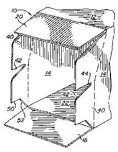
Referring to FIG. 1, a carrier 10 embodying the features
of the invention comprises a top panel 12, a bottom panel not
visible in this view, side panels 14 connecting the top and
bottom panels and end panels 16 connecting the top, side and
bottom panels. Each side panel is made up of a lower vertical
portion 18, which is substantially perpendicular to the bottom
panel, and an upper angled portion 20 which extends from the
lower vertical portion 18 to the top panel 12. The lower
portion of each side panel is longer than the upper side panel
portion in order to correspond to the contout of the end panels
to which the side panels are connected. The top panel 12, which
4 ~~) J~;):~
connects the short upper edge of the side panels, is
correspondingly shorter than the bottom panel, which connects
the longer lower edge of the side panels.
In order to better understand the problem facing prior
art carriers of similar shape, a typical prior art sleeve 100
adapted to be formed into a carrier of substantially the same
shape as the carrier of FIG. 1 is shown in FIG. 2. The prior
art sleeve comprises a lower dust flap 102 foldably connected to
the lower vertical edge of each of the side panels 114 and an
1(7 upper dust flap 104 foldably connected to the upper angled edge
of the side panels 114. II1 forming a carrier from the sleeve,
tha dust flaps 102 and 104 are folded in after the sleeve has
teen loaded with beverage bottles and the upper and lower end
flaps 10~ and 108, which are connected to the top and bottom
1~ panels 112 and 116, are folded and glued to the folded-in dust
flaps, Typically, the upper end flap 106 is longer than the
lower end flap 108 and will be folded down first. It is then
glued to the upper dust flaps 104 and to the upper portion of
the lower dust flaps 102 prior to the lower end flap 108 being
20 folded up, The lower end flap 108 overlaps the end flap 106 and
is glued to both the lower dust flaps 102 and to the overlapped
portion of the upper end flap 106.
The areas 110 at the edge of the side panels 114 between
the dust flaps 102 and 104 tend to buckle when a vertical force
2~ is applied to the carrier of the magnitude routinely applied in
the course of the carrier sleeve being introduced to a packaging
machine. Similarly, the side panels tend to be bent or bowed
autwardly adjacent the intersection of the bottom panel 116 and
the lower end flap 108 when a vertical force of the same
3t~ magnitude is applied to the carrier. It can be seen that this
area of the side panel is unsupported due to the spacing of the
lower dust flaps 102 from the bottom panel 116 in order to be
able to clear certain elements of the packaging machine during
travel of the carrier sleeve through the packaging machine.
3~ When the side panels become distorted due to the buckling and
bowing action described, the subsequent folding and gluing of
the dust flaps and the end flaps after bottles have been loaded
into the carrier often results in the package being permanently
' CA 02026935 2001-06-19
misaligned, as illustrated in FIG. 3 and as graphically
indicated by the lateral dimension arrows 105. It can be
seen from FIG. 3 that the side panels 114 have been fixed
in their bowed position, with portions of the dust flaps
5 102 and 104 being visible. This causes the end flaps 106
and 108 to be misaligned so that any indicia on these flaps
intended to be part of an overall composite indicia
covering the entire end panel will be misaligned as well,
destroying the intended visual impact.
The problems of the prior art carriers are solved by
the present invention which is shown in blank form in FIG.
4. The blank 10A is comprised of a bottom panel section 22
connected along its side edges by fold lines 24 to the side
panel sections 14. A top panel section 12A is connected
along its interior edge by fold line 26 to the adjacent
side panel 14. Another top panel se<:tion 12B is connected
along its interior edge by fold linE~ 28 to the other side
panel section 14. The top panel section 12A is adapted to
overlie and be adhered to the top panel section 12B. Handle
openings may be provided in the top panel of the carrier
formed from the blank by aligned openings in the top panel
sections, indicated by the tabs 30 which cover the openings
in the section 12A and the tabs 32 which cover the openings
in the section 12B. The underlying top panel section 12B
may also be provided with a hinged dz:op-down divider panel
34 to separate bottles in the carrier. Since neither the
handle nor the divider panel affects the functioning of the
present invention, the provision of such a divider panel
is optional and the particular design of the handle is a
matter of choice unrelated to the invention.
It can be seen from FIGS. 1 and 4 that the fold lines
24 are longer than the fold lines 26 and 28, causing the
top panel formed by the sections 12A and 12B to be shorter
than the bottom panel 22. This is necessary due to the
' CA 02026935 2001-06-19
6
inwardly directed angled portion of the end panels of the
carrier. The shape of the end panels is delineated by the
edges of the side panels, whereby the lower portion of the
end panels of a carrier formed from the blank is defined by
the side panel edges 36 extending at right angles from the
fold lines 24, and the upper sloped portion of the end
panels is defined by the angled side panel edges 38
connecting the edges 36 to the fold lines 26 and 28.
A dust flap 40 is connected to each end edge of the
side panel sections 14 along a fold line corresponding to
the side panel edges 36 and 38. Each dust flap contains a
cutout 42 which terminates in a radius or arcuate portion
44 spaced from and in the vicinity of the juncture between
the fold line segments corresponding to the edges 36 and
38. End flaps 18 are connected to the end edges of the
bottom panel section 22 along fold .Lines 46 and end flaps
are connected to the end edges of the top panel section
12A along fold lines 48. The portion of the dust flaps 40
connected to the fold line 38 extends to the intersection
20 of the fold lines 38 and 26, providing support for the side
panel edges up to the top panel. The portion of the dust
flaps connected to the fold line 36 extends to the
intersection of the fold lines 36 and 24, providing support
for the side panels down to the bottom panel 22. Thus there
is an unbroken connection between each dust flap and its
associated side panel.
Although the dust flaps 40 extend all the way to the
fold line 24 connecting the side panels to the bottom
panel, it will be noted that the be>ttom edges 50 of the
dust flaps are spaced from the end :Flaps 18 to allow for
the carrier sleeve to pass through the packaging machine
without being interfered with by any ~of the elements of the
machine. The spaced edge 50 is connected to the
intersection of the fold lines 36 and 24 by diagonal edge
CA 02026935 2001-06-19
6a
52 which permits the edge 50 to be spaced from, while at
the same time providing for side panel support at, the
bottom of the side panel.
To form a collapsed carrier sleeve from the blank 10A
of FIG. 4 the top panel section 12E3 is folded about fold
line 28 so as to be in face-to-face relationship with the
adjacent side panel 14. The other side panel 14 is then
folded up about its fold line 24, causing the top panel
section 12A to directly overlie 'the folded top panel
section 12B. By gluing the top panel sections to each other
in areas that adhere the two sections together without
bonding the top panel section 12A to
'~~?f3~;~3
the divider panel 34, the divider panel will be free to pivot
down into place upon opening the collapsed sleeve.
In the packaging machine the collapsed sleeve is opened
into the tubular shape of FIG. 5, with the dust flaps 40 and the
end flaps 18 and 20 extending out from the side, top and bottom
panels. The full support provided the side walls 14 by the
connected dust flaps 40 is further illustrated in FIG. 6, which
shows the upper portion of the dust flap connected to the fold
line segment 38 up to the top panel 12 and the lower portion of
1C7 the dust flap connected to the fold line segment 36 down to the
battom panel 22. It is in this condition, prior to being loaded
with bottles, that the carrier sleeve is most vulnerable to
vertical forces causing the bowing or buckling of the side
panels 14. As stated above, the critical area at the bottom of
I3 the Side panels is strengthened by the connection of the dust
flaps to the side panels down to the bottom panel. The critical
area between the vertically spaced dust flaps of the prior art
is eliminated by making the upper and lower segments of the dust
flap 90 integral and by connecting the integral dust flap 40 to
?0 both of the fold line segments 36 and 38 even though the fold
line segments extend in different directions. By eliminating
the gap in the prior art arrangement at the juncture of the fold
lines 36 and 38, the side panels are strengthened in this area
and as a result they resist buckling when exposed to the normal
2~ vertical stresses in the packaging machine. The best location
zaf the end 44 of the cutout 42 may vary according to the
specific design of the carrier, but it should be far enough from
the dust flap fold line to allow significant strengthening of
the side panels but not so far that the width of the dust flap
~t~ at that point interferes with the inward folding of the dust
flaps. As an example, it has been found that a spacing of 1/2
inch adequately strengthens the side panels without interfering
with the folding of the dust flaps.
After the sleeve has been loaded, the dust flaps are
35 then folded in about their fold lines 36 and 38. The sleeve
appears from an end view as shown in FIG. 7, which shows the end
bottles B of a carrier designed to hold three rows of four
bottles each. The side panels are straight and have not been
s s»;jF,~
~~~..-..)..,~~3
distorted. The same view after the end flaps 18 and 20 are
folded into place and glued is shown in FIG. 8, wherein the
fully packaged and closed carrier is illustrated as being
effectively squared-up, with the end panels being in proper
alignment. In this condition, any indicia on one end panel flap
intended to be a continuation of indicia on the other end panel
flap is properly aligned, and the adhered end flaps give the
appearance of a single end panel.
Referring to FIG. 9, wherein like reference numerals to
those discussed in connection with FIGS. 1 and 4 to 8 refer to
like elements, the dust flap 40 has been provided with a score
line 50 extending from the intersection of the fold lines 36 and
38 to the end 44 of the cutout 42. This is for the purpose of
facilitating the folding action of the dust flaps in order to
overcome any tendency for the dust flaps to wrinkle or fold in
this area. This may be especially useful if it is desired to
maximize the width of the dust flap between the fold line
intersection and the cutout to obtain greater resistance to
bowing and buckling without creating. problems in the dust flap
?0 itself due to the greater width. Similarly, 'the arrangement of
FIG, 10, wherein a cut or slit 70 is provided between the fold
line intersection and the end of the cutout instead of a score
line, may be used for the same purpose.
It will now be understood that the invention enables a
'?5 carrier of the same shape and size as 'those of the prior art to
tae utilized without the danger of end panel misalignment and the
accompanying problems detailed above. The invention involves
only sligh'c changes from the point of view of carrier blank
production and does not require extra blank material. As a
~C~ result the invention does not increase the expense o.f the
carrier.
It should now be apparent that although the invention
has been described in connection with the preferred embodiments,
it is contemplated that those skilled in the art may make
35 changes to certain features of the preferred embodiments without
altering the overall basic function and concept of the invention
and without departing from the spirit and scope of the
invention, as defined in the appended claims.