Note: Descriptions are shown in the official language in which they were submitted.
PROCESS AND APPARATUS FOR TREATING ION EXCHANGE RESIN
FIELD OF THE INVENTION
This invention relates to a process and apparatus for
treating ion exchange resin. More particularly the
process and apparatus are directed at removing
interspersed insoluble particulate matter from the
resin.
BACKGROUND OF THE INVENTION
The use of ion exchange resins, usually in the form of
spherical beads, for selective removal of dissolved
mineral constituents from water is generally well
known. These dissolved constituents may either be
positively charged ions (so-called rations) or
negatively charged ions (so-called anions).
The presence of certain ions in domestic and
industrial waters is known to be particularly
undesirable. Thus the rations of calcium (Ca2+) and
magnesium (Mg2+) contribute to so-called "hardness" of
water, while dissolved anions such as sulphate (SOq,2-)
can contribute to corrosion and scaling problems in
industrial applications. The occurrence of the
abovementioned ions is common in waters associated
with mining operations, making disposal of such water
problematic.
Ion exchange resins generally selectively adsorb
rations or anions onto the surface of the resin beads
and are accordingly catergorised as cationic or
anionic resins. During use the resins become
progressively loaded with ions being removed from the
GEN\G0454
~~s~vz~~
water passing the resin beads. ~eriudic regeneration
accordingly becomes necessary in order to strip these
ions from the resin in order to make it fit for use
again.
Resin regeneration generally involves taking the resin
out of service and bringing it into contact with an
aqueous liquor containing at least one reagent capable
of removing the adsorbed ions from the resin.
Sulphuric acid (H2S04) is a known suitable reagent far
regenerating cationic resins, while lime (Ca(OH)2) is
known for its use in regenerating anionic resins. The
advantage of these reagents in relation to other known
reagents lies in their comparatively low cost, which
makes them suitable for use in large-scale water
treatment installations.
Regeneration is generally effected by bringing a resin
into contact with a regenerating liquor. This may be
an aqueos solution of sulphuric acid or lime,
depending on the type of resin being treated. Tn the
case of a regenerating liquor comprising lime, this
may only be partially dissolved, the balance being
dispersed in water as finely as dispersed particles.
Whereas sulphuric acid is used in regenerating liquors
in a fully dissolved state, regenerating liquors
comprising lime generally contain a fraction of
undissolved lime particles which remain dispersed
within the liquor throughout the regeneration process.
The use of the abovementioned reagents becomes
problematic, however, whenever any of the ions
adsorbed onto the resin insoluble products in
C3EN\Q0454
~~1~'l~'~5
conjunction with the regenerating reagent. The
regeneration of a cationic resin loaded with calcium
ions, by means of a regenerating liquor comprising
sulphuric acid is a typical example. This can be
illustrated by means of the following mechanism
R-Ca + H2S04 (aq) -°-~~ R-H2 + CaSOq, where
R-Ca represents the cationic resin loaded with calcium
ions;
H2S04(aq) represents an aqueous solution of sulphuric
acid, as used in the regenerating liquor:
R-H2 represents the regenerated resin: and
CaS04 represents gypsum, which is poorly soluble in
water.
The gypsum tends to precipitate from solution in the
form of minute hydrated mineral particles, generally
described by the chemical formula CaS04.xH20. These
particles precipitate on the surface of the resin
being regenerated, rendering the resin at least
partially ineffective for further cation removal.
Anionic resin which is regenerated with an aqeous lime
solution can suffer similar deterioration when it is
loaded with anions such as sulphate (5042). This is
illustrated by the following mechanism:
R~S04+Ca(OH)2(aq) -~----~ R'-(OH)2+ CaS04, where
R°-S04 represents the anionic resin loaded with
sulphate ions ;
Ca(OH)2(aq) represents an aqeuos solution of lime, as
used in a regenerating liquor;
GEN\G0454
2(1~'~~"75
R-(OH)2 represents the regenerated resin; and
CaS04 again represents gypsum.
The precipitation of gypsum and other insoluble
products formed by similar mechanisms tends to lead to
long-term resin deterioration by successive
regeneration steps. This problem can be counteracted
by the provision of small particles of insoluble
regeneration product (so-called seeding particles)
interspersed with the resin at the commencement of
each regeneration step. It has been found that as
further regeneration products such as gypsum are
formed, these tend to precipitate preferentially on
the seeding particles, leaving the resin substantially
uncontaminated at the end of each regeneration step.
It is an object of the present invention to provide a
process and apparatus which are particularly suited
for the treatment of ion exchange resin having
insoluble particulate matter such as the seeding
particles, or undissolved lime particles, interspersed
with it.
SUMMARY OF THE INVENTION
According to the present invention there is provided a
process for treating ion exchange resin, which
includes the steps of
-introducing a liquor for treating the resin in
substantially vertical upflow into a treatment zone in
order to produce a fluidised bed comprising the resin
and insoluble particulate matter interspersed with the
each other; and
-separating the resin from the particulate matter
GEN\G0454
5
through entrainment of the latter by the liquor from
being withdrawn from the fluidised bed in a
substantially horizontal flow direction.
In this process the particulate matter, eg. seeding
particles, may be introduced into the treatment zone
together with the liquor. Separation of the
particulate matter from the resin is preferably
effected in a zone extending vertically into the
fluidised bed.
The process described above may be followed by a
further step during which at least a portion of the
separated particulate matter is recovered for
re-introduction into the treatment zone.
In a further aspect of the invention there is a
provided an apparatus for treating ion exchange resin,
which includes
-a vessel defining a resin treatment zone into which
the resin is receivable;
-a liquor inlet arranged below the resin treatment
zone fox introducing liquor for treating the resin in
substantially ,vertical upflow in order to allow a
fluidised bed of resin to be produced in the treatment
zone; and
- separating means extending into the treatment zone
whereby , in use, insoluble particulate matter
interspersed with the resin is allowed to be entrained
from the treatment zone by the liquor flowing in a
substantially horizontal flow direction while the
resin is retained in this zone.
The apparatus described above may further include
DEN\G0454
6 c~
guide means for directing the liquor from the liquor
inlet in substantially vertical upflow towards the
treatment zone.
The separating means may include a screen having
sufficiently small apertures for retaining the resin
in the treatment zone. The separating means may be
cylindrical in shape and be arranged vertically within
the vessel.
DESCRIPTION OF DRAWINGS
The invention is described below by way of example
with reference to the accompanying drawings, in which
FIGURE 1 shows in diagrammatic form a
vertical section along the central axis of an
apparatus according to the invention;
FIGURE 2 shows a schematic flow diagram of a
regeneration process according to the invention,
using the apparatus of Figure 1; and
FIGURE 3 shows a schematic flow diagram of a
rinsing process according to the invention, using the
apparatus of Figure 1.
SPECIFIC DESCRIPTION OF AN EMBODIMENT OF THE
INVENTION AND EXAMPLES OF ITS USE
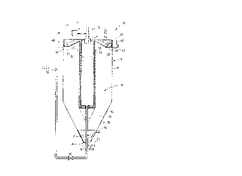
In the drawings reference numeral 10 denotes
generally an apparatus according to the invention.
More particularly the apparatus l0 described below
relates to a pilot-scale installation operated by the
applicant.
GEN\G0454
~~~ ~~~~J
The apparatus 10 includes a vessel 12 of circular
cross-section having a base 14 of inverted conical
shape cannected below a cylindrical portion 16. In
the applicant's pilot-scale unit the cylindrical
portion 16 has a diameter of approximately 400mm and
a height of approximately 650mm. The conical base 14
has a slope angle of 60°, giving the vessel 12 an
overall height of approximately 1 metre.
The conical base 14 and cylindrical portion 16
together define the outer periphery of a resin
treatment zone 18 into which resin is receivable via
a resin inlet pipe 20 discharging into the vessel 12.
A liquor inlet 22 is connected towards the bottom of
the conical base 14 in order to allow liquor for
treating the resin to discharge into the lowermost
portion of the conical base. A deflection plate 24
adjacent to the liquor inlet 22 is so arranged within
the conical base 14 as to direct liquor issuing from
the inlet 22 in an approximately vertically upward
direction. Guiding vanes 25 arranged at 90° in
relation to each other are fitted within the vessel
12 in order to ensure an evenly distributed upward
flow of liquor.
The conical base 14 has proven to be satisfactory for
the purposes of the pilot-scale installation referred
to above. It is believed, however, that
flat-bottomed vessels having flow distributor nozzles
and/or pipes suitably arranged above their floors can
be used to similar effect, particularly in
large-scale installations.
GEN\G0454
The apparatus 10 is provided with separating means in
the form of an internal screen 26 of circular
cross-section which is held in position by a vertical
support 28 connected to a cover (not shown) resting
on top of the vessel 12. The screen 26 is
constructed of wire of trapezoidal cross section
(so-called wedge-wire) wound onto a cylindrical
former (not shown) in order to provide apertures
approximately 0,25 mm wide between adjacent runs of
wire. In the applicant's pilot-scale apparatus the
internal screen 26 has a diameter of approximately
170mm and a height of approximately 700mm. The
screen 26 is located in co-axial arrangement with
reference to the cylindrical portion 16 of the vessel
12. The treatment zone 18 accordingly comprises an
annular region extending upwardly from the conical
base 14.
The annular configuration of the treatment zone 18
has been found satisfactory for the purposes of the
pilot-scale installation referred to above. It is
believed, however, that a plurality of screens 26
arranged in a comparatively large vessel in similar
orientation and spaced from each other would be
equally suitable in large-scale installations. The
general consideration to be observed in both the
pilot-scale and the large-scale installations is that
the path-length between particles interspersed with
the resin in the treatment zone 18 and the separating
means is kept as short as possible.
The screen 26 is sealed at its upper and lower ends
and has a screen outlet pipe 30 connected to its
GEN\G0454
9 ~U2'~~'~~
lower end providing a liquor flow path from the
screen via the lowermost level of the conical base 14
and via a control valve 32 towards a siphon-break 34.
A conical unit 35 is connected to the outlet pipe 30
immediately below the screen 26 in order to provide a
relatively smooth flow transition of liquor from the
inlet 22 towards the annular portion of the treatment
zone 18. The provision of the unit 35 has been found
to reduce the degree of flow turbulence before liquor
enters the treatment zone 18 during use of the
apparatus 10.
An overflow weir 36 is arranged circumferentially
along the upper. portion of the cylindrical portion 16
of the vessel 12. A weir overflow screen 38 arranged
immediately above the overflow weir 36 serves as a
further separating means constructed of the same type
of wedge-wire spaced apart in similar fashion as with
the internal screen 26. A weir overflow launder 40
arranged adjacent to the overflow weir 36 directs
liquor passing through the screen 38 towards an
overflow outlet 42.
The apparatus 1o includes cleaning means having a
rotatable wiper assembly 44 driven by an electrically
powered motor 46. The assembly 44 is pivotally
connected to the vertical support 28 of the internal
screen 26 by way of a bush 48. The assembly 44 is
fitted with wiper blades 50 and 52 which are swept
past the internal screen 26 and the weir overflow
screen 38 respectively at a rotational speed ranging
from 30 to 60 revolutions per minute, in order to
dislodge particles likely to foul the screen
apertures.
GeN~coasn
10
~~~ t~~~J
In an illustrative process using the apparatus 10, a
batch of loaded cationic resin beads is removed from
the feed-end of a train of interconnected ion
exchange vessels in which raw mine water is
demineralised. The resin is loaded for regeneration
into the vessel 12 via the resin inlet 20. In the
applicant's pilot-scale unit referred to above 50
litres of resin beads constitute a suitable batch
size. The cross sectional diameter of the individual
resin beads is of the order of 0,5 to 1,2 mm.
A portion of the water distributed among the beads of
resin in the vessel 12 is drained from it and
replaced with slightly acidic rinse water, which is
retained from a preceding resin regeneration cycle.
Regenerating liquor for treating the resin in the
vessel 12 is drawn from a stirred tank (not shown) in
which seeding particles of gypsum having diameters up
to 0,01 mm are kept in suspension.
In Figure 2 flow arrow 54 schematically illustrates
how the regenerating liquor is introduced into the
vessel 12 via the liquor inlet 22. The liquor is
diverted upwardly along a vertical flowpath by the
deflection plate 24 and the guiding vanes 25, as
indicated by the flow arrows 56. The liquor flow
rate is sufficiently high to transport the bulk of
the resin into the annular region of the resin
treatment zone 18 adjacent to the screen 26.
Under the described conditions the regenerating
liquor and seeding particles pass freely around
herein beads being kept suspended within the liquor
OEN\00454
11
and spaced apart from each other in what is termed a
"fluidised bed" condition. The overall volume of the
resin in the fluidised condition is preferably
between 150 and 200 of the volume of the resin in
its unfluidised state. The hatching shown in Figure
2 indicates the approximate location of the fluidised
resin in the vessel 12.
While the control valve 32 remains shut the
regenerating liquor and at least the seeding
particles of relatively small cross-section leave the
resin treatment zone 18 via the overflow weir 36,
after separation from the resin beads by the weir
screen 38, as illustrated by the flow arrows 58 in
Figure 2. The regenerating liquor and seeding
particles pass along via the weir overflow launder 40
to the overflow outlet 42 as indicated by the flow
arrow 60.
At the commencement of the regeneration process the
regenerating liquor and entrained seeding particles,
denoted by flow arrow 60 are initially recirculated
via the stirred tank referred to above, back to the
apparatus 10 via the liquor inlet 22 for a period of
approximately 10 minutes. Sulphuric acid is then
dosed into this stirred tank, where the heat of
dilution generated by the addition of the acid is
allowed to dissipate before the regenerating liquor
is fed to the vessel 12 as indicated by the flow
arrow 54. The acid dosing rate is controlled so as to
maintain a pH of about 1,5 (or a conductivity of
approximately 20 000 microsiemens/centimetre) on the
launder outlet flow 60 while maintaining liquor
recirculation as described above for a period of
GEN\G0454
12
approximately 20 minutes. Recirculation is
maintained for a further time interval of
approximately 10 minutes after acid dosing has ceased.
It is generally desirable to maintain intimate
contact between the regenerating liquor and the resin
in its fluidised state throughout the regeneration
step described above. It is believed that this
objective can be met in practice by adapting the
configuration of the vessel 12 and the separating
means 26 shown schematically in the drawings
according to the type of resin being treated and the
flow conditions that are required in the resin
treatment zone 18.
It has been found , for example, that the cross
sectional area of the annular region of the treatment
zone 18 should be somewhat smaller for the cationic
resin used in the applicant's pilot-scale
installation than for anionic resin treatment when
using similar liquor flow rates. This is mainly
attributable to the relatively higher density and
greater bead diameter diameter of the cationic resin
used in relation to the corresponding anionic resin.
A relatively higher upward liquor flow velocity is
accordingly required for the treatment of the
cationic resin in order to achieve satisfactory
fluidisation.
The flow pattern of liquor through the treatment zone
18 may be optionally varied in the vertical
direction. More parta~cularly the treatment zone 18
may be constituted by a lower liquor distribution
region immediately below the annular region described
GEN\G0454
13
above. This region is defined by the conical base 14
in the drawings, and allows a substantially uniform
distribution of liquor into the higher-lying region
for resin fluidisation.
The last-mentioned region may be constricted towards
its lower end (not shown in the drawings) in order to
create a relatively high degree of turbulence in the
lowermost portion of the fluidised resin bed. This
turbulence promotes rapid mixing of the resin and the
regenerating liquor entering the fluidised bed.
As the cross-sectional area of the treatment zone
increases in the upward direction the upward velocity
of the regenerating liquor is allowed to decrease and
fluidisation becomes less vigorous. The upper region
of the fluidised resin bed is usually discernible as
a visible resin/liquor interface, which preferably
lies below the upper edge of the overflow weir 36.
The portion of the treatment zone 18 immediately
above the resin/liquor interface serves as a
separation zone in which relatively large particles
of insoluble matter are allowed to return to the
fluidised bed while the smaller particles are
entrained by the liquor towards the overflow weir 36.
The region immediately adjacent to the weir 36 is
termed a stilling zone, where the flow velocity of
liquor is at its lowest in order to allow a
substantially uniform flow of liquor across the weir.
It will be appreciated that the concentration of
gypsum in the regenerating liquor is virtually at
saturation level at the commencement of the
GEN\G0454
14
regeneration step described above. The formation of
further gypsum by the mechanism illustrated above
will accordingly commence almost immediately when the
acidic regenerating liquor reaches the fluidised
resin, leading to a growth in the seeding particles
within the resin treatment zone 18.
At the end of the resin regeneration step described
above the control valve 32 is opened and the flow
of regenerating liquor across the overflow launder 38
is diverted through the screen 26 in a horizontal
flow direction as illustrated by the flow arrows 62
in figure 3. Acid dosing to the stirred tank is
simultaneously terminated. The liquor and entrained
insoluble particles in the treatment zone 18 pass
through the apertures of the screen 26 in a
substantially horizontal flow direction, leaving
behind fluidised resin in the treatment zone 18.
The liquor subsequently flows through the outlet pipe
30, the valve 32 and into the siphon-break 34, which
is so positioned that the screen 26 remains
continuously immersed in upwardly flowing liquor in
the vessel 12. The liquor leaving the siphon break
34 is fed to a settler (not shown) in which the
entrained particles are collected in an underflow
stream for final disposal. The clarified settler
overflow is returned to the vessel 12 along the flow
path shown by the arrow 54. A progressive removal of
particulars from the fluidised bed in the treatment
zone 18 is accordingly effected. This is
substantially complete after a time interval of
approximately 30 minutes.
GEN\G0454
15
The flow of clarified liquor to the vessel 12 is
subsequently terminated and the resin settles into
the conical base 14. The remnant liquor in the
vessel 12 is drained from the vessel 12 and a stream
of rinsing liquor is introduced into the vessel 12
via the liquor inlet 22 as illustrated by flow arrow
54. The rinsing liquor is directed into the resin
treatment zone 18 and withdrawn from it in similar
fashion as the regenerating liquor during the resin
regeneration process.
It appears from the applicant's pilot-scale trials
that gypsum particles of comparatively large sizes
will accumulate towards the lower region of the resin
treatment zone 18 in the course of the regeneration
step. Smaller particles, by comparison, tend to be
more readily entrained upwardly by the upflowing
liquor. The configuration of the apparatus 10 allows
gypsum particles of a variety of different shapes and
sizes to be removed from the resin treatment zone 18.
This is mainly achieved by the arrangement of the
internal screen 26, which extends virtually through
the entire depth of the region of the treatment zone
18 occupied by the fluidised resin bed. The
apertures of the screen 26 may optionally extend to
above the fluidised bed for removal of very fine
particles from the treatment zone 18 .
The apparatus described above allows a variety of
adaptations in its construction and the flow
configuration, all falling within the scope of the
present invention. This invention should accordingly
not be construed as being limited in scope to the
embodiment and process described above.