Note: Descriptions are shown in the official language in which they were submitted.
Process and Apparatus ~or Decantation of Suspensions
Background of the Invention
This invention relates generally to the decantation of
suspension, and more particularly to a process and
apparatus for decanting at temperatures at and above the
atmospheric boiling point of the liquid.
Decantation systems of the general type described
herein are already known and are often referred to as
continuous thickeners. The purpose of such systems is to
obtain sedimentation, i.e. gravitational settling oE solid
particles suspended in a liquid. The settled solid
particles are withdrawn at the bottom of the apparatus and
the clarified liquid, freed from the solid particles, is
withdrawn from the top of the apparatus.
Somora et al U.S. Patent 3,628,667 described a
decantation apparatus in the form of a horizontally
elongated vessel (Col. 1, lines 66 to 68), of height
approximately equal to width, in which a slurry inlet is
positioned below the surface of the liquid inside the
vessel. The discharge of clarified liquors is by launders
located at the surface of the liquid, and a slurry feed
enters the apparatus at effectively atmospheric pressure,
since it is dispensed from a feed well open to the
atmosphere. The basic concept resides in the fact that
the suspension to be clarified is distributed in a
distribution chamber and loading well evenly over the
entire length of the decantation vessel (Col. 2, lines 62
to 64) which is realized by a distributor chamber
extending lengthwise of the vessel substantially
coextensive therewith in the top section (Col. 1, lines 74
to Col. 2, line 2).
In Casey, U.S. Patent 4,603,000, there is described an
apparatus and process for flocculating and clarifying a
solid-liquid slurry in a vertically oriented apparatus
whose height is approximately equal to its dia~eter. An
inlet for the deaerated and flocculated slurry is provided
. ,.
, .
-.~ .
-2-
below the surface of the liquid inside the vessel and
below the surface of the mud bed (Col. 2, line 48).
Furthermore, the ap~aratus includes a preflocculating
vessel extending into the top, and arranged coaxially with
the clarifier tank (Col. 2 to Col 13 line 21).
A flocculating agent is added to the slurry as it passes
downwardly under laminar flow through a vertical pipe
arranged coaxially with the clarifier vessel. The
direction of flow then is changed to become upwardly
through a lcwer chamber for the formation of the flocs,
and then its direction is changed again to flow downwardly
through an annular passage surrounding the lower chamber
and finally is introduced below the surface of the mud bed
tCol. 3, lines 8 to 21). This apparatus includes a
conical bottom section fitted with a slowly rotating rake
that grazes the inner surfaces of the lower portion of the
vessel. The discharge of clarified liquor is by launders
located at the surface of the liquid, and the feed slurry
is effectively at atmospheric pressure, since it is
dispensed from a feed well open to the atmosphere.
Spetz, German OS 2 212 646, published August 3, 1972,
describes a vertically oriented cylindrical decanter of
height smaller than the diameter, having inlets Eor the
feed slurry located below the surface of the liquid, just
above the upper surface of the mud bed. The exit oE
clarified liquor is by launders located àt the surface of
the liquid and the entry of the feed slurry is effectively
at atmospheric pressure, since it is dispensed from a feed
~ell open to the atmosphere.
In alumina plants, associated with the production of
aluminum, there is a need for an improved system for
separating finely divided red mud solids from digestion
liquors. It is the object of the present invention to
provide a means whereby finely divided solids can be
rapidly separated from a slurry at temperatures above the
boiling point of the liquid.
-3- ~ ~s~
Summary of the Invention
One embodiment of this invention relates to a
decantation apparatus which comprises a vertically
elongated vessel having a cylindrical upper section and
a bottom section and arranged to be filled to a
predetermined liquid level in an upper region of the
cylindrical upper section. Feed means are provided for
feeding a suspension into the cylindrical section in a
mid-region between the bottom of tbe vessel and the liquid
level. Means are also provided for adding a flocculant to
the suspension feed. A liquid outlet means is provided in
an upper region of the cylindrical section below the
liquid level for drawing off clarified liquid. A solids
discharge is provided at the bottom of the vessel and
means are also provided for controlling a solids component-
liquid component interface at a predetermined level in a
lower region of the cylindrical portion below the inlet.
A rotatable rake means is provided in the bottom section
and is adapted to remold the sedimented solids.
The apparatus is preferably tall relative to its
diameter and typically has a height:diameter ratio of
about 3 to 2:1. The liquld outlet may be at the
predetermined liquid level or a distance below the liquid
level, e.g~ about 0.5-1.0 H, preferably 0.7-1.0 H, from
the bottom of the vessel, where H is the height between
the bottom of the bottom section and the liquid level.
Of course, the outlet must always be above the inlet.
The bottom section may have a variety of shapes, e.g.
dished or flat.
Another embodiment of this invention comprises a
process for flocculating and clarifying a solid-liquid
suspension comprising the steps of providing an elongated
vessel having a cylindrical upper section and a dished or
flat bottom section and maintaining a liquid level in the
vessel in an upper region of the cylindrical upper section.
A suspension is fed into the cylindrical section in a
1: .
,
': ': : ' :
,:
~4~ ~ ~2 ~t~
~id-region between the bottom of the vessel and the liquid
level, this suspension being fed under a positive pressure
sufficient to overcome the hydrostatic head of the liquid
in the vessel above the feed inlet. A flocculant is added
to the suspension feed just before it is fed into the
vessel and clarified liquid is drawn off from an upper
region of the cylindrical section at or below ~he liquid
level. The solids are discharged from the bottom of the
vessel. A slurry-clarified liquid interface is maintained
at a predetermined level in a lower region of the
cylindrical portion below the feed inlet and the bottom
section is continuously raked with a rotating rake means
which moves through the deposited solids and remolds them,
thereby preventing build-up of solids.
With the system of this invention, the height of
liquor above the inlet and outlet points supplies a
hydrostatic head in the vessel open to the atmosphere such
as to permit the temperature of the suspension entering and
the liquor leaving the vessel to be slightly above or at
the atmospheric boiling point, without most of the
contents of the vessel boiling, which would otherwise
cause turbulence and reduce the rapidity of settling of
the solids. Only the surface of the liquor, and the
region just below the surface is slightly turbulent and
appears to simmer, but the bulk of the liquor is quiescent.
Being able to operate at and slightly above the atmospheric
boiling point of the liquid has important advantages in
that at higher temperatures the viscosity of the liquid is
lower and rate of sedimentation is higher than at lower
temperatures. Also, at higher temperatures the rate at
which finely divided solids react with a flocculating
agent is much more rapid than at lower temperatures.
Furthermore, the operation at high temperatures, together
with the continuous remolding of the deposited solids in
the region of the bottom of the vessel by the rake reduces
the build-up of scale, avoids "rat holing" and promotes
formation of thick residue.
,
5- 2 ~
The above advantages are also obtained ~ith outlet
points which are located at the surface of the li~uor in
the vessel. with this arrangement, the discharge can be
an uncontro'led gravity discharge and tbis eliminates any
need for an outlet line control valve. With the gravity
discharge, the temperature of the liquor discharging from
the vessel is preferably maintained substantially at the
atmospheric boiling point.
When separating red mud from caustic digestion liquors
of the Bayer process, the high temperatures have the
advantage of providing a reduced rate of precipitation of
dissolved alumina from a supersaturated solution.
Normally, the alumina precipitates out as gibbsite
(Al2O3.3H2O), and this is lost with the muds. The
removal of the alumina from the solution represents a
significant financial loss which can be avoided with the
process of this invention which provides nigh temperatures
and short residence times.
The suspension feed is preferably fed into the vessel
at a temperature of about 106 to 108~C, but higher or
lower temperatures may be used.
B ~
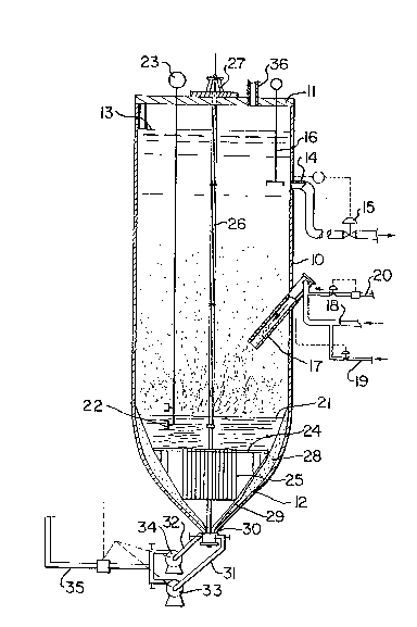
Figure l is a diagrammatic cross-section through an
apparatus according to the present invention.
Description of the Preferred Embodiments
One embodiment of the apparatus of the invention is
shown in Figure 1 and this is in the form o~ a relatively
tall vessel having a cylindrical portion 10 and a bottom
dished portion 12. In one successful industrial
embodiment, the vessel has a height of 23 m and a diameter
of approximately 8 m with a dished bottom. The vessel is
designed to operate at atmospheric pressure and is closed
by a cover plate ll, which is vented to the atmosphere via
vent 36. The walls and cover plate are preferably
insulated to prevent heat losses, reduce scale growth and
improve working conditions for the operating personnel.
:. , : ,., :
,' ' ~ .,
.
-6- ~ 9
A liquid level 13 is maintained in the vessel by
controlling flow rates. Clarified liquid is drawn oEf
from the vessel through an outlet 14 positioned below the
liquid level 13. Control valve 15 can be used to vary the
rate of discharge through outlet 1~ to maintain the liquid
level 13 at the desired level. The clarity of the liquor
is monitored by a clarity meter 16, which may be an
infra-red or ultrasonic detector.
The feed suspension is fed into the vessel through
inlet tube 17 which is directed in a downward slope into
the vessel, to direct the solids towards the center of the
vessel. This tube 17 is connected to a suspension inlet
line 18. It is desirable to maintain the temperature of
the feed suspension within quite close tolerances and this
temperature can be maintained by adding cooling liquor
from another process stream through inlet line 19. A
commercial flocculant is added to suspension feed line 18
by means of flocculant inlet line 20.
An interface 21 between slurry and clarified liquid is
carefully maintained at a predetermined level by means of
level sensors 22 and readout device 23.
In the dished section 12 there is provided a rotatable
rake mechanism 24 with downwardly extending arms 25
arranged in a triangular configuration to be positioned
relatively close to the inner conical wall of the vessel.
The rake 24 is rotated by shaft 26 and motor/gear
mechanism 27. This rake is similar to that disclosed in
U.S. Patent 4,830,507.
The rake is typically positioned with the arm
extremities about 15 to 30 cm from the inner wall of the
bottom section, but other clearances may be used. Between
the rake and the bottom section wall is a solids layer 28
consisting of stagnant mud. This mud is constantly
remolded by the rake arms, thereby constantly exposing
renewed surface 29 and preventing further build-up of
solids.
:: :
-7~ 3
At the bottom of the vessel is a discharge outlet 30
for discharging mud 28. Two draw off lines 31 and 32 are
shown with corresponding pumps 33 and 34. One of these
lines and pumps represents a spare. The outlets from the
pumps is discharged throush mud line 35.
In an alternative embodiment (not shown) of the
apparatus described above, the out:Let 14 is aligned with
the liquid level 13. With this arrangement, the outlet 14
is in the form of an uncontrolled gravity discharge and
the control valve 15 is eliminated. The remainder o~ the
apparatus remains as shown in Figure 1~
A preferred operating technique is illustrated by the
following example:
Example 1
A test was carried out using the apparatus shown in
Figure 1. The feedstock was a slurry obtained from the
Bayer process produced by digesting bauxite with caustic
solution to extract the alumina values. The feed slurry
had a density of 1.23 T/m and a solids content of 2.37%.
The feedstock was fed into the apparatus at a rate of
714 m /hr.
The caustic liquor contained 145 9/1 of dissolved
A12O3 and 220 g/l of total caustic, as Na2CO3.
The liquor temperature was 108C.
A flocculant was added with the feedstock. It was
100% anionicity sodium polyacrylate, available from Allied
Colloids under the trade mark ALCLAR 600.
The concentration of the flocculant solution was 1.6-2.5
g/l and it was added at a rate of 60 g/T of dry red mud.
This resulted in the flow rate of about 480 to 750 l/hr.
The cooling fluid which was added with the feedstock
was a caustic wash liquor and this was used at a variable
flow rate of 0 to 50 m3/hr. The cooling fluid had a
density of 1.12 T/m, a temperature of 50-60C and a
total caustic (expressed as Na2CO3) of about 100-120 g/l.
-
~, , ,:
:- ' :.
This arrangement provided an overflow through outlet
14 which was a clear liquor flowing at a rate of 684
m3/hr. The overflow liquor had a density of 1~22 T/m
and a solids content of 0.2% (200 mg/l). The temperature
of the overflow liquid was 106.5-107C.
The solids discharge through outlet 30 had a density
of 1.60 T/m and a solids content of 40%. This solids
underflow discharged at a rate of 30 m /hr and was at a
temperature of 105-106C.
Although the present invention has been described and
illustrated with respect to preferred features thereof, it
is to be unaerstood that various modifications and changes
may be made to the specifically described and illustrated
features without departing from the scope of the present
invention.
;