Language selection

Search

Patent 2027767 Summary

Third-party information liability

Some of the information on this Web page has been provided by external sources. The Government of Canada is not responsible for the accuracy, reliability or currency of the information supplied by external sources. Users wishing to rely upon this information should consult directly with the source of the information. Content provided by external sources is not subject to official languages, privacy and accessibility requirements.

Claims and Abstract availability

Any discrepancies in the text and image of the Claims and Abstract are due to differing posting times. Text of the Claims and Abstract are posted:

  • At the time the application is open to public inspection;
  • At the time of issue of the patent (grant).
(12) Patent Application: (11) CA 2027767
(54) English Title: CLOSURE AND/OR CONTROL ELEMENT FOR A METALLURGICAL VESSEL
(54) French Title: ELEMENT DE FERMETURE OU DE CONTROLE POUR CUVE DE METALLURGIE
Status: Deemed Abandoned and Beyond the Period of Reinstatement - Pending Response to Notice of Disregarded Communication
Bibliographic Data
(51) International Patent Classification (IPC):
  • B22D 41/16 (2006.01)
  • B22D 41/14 (2006.01)
  • B22D 41/18 (2006.01)
  • B22D 41/42 (2006.01)
  • F27D 03/14 (2006.01)
  • F27D 03/15 (2006.01)
(72) Inventors :
  • HINTZEN, ULLRICH (Germany)
  • LUHRSEN, ERNST (Germany)
  • SCHULER, ANDREAS (Germany)
(73) Owners :
  • DIDIER-WERKE AG
(71) Applicants :
  • DIDIER-WERKE AG (Germany)
(74) Agent: SMART & BIGGAR LP
(74) Associate agent:
(45) Issued:
(22) Filed Date: 1990-10-16
(41) Open to Public Inspection: 1991-04-18
Availability of licence: N/A
Dedicated to the Public: N/A
(25) Language of filing: English

Patent Cooperation Treaty (PCT): No

(30) Application Priority Data:
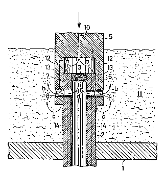
Application No. Country/Territory Date
P 39 34 601.3 (Germany) 1989-10-17

Abstracts

English Abstract


ABSTRACT
CLOSURE AND/OR CONTROL ELEMENT FOR A
METALLURGICAL VESSEL
In a closure and/or control element an inner tube (2)
has lateral openings (4). An outer tube (5) also has
lateral openings (8) and seats with a cylindrical
sealing surface (7) against a cylindrical sealing
surface (6) on the inner tube (2). In order to flush
the sealing surfaces (6,7) and the opening (8;4,8) with
inert gas, the inner tube (2) is provided at its top
with a closure (3), whereby a gas distribution chamber
(9) is formed. Inert gas introduced into the gas
distribution chamber (9) flows between the sealing
surfaces (6,7) and through the openings (8;4,8).
(Figure 1)


Claims

Note: Claims are shown in the official language in which they were submitted.


PA393?
CLOSURE AND/OR CONTROL ELEMENT FOR A
METALLURGICAL VESSEL
CLAIMS
1. Closure and/or control element for tapping liquid
metal melt from a metallurgical vessel including an
inner tube, which has lateral openings, and including
an outer tube, which also has lateral openings and
which seats against a cylindrical sealing surface on
the outer periphery of the inner tube with a
cylindrical sealing surface on its inner periphery, the
one tube being fixed and the other tube being movable
relative to it, characterised in that the inner tube
(2) is provided above its openings (4) within the outer
tube (5) with a closure (3), that the space between the
closure (3) and the outer tube (5) constitutes a gas
distribution chamber (9) for inert gas introduced
through the outer tube (5) and that the inert gas
passes out of the gas distribution chamber (9) between
the sealing surfaces (6,7) and passes through the
openings (8;4,8).
2. Closure and/or control element as claimed in claim
1, characterised in that the closure (3) is gas
permeable.
3. Closure and/or control element as claimed in claim
1 or 2, characterised in that extending within the wall
of the outer tube (5) are gas passages which discharge
into the openings (8) therein.
4. Closure and/or control element as claimed in One
of the preceding claims, characterised in that

extending within the wall of the inner tube (2) there
are gas passages (13,14) which discharge into the
openings (4) therein.
5. Closure and/or control elements as claimed in
claim 4, characterised in that the gas passages (13)
extend from the gas distribution chamber (9) to the
openings (4).

Description

Note: Descriptions are shown in the official language in which they were submitted.


2~77~
CLOSURE AND/OR CONTROL ELEMENT FOR A
METALLURGICAL VESSEL
DESCRIPTION
The invention relates to a closure and/or control
element for tapping liquid metal melt from a
metallurgical vessel including an inner tube, which has
lateral openings, and including an outer tube, which
also has lateral openings and which seats against a
cylindrical sealing surface on the outer periphery of
the inner tube with a cylindrical sealing surface on
its inner periphery, the one tube being fixed and the
other tube being movable relative to it.
Such a closure and/or control element is described in
DE-3540202 C1. Flushing with inert gas is not provided
in this specification.
WO 88/04209 A1 describes a stopper valve in which
sealing surfaces between a fixed portion and a movable
portion may be flushed with inert gas. The openings in
the movable portion can not be flushed through by the
introduction of inert gas.
It is the ob~ect of the invention to propose a closure
and/or control element of the type referred to above in
which the sealing surfaces and the openings may be
flushed with inert gas.
In accordance with the invention the above ob;eck is
solved in a closure and/or control element of the type
referred to above if the inner tube is provided above

2~7~7~
its openings within the outer tube with a closure, if
the space between the closure and the outer tube
constitutes a gas distribution chamber for inert gas
introduced through the outer tube and if the inert gas
passes out of the gas distribution chamber between the
sealing surfaces and passes through the openings.
Due to the fact that inert gas is passed between the
sealing surfaces, a gas cushion i5 produced there which
impedes wear of the sealing surfaces. Due to the
construction of the gas distribution chamber it is
ensured that the gas flows in uniformly between the
sealing surfaces over the entire periphery of the inner
tube.
The inert gas flows away through the openings into the
melt. It thus reduces the wear of the edges of the
openings. The inert gas also avoids material adhering
to the openings.
The inert gas flowing into the melt also promotes the
deposition of impurities from the melt and the
homogenisation of the melt. It is favourable thàt the
gas flows in countercurrent to the melt flowing into
the openings.
In one embodiment of the invention the closure is gas
permeable. A portion of the inert gas then flows
through the closure into the inner tube. The remaining
portion of the inert gas flows in between the sealing
surfaces. The gas permeable closure results in inert
gas flowing not only through the openings in the inner
tube but also through those of the outer tube.

In a further embodiment there are extending within the
outer tube gas passages which discharge into the
openings therein. The openings are thus flushed
through not only by the gas current which has passed
between the sealing surfaces but also by an additional
gas current. Extending within the wall of the inner
tube there can be gas passages which discharge into the
openings therein. The gas flow through the openings
may thus be increased.
Further advantageous embodiments of the invention will
be apparent from the following description of an
exemplary embodiment. In the drawings:
Figure 1 is a schematic sectional view of a closure
and/or control element of a metallurgical vessel with a
fixed inner tube and movable outer tube, and
Figure 2 shows an embodiment with a fixed outer tube
and movable inner tube.
Secured to the base 1 of a metallurgical vessel is an
inner tube 2 of refractory, ceramic material. The
inner tube 2 is closed at its upper end by a closure 3.
In the exemplary embodiment the closure 3 is
constituted by a gas permeable insert. The closure 3
can be constructed integrally with the inner tube 2 and
be gas impermeable. Provided below the closure 3 in
the wall of the inner tube 2 are openings 4.
Axially pushed onto the inner tube 2 is an outer tube 5
of refractory, ceramic material. The outer tube 5 and
the inner tube 2 butt against one another at

~2~7~7
-
cylindrical sealing surfaces 6,7. The outer tube 5 has
openings 8. It is axially movable and/or rotatable
about the common longitudinal axis with respect to the
inner tube 2, whereby the openings 4,8 are adjustable
with respect to one another to control the passage of
the melt.
Between the outer tube S and the closure 3 there is a
gas distribution chamber 9. A gas passage 10 extending
within the outer tube 5 discharges into it.
If inert gas, such as argon, is introduced into the gas
distribution chamber 9, then this flows in the
direction of the arrows a between the sealing surfaces
6,7. The gas flows in part in the direction of the
arrows b through the openings 8 into the melt 11; the
gas flows in part in the direction of the arrows c at
the bottom of the outer tube 5 into the melt 11.
A further portion of the gas flows out of the gas
distribution chamber 9 through the closure 3 into the
inner tube 2 and flows in the direction of the arrows d
through the openings 4,$ irto the melt 11. In the open
position of the closure and/or control element shown in
the Figure, melt 11 flows through the openings 8,4 into
the inner tube 2 and flows downwardly out of the
latter. The gas flows through the outflowing melt 11
in the openings 4,8 in countercurrent.
The wear of the sealing surfaces 6,7 and of the
openings 4,8 is reduced by the described gas flows.
Furthermore, adhesion of the melt 11 in the openings
4,8 is impeded.

2~2 1~'7~7
In order to improve a directed gas flow through the
openings 4,8, further gas passages 12,13,14 can be
provided in the wall of the inner tube 2 and/or the
wall of the outer tube 5. These are shown in chain
lines in the Figure. The gas passages 12 extend within
the wall of the outer tube 5 from the gas distribution
chamber 9 to the openings 8. The gas passages 13
extend within the wall of the inner tube 2 from the gas
distribution chamber 9 to the openings 4. The gas
passages 14 extend within the wall of the inner tube 2
from below the base 1 to the openings ~.
In the exemplary embodiment of Figure 2, the outer tube
2 is arranged on the base 1 of the metallurgical
vessel. The inner tube 2 is pushed into the outer tube
5 from below. It is axially movable and/or rotatable
about the common longitudinal axis with respect to the
outer tube 5.
The gas distribution chamber 9 is present within the
outer tube 5 above the closure 3 of the inner tube 2.
:
The flushing of the sealing surfaces 6,7 and of the
openings 4,8 with inert gas is effected as has been
described above in connection with the exemplary
embodiment of Figure 1.

Representative Drawing
A single figure which represents the drawing illustrating the invention.
Administrative Status

2024-08-01:As part of the Next Generation Patents (NGP) transition, the Canadian Patents Database (CPD) now contains a more detailed Event History, which replicates the Event Log of our new back-office solution.

Please note that "Inactive:" events refers to events no longer in use in our new back-office solution.

For a clearer understanding of the status of the application/patent presented on this page, the site Disclaimer , as well as the definitions for Patent , Event History , Maintenance Fee  and Payment History  should be consulted.

Event History

Description Date
Inactive: IPC from MCD 2006-03-11
Time Limit for Reversal Expired 1997-10-16
Application Not Reinstated by Deadline 1997-10-16
Deemed Abandoned - Failure to Respond to Maintenance Fee Notice 1996-10-16
Application Published (Open to Public Inspection) 1991-04-18

Abandonment History

Abandonment Date Reason Reinstatement Date
1996-10-16
Owners on Record

Note: Records showing the ownership history in alphabetical order.

Current Owners on Record
DIDIER-WERKE AG
Past Owners on Record
ANDREAS SCHULER
ERNST LUHRSEN
ULLRICH HINTZEN
Past Owners that do not appear in the "Owners on Record" listing will appear in other documentation within the application.
Documents

To view selected files, please enter reCAPTCHA code :


To view images, click a link in the Document Description column (Temporarily unavailable). To download the documents, select one or more checkboxes in the first column and then click the "Download Selected in PDF format (Zip Archive)" or the "Download Selected as Single PDF" button.

List of published and non-published patent-specific documents on the CPD .

If you have any difficulty accessing content, you can call the Client Service Centre at 1-866-997-1936 or send them an e-mail at CIPO Client Service Centre.

({010=All Documents, 020=As Filed, 030=As Open to Public Inspection, 040=At Issuance, 050=Examination, 060=Incoming Correspondence, 070=Miscellaneous, 080=Outgoing Correspondence, 090=Payment})


Document
Description 
Date
(yyyy-mm-dd) 
Number of pages   Size of Image (KB) 
Drawings 1991-04-17 2 57
Claims 1991-04-17 2 40
Abstract 1991-04-17 1 16
Descriptions 1991-04-17 5 145
Representative drawing 1998-07-05 1 27
Reminder - Request for Examination 1997-06-15 1 122
Fees 1994-09-21 1 74
Fees 1995-09-20 1 78
Fees 1993-09-22 1 56
Fees 1992-09-17 1 23