Note: Descriptions are shown in the official language in which they were submitted.
~ ~ ~,.J, j
SMII 0101 PUS -1-
CAR~ON D~80RPTION ~BATER
TECHNICAL FIELD
This invention relates to a carbon desorption
heater for use in a system for removing volatile organic
contaminants from a carbon filter.
BACKGROUND ART
One way of removing volatile organic
contaminants from industrial exhaust stack emissions is
through the use of a carbon filter that absorbs the
volatile organic cont~;n~nts prior to passage of the
emissions to the atmosphere. Such carbon filters are
supplied with heated gas from a carbon desorption heater
to remove the volatile organic contaminants from the
carbon filter by a desorption process. This type of
system is conventionally constructed with the carbon
filter as a rotatable wheel that is rotatively driven
between emission and desorption partitions spaced
angularly from each other so as to provide the removal
of cont~ ts from the emissions during one angular
portion of rotation and to provide the desorption of the
cont~ ln~nts by the heated air at another angular
portion of the rotation. After passage through the
carbon filter, the heated air has a concentration of
volatile organic contaminants many times greater than
that of the exhaust stack emissions such that the
volatile organic cont~ ;nAnts can be more efficiently
incinerated prior to passage of the products of
combustion to the atmosphere.
Carbon desorption heaters presently used with
industrial paint spray booth emissions cleaning are not
particularly efficient or easy to use since such heaters
~ V h ~ ~ ~
SMII 0101 PUS -2-
are assembled from numerous components at the factory
site due to their relatively large size. Such
inefficiency and the cost involved in assembly of the
heaters at the factory site necessarily must be born by
the cost of the resultant painted product.
DISCLOSURE OF lNV~:Nl'lON
An object of the present invention is to
provide an improved carbon desorption heater for use in
a system for removing volatile organic contaminants from
a carbon filter. In carrying out this object, the
improved carbon desorption heater has increased
efficiency, is easy to use, and is readily fabricated
prior to shipment for assembly from a ;ni ~1 number of
modules at the site where the heater is to be used.
The carbon desorption heater of the invention
is designed for use in a system for removing volatile
organic ccntaminants from a carbon filter. A housing of
the heater has an inlet for receiving air to be heated
and has a supply outlet through which heated air is
supplied to the carbon filter to provide the removal of
volatile organic contaminants. A recirculating heating
circuit of the heater is located within the housing and
includes a recirculation blower that moves air in a
recirculating manner along the heating circuit as well
as including a burner that heats the air during its
recirculating flow. The heating circuit also includes
an exhaust stack outlet through which a portion of the
recirculating air is exhausted during each cycle of flow
through the heating circuit. A heat exchanger of the
heater is located within the housing and has a first
flow path that is heated by the recirculating heating
circuit. ~ second flow path of the heat exchanger is
heated by heat exchange with the first flow path.
J ;i
SMII 0101 PUS -3-
delivery blower of the heater is located within the
housing and moves air through the second flow path of
the heat exchanger for heating thereof and for supplying
the heated air to the supply outlet of the housing for
the flow to the carbon filter from which the volatile
organic contaminants are received.
Provision of the recirculating heating circuit
of the heater provides efficiency in the heating of the
air that removes volatile organic contA inAnts from the
carbon filter during the desorption process prior to
incineration of contaminated air and eventual passage of
the products of such incineration to the atmosphere.
In its preferred construction, the carbon
desorption heater also includes a combustion blower that
draws air intc the heating circuit for combustion at the
burner. An inlet conduit of the heating circuit is
positioned between the burner and the housing to
function as insulation that prevent excessive heating of
the housing by the burner, and the combustion blower
draws air into the heating circuit through the inlet
conduit for combustion at the burner.
Ductwork of the heating circuit preheats the
air upon entering the housing prior to moving through
the second flow path of the heat exchanger for further
hea_ing.
The carbon desorption heater is preferably
construction to include a plurality of modules each of
which is sufficiently small so as to be shippable by
commercial carrier. These modules are securable to each
other at the site where the heater is to be used and are
also preferably prewired and prepiped to reduce the
installation time and cost.
7~'JJ~_i
SMII 0101 PUS -4-
In its preferred construction, the housing of
the heater includes insulated walls that define a
heating chamber in which the recirculating heating
circuit is located. An outer wall of the housing
cooperates with the insulated walls to define a control
chamber and has an access opening through which the
control chamber is accessible to permit maintenance and
adjustment of the heater without being subjected to the
environment. Each blower of the heater includes a drive
motor located within the control chamber such that the
motors are not operated at an elevated temperature as
would he the case if located within the heating chamber.
One of the insulated walls of the housing has an access
door for providing access to the heat exchanger from the
control chamber. A floor of the control chamber has a
grate that embodies the air inlet to the housing, and
the housing also includes a control chamber ceiling
having a filter through which the air passes upon flow
from the inlet through the control chamber into the
heating chamber in which the recirculating heating
circuit is located.
In its pre~erred construction, the heating
chamber of the heater has a pair of spaced end portions
and a connecting portion that connects the end portions
to define a generally U-shaped configuration. This U
shaped heating chamber defines a central portion at
whiçh the control chamber is located. The recirculating
heating circuit of the heater has an L-shaped lower
heating reach that extends along one end portion of the
heating chamber and the connecting portion, and the
burner of the heating circuit is located along this
lower heating reach. The heat exchanger of the heater
is located at the junction of the other end portion and
the connccting portion of the heating chamber with the
3 lower heating reach of the heating circuit extending to
~ w ~ 1 ~ iJ ~f
SMII 0101 PUS -5-
the heat exchanger for providing heated gas flow through
its first flow path. An L-shaped upper return reach of
the heating circuit extends from the heat exchanger
along the connecting portion of the heating chamber to
its one end portion along which the lower heating reach
also extends. At this one end portion of the heating
chamber, the heating circuit has a vertical connecting
reach that connects the heating and return reaches.
The preferred construction of the carbon
desorption heater also has the exhaust stack outlet
provided with a connection to the lower heating reach
of ths heating circuit upstream from the burner and
within the one end portion of the heating chamber. The
supply outlet and delivery blower of the heater are
preferably located at the other end portion of the
heating cha~ber.
Control of the supply of heated air i5
preferably achieved by a damper that controls the extent
of heated air supplied from the second flow path of the
heat e~chAnger to the supply outlet. A vertical outlet
duct of the heater extends upwardly from the delivery
blower at the other end portion of the heating chamber
to the supply outlet through which the heated air is
supplied.
~ The objects, features, and advantages of the
present invention are readily apparent from the
following detailed description of the best mode for
carrying out the invention when taken in connection with
the accompanying drawings.
J 3
SMII 0101 PUS -6-
BRIEF DESCRIPTION OF DRAWINGS
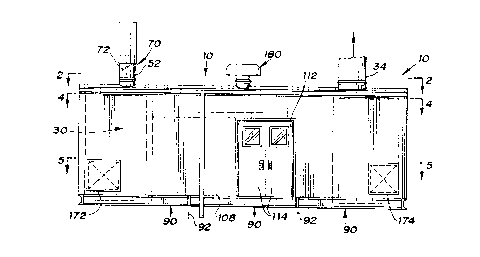
FIGURE 1 is a front elevational view of a
carbon desorption heater constructed in accordance with
the present invention;
FIGURE 2 is a plan view of the heater taken
along the direction of line 2-2 in Figure 1 and
illustrates the modular construction of the heater;
FIGURE 3 is a schematic view of a system in
which the heater is utilized to remove volatile organic
cont~ inAnts from a carbon filter;
FIGURE 4 is a plan view taken in section
through the heater along the direction of line 4-4 in
Figure 1 to illustrate the heater construction adjacent
its ceiling level;
FIGURE 5 is a plan view taken in section
through the heater along the direction of line 5-5 in
Figure 1 to illustrate the heater construction adjacent
its floor level;
FIGURE 6 is an elevational view taken in
section through the heater along the direction of line
6-6 in Figure~ 5 and illustrates both a heating chamber
and_a control chamber of the heater;
FIGURE 7 is an elevational view taken in
section through the heater along the direction of line
7-7 in Figure 4 and also illustrates both the heating
and control ch~ 'crs of the heater; and
FIGURE 8 is a schematic view illustrating the
flow paths through a heat exchanger of the heater.
SMII 0101 PUS -7-
BEST MODE FOR CARRYING OUT THE INVENTION
With reference to Figures 1 and 3 of the
drawings, a carbon desorption heater constructed in
accordance with the present invention is generally
identified by 10 and is used in a system 12 shown in
Figure 3 for removing volatile organic cont~ in~nts from
a carbon filter 14. This carbon filter 14 is rotatively
driven as indicated by arrow 16 and receives exhaust
stack emissions from an exhaust stack 18 such as of the
type used with an industrial paint spray booth for which
this heater 10 has particular utility. .hese emissions
from the exhaust stack 18 are received by the rotating
carbon filter 14 within a stationary partition 20 such
that volatile organic cont~ inAnts are removed from the
emissions by absorption within the carbon filter. At
another stationary partition 22, the carbon filter 14
receives heated air through a supply conduit 24 from the
heater 10 so as to remove the volatile organic
contaminants from the carbon filter 14 by a desorption
process. This heated air passes through the carbon
filter 14 and is received by an incineration stack 26
whose burner 28 provides incineration of the volatile
organic contaminants prior to passage of the products of
combustion to the atmosphere. This type of carbon
filter desorption system provides the gases within the
stack 26 with a concentration of volatile organic
contaminants many times greater than the concentration
within the e~haust stack 18 such that the incineration
of those contaminants can be accomplished more
efficiently than burning within the exhaust stack 18.
As shown by the schematic illustration of
Figure 3, the heater 10 includes a housing 30 having an
inlet 32 for receiving air to be heated and also having
a supply outlet 34 through which heated air is supplied
SMII 0101 PUS -8-
to the carbon filter through the conduit 24 as
previously described. A recirculating heating circuit
3 6 of the heater is located within the housing 30 and as
indicated by arrows 38, 40, and 42 receives combustion
air from the housing inlet 32. This heating circuit 36
includes a recirculation blower 44 that moves air as
shown by arrows 46 and 48 in a recirculating manner
along the heating circuit. A burner 50 of the heating
circuit 36 heats the air during this recirculating flow,
while an exhaust stack outlet 52 of the heating circuit
receives a portion of the recirculating air which is
exhausted as shown by arrows 54 and 56 during each cycle
of flow through the heating circuit. Heater 10 al~o
includes a heater exchanger 58 having a first flow path
60 that is heated by recirculating heating circuit 36
and having a second flow path 52 that is heated by heat
exchange with the first flow path through any
conventional type heat exchanger construction. A
delivery blower 64 of the heater moves air as shown by
arrows 66 and 67 into and through the second flow path
62 of the heat exchanger 58 for heating thereof and for
supplying the heated air as shown by arrow 68 to the
supply outlet 34 of the housing.
Recirculation of the gas within the heating
circuit 36 provides efficiency in the heating of the gas
supplied to the outlet 34 since heat that is not
exchanged throl-gh the indirect heat exchange process
within the heat exchanger 58 after passage through its
first flow path 60 is not completely wasted by passage
to the exhaust stack outlet 52 as with conventional
carbon desorption heaters. Rather, almost all of this
heat is recouped by the recirculation of the air within
the heating circuit 36 as shown by arrows 46 and 48 back
to the burner 50. The extent to which the gas is
exhausted from the heating circuit 36 is governed by a
h ~ ') ;3
SMII 0101 PUS -9-
control 70 that is preferably embodied by a damper 72
within the exhaust stack outlet 52 as shown in both
Figures 1 and 3. The fresh air drawn into the heating
circuit 36 during each cycle, as illustrated by arrow 42
and as is hereinafter more fully described, replaces the
air exhausted through outlet 52 such that the
recirculating flow does not become excessively
concentrated with the products of combustion.
As illustrated in Figures 3 and 5, the
recirculating heating circuit 36 also includes a
combustion blower 74 that draws air as shown by arrows
42 and 76 into the heating circuit 36 for combustion at
the burner 50 as is more fully hereinafter described.
Heating circuit 36 includes ductwork generally
designated by 78 for preheating the air within the
heater housing 30 prior to being moved through the
second flow path 62 of the heat exchanger 58 for further
heating. Thus, the flow of the air along this ductwork
78 prior to entering the heat exchanger provides greater
efficiency in the entire heating process.
As illustrated in Figures 3, 5 and 7, the
heatin~ circuit 36 also includes an inlet conduit 80
which is po~itioned as best illustrated in Figure 7
between the burner 50 and the housing. More
specifically, this inlet conduit 80 has an L-shaped
cro~s section best shown in Figure 7 extending along the
outer side and bottom of th~ heating circuit adjacent
the burner 50 so as to prevent concentration of the heat
~rom the burner at the outer and lower sides of the
housing. This inlet conduit 80 as shown in Figures 3
and 4 has an entry end 82 where the combustion air
enters the heatiny circuit ~6 adjacent the heat
exchanger 58 as shown by arrow 66. Adjacent the burner
50 as illustrated in Figure 5, the inlet conduit 80 has
i sJ ~)
SMII 0101 PUS -10-
an exit end 84 where the combustion air turns at a right
angle as illustrated by arrow 86 for flow to the
combustion blower 74 and delivery therefrom through a
feed conduit 88 to the burner 50 for combustion with gas
supplied to the burner.
As illustrated in Figures 1, 2 and 4 through
6, the carbon desorp ion heater 10 includes a plurality
of modules 90 connected to each other by unshown
connectors at interfaces 92. Each of these heater
modules 90 is sufficiently ~mall so as to be shippable
by commercial carrier, and the modules are securable to
each other at the site where the heater is to be used,
such that fabrication of the heater can be done prior to
shipment to ~he use site for assembly. As illustrated,
1~ there are three of the heater modules 90; however, it
should be appreciated that any nu~ber of the modules can
be utilized depending upon the size of the heater and
shipping size limitations.
As illustrated in Figures 4 through 7, the
housing 30 includes insulated front walls 94, insulated
side walls 96, an insulated rear wall 98 and insulated
inner walls :L00 that cooperate with an insulated floor
102 and an insulated ceiling 104 to define a heating
chamber 106 in which the recirculating heating circuit
36 is located. Housing 30 also includes a front outer
wall 108 that cooperates with the insulated inner walls
100 to define a control chamber 110 from which the
heater is controlled by an operator. This outer wall
108 has an opening 112 that is selectively opened and
closed by the doors 114 shown in Figures 1 and 5 so as
to permit access through the opening into the control
chamber. This control chamber 110 is maintained
generally at ambient temperature to facilitate the
operation of the heater whils- the heating chamber 106 is
J ~
SMII 0101 PUS -11-
heated by the recirculating heating circuit 36 without
substantial loss of heat due to the insulated wall
construction of the heater as described above.
As illustrated best in Figure 5, the heater
blowers 44, 64, and 74 previously described have
associated motors 116, 118 and 120, respectively, that
are located within the control chamber llO so as to be
maintained generally at ambient temperature while having
the necessary rotary and/or ductwork connections to the
recirculating heating circuit 36 so as to permit the
heating to be performed within the heating chamber 106
at its elevated temperature.
As best illustrated in Figures 4 and 5, one of
the insulated inner walls 100 has an access door 122 for
providing access from the control chamber 110 to the
heat exchanger 58 within the heating chamber 106. This
access door 122 is selectively opened and closed to
provide the access for maintenance and repair of the
heater exchanger 58 and to also isolate the heating and
control chambers 106 and llO during use of the heater.
Furthermore, a~ shown in Figure 5, the housing 30 also
preferably includes a floor track 123 along which the
hea~er exchanger 58 is moved from thP heating chamber
106 through the control chamber 110 and out through the
access door o]pening 112.
As illustrated by combined reference to
Figures 6 and 7, the heater housing includes a control
chamber floor 124 having a grate 126 that embodies the
air inlet 32 through which the air enters the housing as
illustrated by arrows 38 for the heating as previously
described. Heater housing 30 also has its control
chamber 110 provided with a ceiling 128 having a filter
130 through which air flows from the control chamber as
h ~ J - '
SMII 0101 PUS -12-
shown by arrows 132 into the heating chamber 106 in
which the recirculating heating circuit 36 is located.
Thls air flows from the filter 130 as shown by arrows
132 toward the left and, as shown in Figure 4, makes a
right angle turn as shown by arrow 134 for flow along
the ductwork 78 of the recirculating heating circuit, as
was previously described, to provide the preheating of
the air prior to entsring the heat exchanger 58 for
further heating and eventual delivery to the supply
outlet 34.
As illustrated in Figures 4 through 7, the
heating chamber 106 has a pair of spaced end portions
136 and 138 and a connecting portion 140 that connects
the end portions to define a generally U-shaped
1~ configuration. This U-shaped configuration of the
heating chamber defines a central portion in which the
control chA ~cr 110 is located. Thus, the insulated
inner walls 100 extend along each end portion 136 and
138 and along the connecting portion 140 of the heating
chamber so as to provide close proximity access to each
portion of the heating ch~ ~er from the control chamber
110 for maintenance and operation of the heater.
As best illustrated in Figure 5, the
recirculating heating circuit 36 has an L-shaped lower
heating reach 142 that extends along the one end portion
136 of the heating chamber and along the connecting
portion 140 of the heating chamber with the burner 50
located along this lower heating reach. The heat
exchanqer 58 as shown in Figures 4 and 5 is located at
the junction of the other end portion 138 of the heating
cha~ber and the connecting portion 140 of the heating
chamber. As shown schematically in Figure 8, the lower
heating reach 142 extends as shown by arrow 144 to the
heat exchanger 58 for flow of the heated air through the
J ~ 'J ~
SMII 0101 PUS -13~
first flow path 60 of the heat exchanger in an upward
direction and exits the air from the heat exchanger for
return flow as shown by arrow 146. This upward flow of
the heated air through a conventional indirect heat
exchange operation provides heating of the second flow
path 62 in which air preheated by the ductwork of the
heating circuit is further heated after entry as shown
by arrow 66 from the heating chamber into the heat
exchanger and downward flow through the second flow path
62 prior to exiting as shown by arrow 148 for the
delivery to the supply outlet as previously described.
As illustrated in Figure 4, the heating
circuit 36 also has an L-shaped upper return reach 150
that extends from the heat exchanger 58 along the
connecting portion 140 of the heating chamber to the one
end portion 136 so as to provide return of ths
recirculating air after its passage through~the heat
exchanger as previously described. At the one end
portion 136 of the heating chamber as best illustrated
in Figure 6, the heating circuit 36 has a vertical
connecting reach 152 through which the recirculated air
flows downwardly from the upper return reach 150 to the
lower heating reach 142 under the impetus of the blower
44 previously described. The exhaust stack 52 as shown
in Figure 5 has a connection 154 to the lower heating
reach 142 of the heating circuit upstream from the
bur~er 50 at the one end portion 136 of the heating
chamber.
As illustrated by reference to Figure 6, the
supply outlet 34 and the delivery blower ~4 are located
within the end portion 138 of the heating chamber on the
opposite side of the control chamber 110 from the
heating chamber end portion 136 where the vertical reach
152 extends between the heating and return reaches 142
~ I J ~.
SMII 0101 PUS ~14-
and 150. A delivery duct 156 provides a connection
between th~ heated air received from the heat exchanger
58 for flow to the blower 64 and eventual delivery to
the supply outlet 34. A damper 158 also illustrated
schematically in Figure 3 is located along the delivery
duct 156 and provides control of the extent of heated
air supplied from the heat exchanger 58 to the supply
outlet by permitting introduction of less heated air
within the heating chamber end portion 138 into the
blower 64. This damper 158 is operated by a control
assembly 160 that extends through the adjacent insulated
wall 100 into the control ch~ ~er 110 for manual and/or
automatic adjustment as necessary to maintain the
desired temperature of the gas supplied to the outlet
34. Usually, this damper 156 is opened when the
temperature of the heated air at supply outlet 34 is too
high, and the air drawn in through the opened damper
thus reduces the temperature at the supply outlet. A
vertical duct 162 extends upwardly from the blower 64
withîn the heating chamber end portion 138 to the supply
outlet 34 through which the heated air is supplied.
Within the heating chamber 106, the ductwork
78 of the recirculating heating circuit 36 includes
access doors 164 and 166 as shown in Figure 4 and access
doors 168 and 170 as shown in Figures 5 and 7 for
permitting necessary access to the interior of the
heating circuit for cle~n;ng and repair. Likewise, the
housing 30 has access doors 172 and 174 as shown in
Figures 1, 5 and 7 for providing access to the heating
chamber end portions 136 and 138 respectively adjacent
the recirculating ~lower 44 and the delivery blower 64
previously described.
Within the control chamber 110 where the
blower motors 116, 118 and 120 are located as previously
h
SMII 0101 PUS
described, a control panel 176 is also providPd as is a
gas supply 178. As shown in Figures 1 and 7, a vent 180
is also provided on the housing roof 182 so as to
provide ventilation within the control chamber 110, and
a light fixture 184 is suspended from the roof 182
adjacent the vent and provides illumination within the
control chamber 110.
As illustrated in Figure 6, the insulated
inner walls 100 have access doors 186 and 1~8 for
permitting blower removal for maintenance and repair.
These blowers are driven by their associated motors
through belt and shaft drive assemblies 190 and 192
located within the control chamber 106.
As illustrated in Figure 7, one of the
insulated inner walls 100 has an access door 194 for
providing access to the burner 50 along the lower
heating reach 142 of the recirculating heating circuit
36. This burner 50 has an H-shaped construction and
includes a profile plate 196 having an H-shaped opening
198 fox restricting the air flow along heating reach 142
to adjacent the burner 50 in order to increase the
efficiency oi' the burner flame heating the air.
Whi.le the best mode for practicing the
invention has been described.in detail, those familiar
wit~ the art to which this invention relates will
recognize various alternative designs and embodiments
for practicing the invention as defined by the following
claims.