Note: Descriptions are shown in the official language in which they were submitted.
~ SUR&E ARRESTER WITH RIGID INSULATING HOUSING
- ~, ' '.
BACKGROUND OF THE INVENTION ~ -
,.
~ Field of the Invention
The invention i5 directed to the field of surge
arres~ers used to protect high voltage systems from the
effects of overvoltage incidents created by lightning
strikes and more particularly to the construction of
such surge arresters to prevent injury to personnel or
equipment due to the catastrophic failure of such surge
arresters during overvoltage incidents.
'z
~ Description of the Prior Art
'l In surge arresters of the prior art, MOV blocks
are stacked together and capped at each end with a fitting
} including a threaded stud. The block and cap stack is
then placed in an ela~tomeric housing through an open
end with one of the studs projecting from the housing
closed end for connection ~o a support or connector probe.
A metal cap is fixed over the open end of the housing
wi~h the second stud projecting ther~through for connection
to a ground conductor. Although the elastomeric housing
~upporting the cap is locally weakened to encourage the
downward movement of fragments of the MOV blocks and
,~ , ~
~ r ''~ t ' - ~ "
i
~ fittings should these elements fracture due to catastrophic
i failure of the arrester, the elastomeric housing possesses
insufficient strength to prevent the scattering of
fragments, contain them and Eorce them downwardly to
! 5 minimize injury to persons in proximity to the arrester
or nearby equipment.
In U.S. Patent No. 4,404,614 issued September 13,
1983, a surge arrester made up of a number of blocks 30
is placed in an EPDM rubber housing 12. To add structural
integrity to the arrester "an inner tubular liner 36
is disposed concentrically within and extending the entire
length of chamber 14 between the internal components
of the latter and the inner surface of the housing 12.
This liner is constructed of a material having a high
~t 15 bursting strength, preferably resin-impregnated fiberglass
.i (specifically epoxy resin-impregnated filamen~-wound
fiberglass). An intermedia~e sleeve 38 is disposed con-
centrically between and extends the entire length of
3~ liner 36 and the inner surface of housing 12. This sleeve
is constructed of a moisture-impervious material preferably
.i glass flakes in an epoxy matrix."
Such an arrangement provides added strength but
fails to provide an air-free non-electrically ionizable
~: environment about the arrester blocks to minimize internal
'.,'`-- ':'
.~,~
~ r. r . ~
- .
electrical arcing which can lead t:o block destruction
during overvoltage incidents.
The patent to Thuillier, U.S. Patent No. 4,864,456
issued September 5, 1989, shows a lightning arrester which ~-~
.
~, 5 uses a filament winding to provide radial binding without
significant axial compression. "The filament winding
thus has the sole function of holding the pellets together ;~
~ . . ." It also adheres to the pellets and the spacers
.!' but because of the undulating surface of pellets and
, 10 spacers, the air is not eliminated within housing 5 or
between the winding 4 and the pellets 1 and spacers 2. ;-~
~! To provide a surge arrester having excellent heat
transfer properties and improved tensile and cantilever
,.. ~ . ~. .~
strengths, U.S. Patent No. 4,656~555 issued April 7, 1987,
;~ 15 uses a wrap of filament windings 14 over MOV blocks 11, --
i~ 12 and terminal pieces 16, 18 before insertion in a ~
:"1 .; :
weathershed housing 20. The arrangement of windings 14- --
~l and blocks 11, 12 are not sealed against the intrusion
of air therebetween. --
Bergh et al., U.S. Patent No. 4,467,387 issued August
.. ~ .
21, 1984, shows a wound tube 22 of glass fibers in bonding
resin but spaced from blocks 42 by elastomeric sleeves
42a and resilient balls 44. Air can be entrapped adjacent
the blocks 42 inside the insulative tube 22. U.S. Patent -
- 3 -
:`'.,~ ~:'
", . . ..................... . . , . . . ............. - - -
. ,.. , ~ . . , . .. :
2e2~3]6
No. 4,851~955 issued July 25, 1989, to Doone et al shows MOV blocks
2 in a glass-reinforced plastic shell 5 within heat-shrink sleeve
6. Shell 5 is bonded to the outer surfaces of MOV blocks 2, heat
sink/spacer blocks 3 and 5 terminal blocks 4.
5SUMMARY OF THE INVENTION
The inventicn in one broad aspect provides a surge arrester
comprising at least one cylindrical metal oxide varistor block
having a first end and a second end and an outer peripheral surface
between the first end and the second end, two metal end fittings,
10one adjacent each of the first and second ends, a rigid dielectric . ~ ~
insulating tube having an inside diameter larger than the outer - -.:
diameter of the outer peripheral surface of the block and a ~-
dielectric material layer between the interior surface of the tube - ` -
and the outer peripheral surface of the block to completely fill ~.
15the space between the tube and the at least one varistor and the ~ -
end fittings. The material layer extends beyond the ends of the - -
tube and over at least a portion of the free end surfaces of the
. .: - .
end fittings to seal the end fittings and the block and lock the ~ --
tube thereto.
20Another aspect of the invention provides the method of making -.-`: `:
a surge arrester comprising the steps of placing a rigid insulating
tube of a predetermined inside diameter about and spaced apart from
a cylindrical metal oxide varistor block having an outside diameter - :-
less than the predetermined inside diameter of the tube and filling
~........ .
- 4 -
.~
2 Q 2 ~ ~ ~ :
~` the interstices between the inside diameter of the tube and the
outside diameter of the block with a dielectric insulating layer to
prevent the existence of air therebetween.
More particularly, the present invention overcomes the
~; 5 difficulties present in prior art devices and manufacturing
techniques by replacing the in-situ formation of epoxy-impregnated
filament windings used to assemble a stack of MOV blocks and end
- fittings and provide structural integrity to the stack with a
preformed and tested epoxy-impregnated filament winding tube of
selected dimensions and strength and which can be positioned with
respect to the stack to contain same and to establish a desired
I direction of movement of fragments of such blocks should same
catastrophically fail durlng overvoltage incidents. Additionally,
the tube can be formed by two or more tube segments, laid end to
end but not mechanically joined other than by the filler set forth
below. A filler of a suitable dielectric insulating material such
as a thermoset or thermoplastic material, an epoxy or a liquid
crystal polymer is injected between the MOV blocks and the tube to
fill the interstices establishing an air-free non-electrically-
ionizable environment. The filler is permitted to extend beyond
and engulf the tube and a portion of the end fittings to provide a
rigid, sealed assembly.
, Accordingly this invention seeks to provide an improved surge
arrester.
A 5
.~
"i,, " , ~ , . . .
.~,................................................. . . . .~ .. ~ . , - - : :
Further this inventlon seeks to prov:ide an improved surge
`~ arrester employing MOV blocks and end fittings with a rigid
.,;
~`! insulating housing, preferably comprising a rigid tube of wound
. ~ .
epoxy-impregnated fiberglass filaments so positioned with respect
`~' 5 to the MOV blocks of the arrester as to est:ablish a direction of
movement of fragments of the blocks in the event the blocks fail
, during voltage overload incidents.
.~ Still further the invention seeks to provide an improved surge
arrester employing MOV blocks and end fittings with a rigid
insulating housing comprising a rigid tube of wound epoxy~
impregnated fiberglass filaments, the interstices between the outer
.. surfaces of the blocks and end fittings and the tube being filled
with a dielectric insulating material to provide an air-free, non-
~ electrically ionizable environment and to rigidify the assembly by
`f'~, 15 engulfing the tube and end fittings to form a unitary assembly.
Other aspects and features of the invention will be pointed
~ out in the following description and claims and illustrated in the
'~ accompanying drawings which disclose, by way of example, the
principles of the invention and the best mode which has been
contemplated for carrying it out.
: . - - . -~:: - -
BRIEF DESCRIPTION OF THE DRAWING
In the drawing in which similar elements are given similar
reference characters~
-~ ,' ~: ' ` '~;- '
- 6 - ~
, - ' -:
. . . -.
; ,; . ~ ~ - . . -
~ ~ ~ J ~, ~ 3 ~J ~ ~
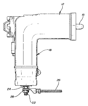
Fig. 1 is a side elevation of a surge arrester in
the form of a high voltage elbow connector constructed
in accordance with the concepts of the invention. ~ ~
Fig. 2 is a sectional view of the connector of Fig. 1. : -
Fig. 3 is a side elevational view of an alternative
construction of the rigid tube of Fig. 2.
DESCRIPTION OF THE PREFERRED EMBODIMENT
' Turning now to Figs. 1 and 2, there is shown a surge ~ :
arres~er 10 in th~e form of a high voltage elbow connector : -~
constructed in accordance with the concepts of the inven~
tion. Although the surge arrester construction is shown - .
~ housed in an elbow configuration as used in the underground j.
,¦ distribution of high voltage currents, it is equally
I applicable to terminators and ~ransmission line supports
! 15 and protectors for above-ground transmission or distribu- ~ `-
~ tion lines and circuits.
¦ A body 30 of resilient, non-tracking insulating . .-
material such as EPDM rubber or butyl rubber is formed : :~
in a generally L-shape with a horizontal leg 12 and a
vertical leg 18. A shielding layer 32 of conductive
material such as semi-conductive EPDM rubber or butyl
rubber is placed over a major portion of body 30 (see
Fig. 2). Leg 12 is tapered to form a receptacle 14 to
7 :
,'` ' ~-.~
i' '
:.., ~. :. :: -
, .
. . .
;, . ~ ~ .
h ~ ~"-~
:` :
` receive therein the interface of a bushing insert (not -~
``~ shown) and probe 16 is arranged to engage with the female
;`` contact thereof in known manner. The female contact
?,
(not shown) engages the probe 16 and extends within recep~
tacle 14 of leg 12. The elbow connector is locked to
the bushing insert by engagement of annular detent rib
44 with an annular recess in the bushing insert (not
' shown). The end 46 of vertical leg 18 is sealed with
! a metal cap 20. The metal cap 20 is connected via met-
allic coupling 62 to the reinforced surge arrester assembly
72 with the intention that it separate from leg 18 or
fracture to permit the contents of leg 18 to move down~
-~ wardly as will be described in detail below.
Within leg 18 is a bore 36 extending substantially
lS the entire length of leg 18 and terminating at one end
in a reduced bore 38 communicating with bore 34 of leg
j 12. At the opposite end, bore 36 extends through end 46
i~ of leg 18 and in turn communicates with bore 42 extending
through cap 20. A first metallic coupling 48 having
;~ 20 a central portion 50 positioned in bore 38 and internally
threaded as at 52 to receive the externally threaded
I portion 54 of probe 16. The externally-threaded portion
56 is threaded into an internally threaded aperture 58
A
of end fitting 60. -
.,
- 8 -
R~
", . ~
`~ L', ~; S~
.
'`; : :.' '
:`"` '~,
:`
A second metallic coupling 62, having a central ~-
.. . .~. .
~- portion 64, is positioned in bore 36 adjacent cap 20 ~ -
and has an externally-threaded portion 66 threadably -~
engaged with internally-threaded aperture 68 of end fit~ing
70. A second externally-threaded portion 22 extends
through bore 42 in cap 20, plate 23, and is engaged by
- a first nut 24 providing a large contact area. A ground
:3 ~- .
conductor 26, having a suitable fitting 27, may be fixed ~
l , :-:`
in place against nut 24 by a second nut 28. `~ --
Within cavity 36 is placed the reinforced surge - ~-
arrester assembly 72 according to the present invention. -~
The surge assembly 72 consists of a number of metal oxide
varistor (MOV) blocks 74, of the type commercially avail- -~-
~' able from Meidensha for example, and preferably comprise - -;
zinc oxide non-linear resistor material such that they
31 become highly conductive in the presence of high voltages ~ ;
" as during a lightning strike and return to their normal
Zl; high resistance condition uncler normal voltage levels.
Although three blocks 74 are shown, the number and size -~
of blocks employed will depend upon the circuit rating
.'J ~ ` , . .
1 as is well known. -
! A first metallic end fitting 60 is placed at the
top of the stack of blocks 74 adjacent block 74a and
'
g _
'"Z
;:
;-Z
:`~
a second metallic end fitting 70 is placed at the bot~om
of the stack of blocks 74 adjacent block 74c. These
end fittings 60, 70 are made of any suitable metal and
preferably from aluminum. The interfaces be~ween each
of the blocks 74a, 74b and 74c and of the blocks 74a,
~ 74c and end fittings 60 and 70, respectively, are filled
i.~ with a conductive adhesive 76 such as a silver epoxy
paste. A preformed rigid tube 78 is placed about but
not in contact with the blocks 74 and end fittings 60,70.
End 82 of tube 78 is positioned above the top surface
90 of end fitting 60 to provide a relatively stronger
region adjacent end fitting 60 as compared to the region
adjacent end fitting 70 and thus establish a preferred
downward direction of movement for any fragments of the
assembly 72 sbould it fracture as hèreinafter described.
In addition, the preformed rigid tube 92, as shown
,~ in Fig. 3, may be made up of two or more segments such
; as 94 and 96 laid end to end, in line but not joined
except for the filler layer as set out below. This seg~
menting increases the tendency of assembly 72 to move
downwardly particularly below the line of contact 98
of segments 94, 96. Tube 78 is formed of filament windings
of any suitable continuous fiber such as nylon, rayon,
- 10 -
~.,.
~.t'J~i C~
``( ':
, :' '',
glass and polyethylene. Other fibers such as cera~ic
~i~ fibers may be used although a glass filament winding
is preferred. The filament windings may be in the form
of a single fiber or each winding may be comprised of
many smaller strands. The filament windings are impreg-
nated with a resinous material which may be natural or
synthe~ic and may be in the partially cured or uncured
, . .:~ -
!- state. Epoxy resins are preferred. The resins arP fully
cured so that the resulting tube 78 is rigid. The inside
diameter of tube 78 is made greater than the outside
diameter of the blocks 74 and end fittings 60, 70.
The end fittings 60, 70 are connected to a suitable
fixture using threaded apertures 58 and 68 and the stack
of blocks 74 and end fittings 60, 70 are placed inside
, 15 of and spaced from the inside walls of tube 78 and the
7' entire assembly placed in a mold cavity. The interstices
s are now filled with a suitable dielectric insulating
material such as a thermoset or thermoplastic resin such
as glass-filled nylon by injection molding. The material
fills all space between the outer surface of the blocks 74
,i and ~he inner surface of tube 78 to form a filler layer
84 which provides an air-free, non-electrically ionizable
environment. The filler layer is also permitted to extend
;' beyond the ends 80, 82 of tube 78 and overlie such ends
:i ~
. , .
' ~
~ t S r ~
80, 82 to lock tube 78 to filler layer 84. In the case
of the segmented tube 92, filler layer 84 also serves
to hold segments 94, 96 in position. Further, ends 86
of filler layer 84 overlie most of the exposed surface
.
9Q of end fitting 60 while ends 88 overlie most of the
exposed surface 71 of end fit~ing 70 to seal assembly
72. The relative dimensions of the components are as
follows: for MOV blocks, l-inch thick, end fittings
~-inch thick and, disregarding the thickness of the glue
j 10 layers 76, tube 78 will be 3~ inches long and filler
layer 84, ends 86 and 88 will be 4~ inches in length.
The MOV blocks 74 are 1~ inches in diameter, the tube
78 will have an outside diameter of 1~ inches and is
62 mils thick and the filler layer 84 will be approximately
~5 62 mils ~hick.
Assembly 72 will now have couplings 48 and 62 as-
sembled to end ~ittings 60 and 70, respectively, and
a metal mandrel will be fixed to coupling 48 with a semi-
conductive EPDM rubber insert 85 chemically bonded to
' 1 . :
and covering coupling 48; the resulting assembly will
be placed in a suitable mold cavity. Insulative EPDM 1
rubber 30 will now be injection molded between the resul-
ting assembly and a semi-conduc~ive EPDM rubber 32 to
complete the surge arrester 10 providing an air-free -
.'i ~ .
~7, -12 - `~`-
. ~ -. - .
-
non-electrically ionizable environment between assembly 72
and the electrically-grounded semi-conductive EPDM rubber
of cap 20 and shield 32.
Due to the high hoop strength provided by tube 78,
5 it acts as a pressure vessel which contains or deflects
any fragments of the MOV which may result from a failure
of the blocks during voltage overload ins~ances. The
open end of tube 78 in concert with the upward displacement
of tube 78 relative to the top of the stack of blocks 74
10 results in a natural downward direction of movement from
assembly 72 of any hi~h energy fragments of exploding
MOV blocks which cannot be contained within body 30.
Segmenting of the tube 92 enhances the preferred downward
direction of movement of assembly 72. Also, the lack of
!15 mechanical connection of cap 20 to leg 18 permits the
downward movement of any fragments of the MOV blocks 74,
'/ the tube 78, filler layer 84 in vertical leg 18.
1 The MOV blocks 74 may fail due to the establishment
.~ . of a short circuit arc in the blocks due to overvoltages
. ~;,
20 caused by a lightning strike or the follow current flowing ::~
into the blocks after the strike. The elimination of ~:
the air about the blocks 74 minimizes such arcs and pro~
vides an air-free, non-electrically ionizable environment
- 13 -
. : -
'`'S1 : : `:
~ `''``."`
~`
~` for the MOV blocks 74 to reduce caltastrophic failures -
of the blocks during overvoltage incidents and thus mini-
mize injury to persons working in the area of the arrester
or damage to adjacent equipment.
~ 5 While there have been shown and described and pointed
,~i out the fundamental novel features of the inven~ion as
applied to the preferred embodiment, it will be understood
that various omissions and substitutions and changes : :
of the form and details of the device illustrated and
in its operation may be made by those skilled in the
~ art without departing from the spirit of the invention. :
,'il . -
...
,.,, . ~
. "
i! . -:-: :: .
':~ .. ' , ,.,. '
~; ~"`'.`'.'
~'., ' `. ', - `
- 14 - -~
: ~ -. .
~, .........
;~j , . ~ .