Note: Descriptions are shown in the official language in which they were submitted.
20289~5
"MUNICIPAL WASTE THERMAL OXIDATION SYSTEM"
Technical Fiel~
This invention relate~ to lncinerators, and more
particularly to an air-starved, batch burn, modular
municipal wa~te thermal oxldation system.
2028~5
Back~round Art
Munic~pal waste is materlal dlscarded from resldentlal,
commercial, and some Industrial establlshments. The amount
of waste generated In the year 2000 19 expected to be In the
range of 159 to 287 mllllon tons per year, compared to
estimates of current generatlon rates of 134 to 180 milllon
tons. The most common method currently used to dlspose of
munlelpal waste 19 dlreet landflll. However, exlstlng
landflll capacity 19 belng exhausted In many areas of the
eountry and new landfills are becomlng Increa91n91Y
dlfficult to slte. Because of these problems wlth dlre¢t
landflll, Increàsed emphasls wlll be made on reduelng waste
volume through combustlon.
There are three basic types of facllltles used to
combust munlcipal waste. The predomlnant type 19 ealled
"mass burnR because the munlelpal waste 19 eombusted wlth a
prlorlty on consumlng large amounts of material through-put.
The eombustors at mass burn faellltles usually have overfeed
stoker type grates. These combustors are fleld ereeted and
Indlvldual eombustors can range In slze from 500 to 3,000
tons per day of munlclpal waste Input. A second type of
faclllty 19 the modular combustor. Modular combustors are
typieally shop-fabrlcated and range In slze from 5 to 100
tons per day. A third method for eombustlng munlelpal waste
is procesalng It to produce refuse derlved fuel ~RDF), then
eombustlng the RDF In a waterwall boller. RDF offers the
advantage of producing a more homoqeneous fuel and
... . ~, .
Inereaslng the percentage of munlclPal waste whleh 19
reeyeled.
--2--
-
2028~5
Almost all existing facilities have some type of
partlculate matter emission controls. Many exiYting modular
combustors attempt to control particulate matter using a
two-stage combustion proceYs, most of these facillties also
have add-on controls. Other facilities u~e add-on controls,
such as ESPs, dry scrubber~, wet scrubbers, and baghouses.
Almost all new faclllties will have add-on particulate
controls such as ESPs and baghouses. In addition, a
9i gnificant number may include acid gas controls. However,~
total emiYsions from MWC are stlll expected to increase due
to the large increase in the total capacity of the
population.
Those concerned with these and other problems recognize
the need for an improved municipal wa~te incinerator.
- 3
20Z89~5
Dlsclosure of the Inventlon
The present Inventlon provldes an alr-starved, batch
burn, modular, municlpal waste Inclnerator. It 1~ de~lgned
to burn unsorted loads of heterogeneou~ materlals ln
quantltles ranglng from 5 to l,000 tons per standard elght
hour day. The unique aspect of thls system deslgn 19 that
through research In air mixlng, alr turbulence, and
temperature control, lt 19 possible to burn thls materlal
with a hlghly favorable stack emlsslon product, wlthout the
need for bag houses, dry scrubblng, or other elaborate down
~tream air processlng equlpment. The thermal oxldatlon
system Includes a prlmary oxldatlon chamber connected to a
secondary combustlon unlt by a gas transfer tube. Flammable
gases created In the prlmary chamber are completely burned
In the secondary combustlon unlt. The gases pass upwardly
through the alr mlxlng rlng and tangentlally dlsposed
re-lgnltlon burners. The tangentlal orlentatlon of the
re-lgnltlon burners forms pllot flame through whlch the
combustlon gases travel before exltlng from the stack. The
ceramlc cup Immedlately above the pllot flame creates a hlgh
temperature envlronment and entralns the gas stream for up
to 5.5 seconds. Both the temperature and dwell tlme are
adjustable by the system process controller.
An object of the present Inventlon 19 the provlslon of
an Improved munlclpal waste Incinerator.
Another ob;ect 18 to provlde a munlcipal waste
Inclnerator that 19 slmple In deslgn and durable and
economlcal to supply.
A further object of the Inventlon 18 the provlslon of a
municlpal waste Inclnerator that can be efflclently and
~ ' ~` f ~ ~
. . .
2028~15
safely operated without sophiYticated engineering or
managerial support.
Still another object iY to provlde a municipal waste
incinerator that has a rapid process cycle, thus minimizing
problems of insect and rodent infestation, odors and
scattering of trash.
A still further object of the present lnvention is the
provision of a municlpal waste incinerator that minlmlzes
the adver~e impact on the environment by produclng a clean
stack alr emisslon product and by providlng for recovery of
recyclable glass chard, ferrou~ and non-ferrous metals, and
ash resldue for use as number one concrete aggregate,
asphalt addltlve, or lnert flll material.
20Z8~5
Brlef Descrl D tlon of the Drawlnas
These and other attrlbutes of the Inventlon wlll become
more clear upon a thorou~h study of the followlng
descrlption of the best mode for carrylng out the lnventlon,
partlcularly when revlewed ln con~unctlon wlth the drawings,
where~ns
Flg. l 19 a schematlc flow dlagram Illustratln~ typlcal
Inputs and outputs of the municlpal waste Inclnerator of the
present Inventlon;
~lg. 2 19 a perspectlve vlew showlng the exterlor of
one pos~ible embodiment of the lncinerator whereln the
prImary combustlon chamber 19 connected to the secondary
combustlon unit by the gas transfer tube;
Flg. 3 19 a sectlonal elevation vlew of the prlmary
combustlon chamber;
~ Ig. 4 19 a sectlonal plan vlew of the prlmary
combustlon chamber taken along llne 4-4 of Flg. 3 showlng
the f loor mounted combustlon alr supply llnes;
Fl~. 5 19 a sectlonal elevatlonal vlew of the ~econdary
combu~tlon unlt;
Flg. 6 19 a sectlonal Plan vlew of the secondary
combustlon unlt taken along llne 6-6 of Flg. 5 ~howlng the
orlentat~on of the air mixlng rlngs and
Flg. 7 19 a sectional plan vlew taken along llne 7-7 of
Flg. 5 showing the orlentatlon of the re-lgnltlon burners
posltioned Immedlately above the alr mlxlng rlng.
20Z8~5
Best Mode for C~rrYina Out the Inventlon
Referrlng now to the drawlngs, whereln llke reference
numerals designate ldentlca1 or correspondlng part~
throu~hout the several vlews, Flas. 1 and 2 show a munlclpal
waste Inc~nerator (10) Including a prlmary combustlon
chamber (12~ and a secondary combustlon unlt (14)
interconnected by a gas transfer tube (16).
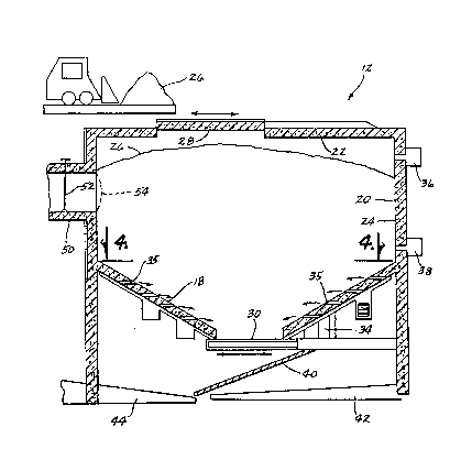
As best Yhown In Flgs. 3 and 4, the prlmary combustlon
unlts or pods (12) are all of Identlcal constructlon~
however, to accommodate dlfferent volumes, they maY be
supplled ln dlfferent slzes. They arc a panel steel
fabrlcatlon for the floor (18), walls ~20), and top ~22),
wlth slx Inches of A.P. ~reen refractory llnlng ~24) on all
Interlor surfaces. The pane!s are on-slte assembled. Waste
material (26) 19 Ignlted and combusted In thls chamber ~12)
after be~na batch loaded to the approxImate level shown In
Flg, 3.
Dependlng on the slze of the pod ~12), there are one,
two, three or four access doors ~28) In the top ~22) for
loadlng waste materials ~26). These doors ~28) may be
hydraullcally operated, and are refractory llned steel
fabrlcatlons. The door closlng sequence may be automatlc
wlth safety and manual overrldes. When fully closed, the
door ~ welght mechanlcally sealJ the door agalnst a ~pun
glass barrler ~not shown) to prevent the e~cape of ga~
durlng the combu~tlon process. The door ~28~ 1~ not
physlcally latche~ Into place, provldlng exploslon rellef In
the unllkely event that any slgnlflcant amount of explo~lve
materlal would be placed In the chamber.
2028~5
Other acces~ to the prlmary combustlon unlt (12) 1~
provlded for the removal of non-combustlble materlal, such
as steel, glass, plaster, etc. These doors (30) are slmllar
In constructlon to the top access panels (28~ and are part
of the slde panel fabrlcatlons. These doors (30~ and those
doors (28~ In the top of the pod (12~ must be fully closed
before the Ignltlon process can begln, Thls functlon 19
controlled automatlcally through the central operatlons
control room ~not shown).
Combustlon alr IY Introduced Into the pod (12~ through
a series of floor mounted stalnless steel supply llnes (32~.
Each supply llne (32) lnclu~e~ a number of horlzontal or
downwardly dlrected ports (35) whlch supply alr to the pod
(l2~. Slnce the ports (35~ are horlzontal or downwardly
dlrected they do not flll wlth materlal and become plugged.
The llnes (32~ are connected to an alr compressor (34~ whlch
feeds addltlonal alr lnto the pod (12~ as dlctated by the
combustlon actlvlty. Upper lgnltlon burners (36) and lower
lgnltlon burners (38) are spaced around the walls (20>. Alr
addltlons or restrlctlons are regulated by computer In the
central operatlons room.
Upon completlon of the burn, a flne ash powder and
larger pleces of steel, glass, and rock are left In the pod
(12). The clean out access door (30~ 19 opened and the
uncombusted materlal drops down on screen ~40). Flnes or ash
fall through the screen (40~ to the flnes conveyor (42~ and
lar~er slze materlal 19 removed by the sortlng conveyor
(44~.
A large dlameter connectlon transfer tube (60~ dlvert~
gas formed durlng prlmary combustlon Into the secondary
2028 9 15
combustion unlt (14). The tube ~50) 19 a cyllndrlca1 steel
fabrlcatlon wlth six inches of refractory llnlng (24), There
19 a ~teel damper (52) in the center of thls tube. The
damper (52) 19 electronlcally or manually operated and 19
used to control alr flow from the prlmary unlt (12) to the
secondary unit ~14) for the purpsoe of regulatlng combuotlon
actlvity. A cage ~54) covers the openlng where the tube (50)
connect~ to the prlmary unlt (12).
Once the waste material ~26) 19 loaded, all access
10 doors (28 and 30) to the pod (12) are sealed, and the
i~nltlon sequence beglns. Propane or natural gas fIred
Ecllpse burners (36 and 38~ are used to Ignlte the materlal.
The duration of the prlmary lgnltlon burn 19 determlned by
the composltlon of the waste (26), and the lnternal
temperature of the pod (12). Thls 19 regulated automatlcally
through the control system. The number of Ecllpse lgnlters
(36 and 38) per pod (12) 1~ dependent on the overall pod
dlmenslons such that there 19 sufflclent Ignlter capaclty to
evenly Ignlte the upper surface area of the waste charge
20 ~26). The lgnlters ~36 and 38) automatlcally re-engage lf
there 19 stll1 materlal remainlng ln the pod ~12) and lf the
Internal temperature of the pod (12) fal 18 below 760 F, A~
the materlal (26) ln the pr~mary combustlon unlt (12) burns,
there 19 no vislble flame. Essentlally, the solid materlal
(26) 19 converted to a gas under temperature. As the ~as
material 19 formed, It i~ vented through the tran~fer tube
~50).
As most clearly shown In Flg. 5, gas from the prlmary
combustlon unit ~12) enters lnto the ga~ accumulatlon
chambér (60) by the draft created ln the hlgher cells of the
20289 1 5
secondary combustor (14). Thls chamber (60) provldes a
collectlon polnt for the fluctuatlng gas volumes comlng from
the prlmary combustlon process. Thls 18 a steel fabrlcatlon
wlth refractory llnlng (24), as are the other component~
whlch were previously discussed.
As be~t shown ln Elgg. 5 and 6, outslde alr 19 drawn
lnto the sy~tem wlth electric blowers (62) through a steel
duct assembly (64) whlch surrounds the outer caslng of the
secondary combustor (14). The alr ls pressurlzed In thls
duct ~64~, and dlverted under pressure through a serle~ of
1.5 lnch dlameter tubes (not shown) lmbedded ln the choke
and alr mlxlng rlng (66). Thls rlng (66) 19 ceramlc
fabrlcatlon 5.5 feet ln dlameter by 10 lnches thlck, wlth an
Inslde dlameter of 8.5 Inches. The pres~urlzed gas movlng
through the 8.5 Inch dlameter throat of the mlxlng rlng
mlxes wlth the outslde alr, thls comblned alr and gas forms
an alr cone slx Inches above the rlng wlth a focal polnt of
two Inches In dlameter.
At the focal polnt of the alr/gas mlxture, slx lnches
above the center of the mlxlng rlng (66) four Ecllpse
Ignltlon burners ~70) are located. The four are orlented at
90 degrees, but the force of the flame 19 dlrected about 30
degreeQ off of center to the counter clockwlse ~Ide. Tho
effect of thls posltlonlng 1~ to cause the completo
re-lgnltlon of any non-combusted gas In the alr stream, and
to cau~e the alr stream to rope sllghtly, and to lncrease
the turbulence of the alr column. Thl~ Improves the alr mlx,
and Increases the retentlon tlme of the alr column ln the
Ignltlon cell. Outslde alr 1~ used as propellant for the
natural gas or propane burners. Thls Increases the avallable
--10--
2028~15
mixlng alr volume, and contrlbutes to the ~cuttlng torch"
effect of thls ~ytem.
Followlng the re-lgnltlon of the gas stream, lt enters
an Ignltlon cell or expanslon chamber (72) to provlde
controlled resldence tlme at hlgh temperatures. Thls chamber
(72~ contalns the llve flame and provldes a hlgh eemperature
envlronment for the ~as stream. As wlth other part~ of the
system, thls is a ~teel fabrlcatlon wlth 9 Ix lnches of
refractory llnlng (24~. An lnverted ceramlc cup (73) 19
posltloned lmmedlately above the burners (70) to create a
hlgh temperature envlronment and entraln the gas ~tream for
up to 5.5 seconds. Both the temperature and the dwell tlme
are adiustable by the ~y~tem process controller.
Under some condltlons where certaln materlals are belng
I5 burned, heavy metal~ and acld formatlon can re-comblne ln
the alr stream after the secondary combustlon process. To
effectlvely remove these contamlnants when necessary, a wet
scrubber can be lnstalled ln-llne above the expanslon
chamber (72). To convey the alr stream from the bulIdln~
houslng the lnclnerator (10), the stack (74) 19 mounted on
elther the wet scrubber or at the exlt port of the Ignltlon
cell or expanslon chamber (72) as the Installatlon dlctates.
The stack (74) 18 a double walled 12 ~auge steel
fabrlcatlon, wlth acce~s ports (not shown) for alr sampllng
at two, four and slx dlameters of helght. Access to the
ports 19 provlded on an lndlvldual In~tallatlon ba~ls.
A reflux llne (75) includln3 a flow valve and meter
- ~76) extends from the stack ~74) and selectlvely returns a
portlon of the gas ~tream to the alr supply llnes (32) of
the prlmary combustlon chamber (12).
--11--
,'1~ `, :` ~
2028~15
In operation, with the bottom door (30) closed and
sealed, waste materlal ~26) 19 loaded lnto the prlmary
combustlon chamber ~12) to an approxlmate level as Indlcated
ln Flg. 3. The loadlng door ~28) 18 then closed and sealed.
5 In the secondary unlt <14), the blower (62) 19 actlvated for
about three minutes to purge gas resldues to the atmosphere.
The re-lgnltlon burners ~78) are then actlvated untll the
lnternal temperature reaches about 500 F. The secondary
unlt ~14) 19 thus pre-heated to Ignlte the gas flow that
wlll be comlng from the primary unlt ~12). The top set of
lgnitlon burnero ~36) in the prlmary unlt ~12) are then
actlvated and continue to run untll the pod temperature
reaches 250 F. The damper ~52) 19 opened to allow about ten
percent flow through the transfer tube ~50).
The temperature In the prlmary combuotlon chamber ~12)
19 kept around 250 F. by actlvatlng the lower lgnltlon
burners ~38) and/or provlding forced alr through the ports
~35). The damper <52~ lo adjusted to provide~a flow of 6ao
to the secondary combustlon unlt ~14) at the maxlmum gas
flow rate the secondary unlt (14) wlll handle whlle havlng a
favorable stack emlsslon.
To control the qualIty of otack emlsslons, the
temperature ln the expanslon chamber 19 malntalned In a
range from about 1800 F. to 2500 F. Thls 19 accompllshed
by slmultaneous control of the damper (52) whlch regulates
the volume of feed gas coming through the transfer tube, the
supply of fuel to the re-lgnltlon burner3 ~70), and the
electrlc blowers ~62) whlch regulates the alr volume In the
alr mlxlng rlng ~66~.
-12-
2028~5
~xAMpr~ I
A serles of computer runs were completed where alr
9Uppl led to the prlmary combustlon unit varled from 125%
excess alr over stolcholmetrlc to a 50% defIclency. The
calculated flame or combustlon temperature varled from 1343
F. at 125% exces~ alr up to 2224 F. for the stolchlometrlc
a~r. For the alr starved runs, the temperature decreased as
the alr decrea~ed. At a 50% alr deflclency, the calculated
temperature ~n the primary combustlon unlt wa~ 978 F. These
computer runs a~sume that all of carbon In the garbage 19
converted to carbon dloxlde and carbon monoxlde. If there 19
any unburned carbon In the ash, as there probably wlll be
under alr starved condltlons, the combustlon temperatures
wlll be lower than that predlcted by the computer runs.
The gases from the prlmary combustlon unlt were fed to
the secondary combustlon unlt for those runs where the
prlmary combustlon unlt operated under a deflclency of alr
(runs 4-21). A pllot flame of natural ga~ (mostly methane,
composltlon 24.66~ hydrogen and 75.34% carbon and heat of
20 combustlon of 23011 BT W lb) was fed to the secondary
combustlon unlt to In~ure Ignltlon. The natural gas was used
as fuel for the secondary combustlon unlt for the purPose of
the computer runs, but the fuel quantlty added was ~et equal
to zero 90 It would not add to the-mass and energy balance.
When the secondary combustlon unlt was operated at 20%
exce~s alr, a 2260 F. to 2378 F. temperature was achleved.
When the alr wa~ Increased to 125% excess, the temperature
In the secondary combustlon unlt decrea~ed to about 1700 F.
In actualIty, when the prlmary combustlon unlt 19
burned wlth a deflclency of alr, conslderable soot wlll form
-13-
2028~1S
and the ash wlll llkely contaln unburned carbon. The result
wlll be less carbon monoxlde avallable to the secondary
combustion unlt. The secondary combustlon unlt temperature
will therefore be le~s than that predlcted by the computer
runs.
The gas detention tlme in the secondary combustlon unlt
can be calculated from the gas flow (actual cublc feet per
mlnute) and the secondary combustlon unlt volume (38.9 cublc
feet). For a 10000 ACFM flow, the detentlon tlme ls
calculated to be 4.5 - 5.25 seconds. The detentlon tlme
requlred for de~tructlon of products of Incomplete
destructlon 19 also a functlon of how well the alr, fuel,
and off-ga~es from the prlmary combustlon unlt are mlxed at
the flame.
For runs 13-16, the percent excess alr In the pod was
varled at a 1815 Ibs/hr burn rate untll a 1000 F.
temperature was achleved. Thls was calculated to occur at a
-40.7% excess alr rate. Then, uslng the -40.7% excess alr
rate, the resultlng temperature at burn rates of 1500, 2000
and 2500 Ibs/hr was calculated (Runs 17, 18, and 19). The
result was a hotter temperature as the feed rate or burn
rate Increased. For run 20, lt was a~ d that 80~ of the
carbon ln the feed would be burned and the rest would remaln
ln the ash. For run 21, lt was assumed only 60% of the
carbon would be burned. The result of unburned carbon was
lower temperdtures ln the primary and ~econdary combustlon
unlt.
Table 1, below, summarlzes these computer runs.
2028~5
Table 1. Summary of Computer Runs
Prlmary Combustlon Unlt Secondary CombuJtlon Unlt
5 Run % Ash % Excess Temp. F ~as Flow % Excess Temp. F Gas Flow
In feed Alr ACFM Alr AC~M
124.11% 125 1343 11952 -- -- --
224.11% 20 1953 9231 -- -- --
324.11% 0 2224 8834 -- -- --
424.11% -10 1931 7362 20 2262 9105
524.11% -20 1632 5998 20 2272 9286
624.11% -30 1359 4829 20 2338 9660
724.11% -40 1038 3661 20 2375 9938
824.11% -50 978 3160 20 2378 10100
924.11% -50 978 3160 60 2034 10209
1024.11% -50 978 3160 125 1733 10879
11 35% -50 925 2607 125 1702 9190
12 35% -50 925 2607 20 2311 8449
13 100% -43 911 3263 20 2366 9950
14 100% -35 1217 4276 20 2377 9870
15 100% -41 991 3515 20 2366 9920
16 100% -40.7 1003 3553 20 2366 9917
17 lOOS -40.7 957 2844 20 2306 8021
18 100% -40.7 1022 3966 20 2391 11026
19 100% -40.7 1049 5048 20 2433 13984
80% -37 984 3113 20 2086 7527
21 60% -29 976 2746 20 1765 5331
Feed Rate~: Run 17: 1500 Ibs/hr
Run 18: 2000 lb~/hr
Run 19: 2500 I bs/hr
All other run~: 1815 lb~/hr
- I 5 ~
2028~5
F~AMPF.~ 2
Emlsslons testlng was conducted for the followlng
series of test burns In the munlclpal waste Inclneratlon
system prototype.
Test 1 = Wood, paper materlal, cardboard
1. 1,115 pounds raw materlal welght;
2. Length of burn - 8 hours, 7 mlnutes;
3. Propane fuel consumptlon = 50 gallons;
4. Post-burn ash recovery = 30 pounds;
5. Percent reductlon by welght = 97.31%.
Test 2 = Lawn debrls, vegetatlon, hay, apples
1. 888 pounds raw materlal welght;
2. Length of burn = 8 hours, 40 mlnutes;
3. Propane fuel consumptlon = 130 gallons;
~ 4. Post-burn ash recovery ~ 97 pounds;
5. Percent reductlon by welght = 89.1S.
Te~t 3 = Truck and automoblle tlres
1. 1,464 pound~ raw materlal welght;
2. Length of burn - 8 hours, 7 mlnutes;
3. Propane fuel consumPtlon = 45 gallons;
4. Post-burn ash recovery ~ 247 pounds
(118 pounds steel beltlng, 129 pounds
ash~;
5. Percent reductlon by welght = 88.13%.
. ~
2028~5
Test 4 ~ Mlxed resldentlal trash (19% plastlc~ by
welght)
1. 1,271 pounds raw materl`al welght~
2. Length of burn = 7 hours, 55 mlnutess
3. Propane consumptlon = 70 gallons;
4. Post-burn ash recovery = 79 pounds
(52 pounds ash, 15 pounds glass, 6 pounds
metal);
5. Percent reductlon by welght ~total) -
93.8%;
Percent reductlon by welght (ash only) -
96.0%.
Summary Data
Total materlal burned = 4,738 pounds:
15 Average welght per test = 1,184.5 pounds:
Average burn tlme = 8 hours, 18 minutes;
Total ash recovery = 453 pounds (ash, glass, metals);
Average recovery of ash per burn = 113.25;
Percentage reductlon by welght ~ 90.44%.
As shown ln Tables 2 and 3 below, low levels of
partlculates and carbon monoxlde ln the stack gases was
lmpresslve. The hlghest partlculate emlssion measured for
any of the burns was 0.17 pounds per hours (2.1 mllllgrams
per standard cublc feet) durlng the tlre burn, and that
25 emlsslon was reduced slgnlflcantly by proper adJustment of
fuel and alr to the secondary combustlon unlt. When the
burner controls were adJusted properly, there was no vl~lble
stack plume nor notlceable odor.
The N0x emlsslons were prlmarily a functlonn of
30 temperature ln the secondary combustlon unlt. For test burns
--17--
-
2028~5
3 and 4, the N0x could be controlled at under 60 parts per
million. Sulfur dioxide and chloride emissions were
prlmarlly a function of the sulfur content and chloride
content of the garbage burned.
Table 4 below, summarizeY the trace metal analysis of
the ~tack ga~. -
18
2028~?~5
TAhle 2.
Stack Emisslons (Average of Measurements Durlng Test)
C0 Nx S2 Chlorides Partlculates
5 Test ppm ppm ppm ppm mg/SCF
1 21 42 not detected O.B 1.0
2 28 51 not detected not measured 1.1
3 33 59 72 5.4 1.6
4 26 59 10 21.2 0.9
Units: ppm = parts per million by volume;
m~/SCF = mllligrarns per standard cubic foot of stack
gas, dry basiY, 70F. and 1 atm;
Chlorldes reported as equivalent HCI, detectlon
limlt 0.4 ppm.
1 9-
r ,~
20Z8~5
Table 3.
Particulate Emission ReYults
Test Sample %H20 %C02 Lbs/Hr m~dsf
1 1 lS.4 12.100 0.068 0.81
2 1 9.17 8.856 0.063 0.83
Z 2 7.13 6.043 0.073 0.39
2 3 8.68 9.648 0,.098 1.27
3 1 0.96 7.416 0.078 0.88
3 2 8.80 6.348 0.166 2.03
4 1 15.18 6.616 0.0647 0.91
4 2 9.96 5.251 0.0641 0.79
4 3 9.92 5.788 0.0635 0.82
Note: mg/dsf = mllligrams particulate per dry Ytandard
cubic feet of flue gas;
IbY/hr = pounds per hours of particulate;
~H2O and %CO2 = actual volumetric percent measured
during the tst ~averaged value);
Test 2 - Sample 1 = this test discarded due to
developed leak in the sampling
system.
~EPA particulate emiYsion standard for an inclnerator of
this type iY 0.08 grains/dscf. The average value for this
test series is 0.024 grains/dscf, or 0.125% of the allowable
emission rate.)
-
2028~5
TAhle 4.
Metals In Flue Gas Captured by Fllter
Test 3 Te~t 3 Test 4 Test 4 Test 4
Metal Sample 1 Sample 2 Sample 1 Sample 2 Sample 3
Sllver(Ag)<0.00003 <0.00003<0.00003 <0,00003<0,00003
Aluminum~AI) 0.000088 0.00013 0.00022 0.00035 Indeter
Arsenlc(As)a <0.0003 <0.0003 <0.0003 <0.0003 <0.0003
Boron~B) 0.00029 0.00008 0.00007 0.00011 Indeter
Barlum(Ba)<0.00003 <0.00003<0.00003 <0.00003<0.00003
Berylllum~Be) c.00003<0.00003 <0.00003<0.00003 <0.00003
Calcium(Ca)0.0018 0.0011 0.0028 0.0020 0.0004
Cadmlum(Cd)<0.00003<0.00003 0.00006 0.00020 0.00004
Cobalt(Co)<0.00003 <0.00003<0.00003 <0.00003 0.00006
Chromlum(Cr) 0.000035<0.00003 <0.00003<0.00003 0.00242
Copper(Cu~<0.00003 <0.00003'0.00018 0.00009 0.00006
Sodlum(Na)Indetermlnate 0.0045 0.0099 0.0060 0.0004
Iron(~e) 0.0259 0.0003 0.00006 0.00048 0.0104
Potasslum(K) <0.01 <0.01 <0.01 <0.01 ~O.Ol
Llthlum~Ll)<0.00003<0.00003<0.00003 <0.00003<0.00003
Magneslum(Mg) 0.00009 0.00008 0.00014 O.OOOll 0.00006
Manganese(Mn) 0.00021<0.00003 <0.00003 0.00005 0.00067
Molrbd~r- (Mo) .00003 <0.00003 Indetermln.<0.00003 <0.00003
NlckeltNI)0.00021 0.00005 0.00004 0.00004 0.00206
Lead(Pb)<0.00015 0.00089 0.00043 0.00021 O.OOOl5
Antlmony(Sb) <0.00003<0.00003 <0.00003<0.00003 <0.00003
Selenlum(Se) <0.00003<0.00003 <0.00003<0.00003 <0.00003
Slllcon(SI)0.00047 0.00669 0.00070 0.00051 Indeter
Thorlum(Th)<0.00015<0.00015<,0.00015 <0.00015<0.00015
Strontlum(Sr) 0.00001 0.00001 0.00001 0.00001 O.OOOOl
Vanadlum(V)<0.00003<0.00003<0.00003 <0-00003<0~00003
21nc(Zn) 0.00075 0.07635 0.00273 0.00105 0.00085
-21-
-
20289 1 5
Dioxin (2,3,7,8-TCDD) No dioxln was detected In the flue
gas durlng any of the sampllng periods on garbage,
plastics, or tire burns. The sample slze for each
sampllng period wa~ 20 standard cubic feet. The
S llmlt of detection ranged from 0.34 nanograms to 1.5
nanograms (or 0.02 to 0.08 nanograms per standard
cublc feet of flue gas).
Data reported ln mllllgrams per dry standard cublc feet.
The inclnerator (10) provldes 100 percent recovery of glass
char, metals and ash residue whlle provldlng a favorable
stack emlsslon.
Thus, it can be seen that at least all of the stated
objectives have been achleved.
Obviously, many modlflcatlons and variatlons of the
present lnvention are po~sible ln llght of the above
teaching~. It is therefore to be understood that, within the
scope of the appended clalms, the lnvention may be practised
otherwise than as speclfically desc~ribed.