Language selection

Search

Patent 2029178 Summary

Third-party information liability

Some of the information on this Web page has been provided by external sources. The Government of Canada is not responsible for the accuracy, reliability or currency of the information supplied by external sources. Users wishing to rely upon this information should consult directly with the source of the information. Content provided by external sources is not subject to official languages, privacy and accessibility requirements.

Claims and Abstract availability

Any discrepancies in the text and image of the Claims and Abstract are due to differing posting times. Text of the Claims and Abstract are posted:

  • At the time the application is open to public inspection;
  • At the time of issue of the patent (grant).
(12) Patent Application: (11) CA 2029178
(54) English Title: CORNER PROTECTIVE MEANS FOR WALLS, BEAMS, COLUMS ETC.
(54) French Title: DISPOSITIF DE PROTECTION CORNIER POUR MURS, POUTRES, COLONNES, ETC.
Status: Deemed Abandoned and Beyond the Period of Reinstatement - Pending Response to Notice of Disregarded Communication
Bibliographic Data
(51) International Patent Classification (IPC):
  • E04F 13/06 (2006.01)
(72) Inventors :
  • CHIANG, MU-LONG (Taiwan, Province of China)
  • CHIANG, MU-LONG (Taiwan, Province of China)
(73) Owners :
  • MU-LONG CHIANG
(71) Applicants :
  • MU-LONG CHIANG (Taiwan, Province of China)
(74) Agent: SMART & BIGGAR LP
(74) Associate agent:
(45) Issued:
(22) Filed Date: 1990-11-01
(41) Open to Public Inspection: 1991-12-22
Examination requested: 1990-12-06
Availability of licence: N/A
Dedicated to the Public: N/A
(25) Language of filing: English

Patent Cooperation Treaty (PCT): No

(30) Application Priority Data:
Application No. Country/Territory Date
07/542,206 (United States of America) 1990-06-21

Abstracts

English Abstract


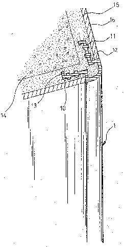
TITLE: A CORNER PROTECTIVE MEANS FOR WALLS, BEAMS COLUMNS ETC
ABSTRACT OF THE DISCLOSURE
A corner protective means for walls, beams, columns, etc. which
has adequately formed bevel angles, rib strips, and bent tails on
its two wings so that more powerful grip strength may be provided
by it when it is burried into a cement roughcast before the
cement is dried. With this corner protective means, a faster and
easier installation is available while smoother surface finish of
wall corner may be achieved easily.


Claims

Note: Claims are shown in the official language in which they were submitted.


I claim:
1. A corner protective means for walls, beams, columns etc
comprising a sectorial front and two integrally formed
wings; said wings extending outward from kwo edges of said
sectorial front whlle they first bend inward at said edges
of said sectorial fronk then bend outward to form an angle
about 30-40 degrees thereat permitting the wings to extend
in a direction substantially parallel to but slightly
inclined to a wall surface over which said corner
protective means is installed: said wings also having a
plurality of rib strips, formed on their both sides and an
inward bent tail formed at their free ends each.

Description

Note: Descriptions are shown in the official language in which they were submitted.


6~ 7 ~
TITLE: A CORNER PROTECTIVE MEANS FOR W~LLS, BEAMS, COLUMNS ETC.
_________ _____________________________________________________ .
Background of the Invention
_________________________._
In common construction of civil engineering, a lot of time is
wasted in stuccoing and strengthening projected corners of walls,
beams, columns, etc. Due to lack of proper corner protective
means, defects such as insufficient strength of corner, inferior
appearance, etc. also exists when the construction is
completed. Although there are other commercially available
simple corner protective means, most of them are inconvenient in
installation, inferior quality, low performance, and becoming
loose easily.
Therefore, it is tried by the applicant to develop a corner
protective means for walls, beams, columns, etc. Which may
eliminate the drawbacks existing in the prior art.
Summary of Invention
___.________________
It is a primary object of the present invention to provlde a
corner protective means which has a generally sec'corial front and
two wings extending outward from two edges of the sectorial front
to form a generally right angle, and may be insert into the
1 --
.
... . - ~ , '
' ' `` , ' ' ' '.
'' '

6~
concrete before final finish of walls, beams, columns etc., so
that it may firmly grip the concrete structure with many rihs,
bent tails, and bevel angles formed on its two wings.
The structure, functions, and other advantages o~ the present
invention may be readily understood by referring to the following
description and accompanying drawings in which:-
BRIEF DESCRIPTION OF THE DRAWLNGS
_________________ _______________
Fig.1 is a three-dimensional perspective of the
invention; and
Fig.2 illustrates a corner protective means of
the invention having been installed to
join with the concrete wall corner.
DETAILED DESCRIPTION OF PR~FERRED EMBODIMENT
____________________~__________________ ____
Please refer to~Fig.1. The corner protective means 1 of the
invention generally has a sectorial front and two wings 10
extending outward from two edges of the sectorial front. The
wings 10 are generally symmetrically formed, so, description of
one wing shall represent two wings in the specification. The
;

wing 10 firstly bends inward at an edge of the sectorial front,
then bends outward to form an angle about 30 or 40 degrees so
that the whole sectorial portion of the corner protective means 1
looks like a dove tail~ Furthermore, on both sides of the wing
10, a plurality of rib strips 11 are formed to increase the
contact area of the wing 10 with concrete structure and thereby
strengthens the holding of wing 10 by the concrete~
A bent tail 13 is formed at the open end of the wing 10 to
reinforce the grip capability of the wing 10. Please further
refer to Fig.2, in which a corner protective means of the present
invention having been installed and insert on a wall corner is
illustrated. From this figure, a powerful joining strength
provided by dovetail-shaped structure, xib strips 11, and bent
tails 13 of the corner protective means 1 can be fully
undsrstood.
During construction, please refer to Fig.2 concrete walls,
beams, columns, and their projected corners 14 formed by grouting
usually have a surface which needs a first time cement coating to
form a layer of roughcast 15. During the process of coating this
roughc~st 15, the corner protective means 1 of the invention is
positioned over the projected corner 14 in a manner that the
wings 10 are burried into the roughcast 15 before the same is
dried. ~hen the roughcast 15 is dried~ the the corner protective
means 1 shall be firmly inserted thereon. ~hen, a fine finish 16
'.' '' ~

formed by a second time cement coating shall provide a smooth
wall surface which is flush with the e~ges of the sectorial front
of the Corner protective means 1.
It is to`be understood that the form of the invention shown and
disclosed is to be taken as a preferred embodiment of the
invention and that various changes in the shape, size and
arrangement of parts may be resorted to without departirlg from
the spirit of the invention or the scope of the following
claims.

Representative Drawing
A single figure which represents the drawing illustrating the invention.
Administrative Status

2024-08-01:As part of the Next Generation Patents (NGP) transition, the Canadian Patents Database (CPD) now contains a more detailed Event History, which replicates the Event Log of our new back-office solution.

Please note that "Inactive:" events refers to events no longer in use in our new back-office solution.

For a clearer understanding of the status of the application/patent presented on this page, the site Disclaimer , as well as the definitions for Patent , Event History , Maintenance Fee  and Payment History  should be consulted.

Event History

Description Date
Time Limit for Reversal Expired 1995-05-01
Application Not Reinstated by Deadline 1995-05-01
Deemed Abandoned - Failure to Respond to Maintenance Fee Notice 1994-11-01
Inactive: Adhoc Request Documented 1994-11-01
Application Published (Open to Public Inspection) 1991-12-22
Request for Examination Requirements Determined Compliant 1990-12-06
All Requirements for Examination Determined Compliant 1990-12-06

Abandonment History

Abandonment Date Reason Reinstatement Date
1994-11-01
Owners on Record

Note: Records showing the ownership history in alphabetical order.

Current Owners on Record
MU-LONG CHIANG
Past Owners on Record
None
Past Owners that do not appear in the "Owners on Record" listing will appear in other documentation within the application.
Documents

To view selected files, please enter reCAPTCHA code :


To view images, click a link in the Document Description column (Temporarily unavailable). To download the documents, select one or more checkboxes in the first column and then click the "Download Selected in PDF format (Zip Archive)" or the "Download Selected as Single PDF" button.

List of published and non-published patent-specific documents on the CPD .

If you have any difficulty accessing content, you can call the Client Service Centre at 1-866-997-1936 or send them an e-mail at CIPO Client Service Centre.

({010=All Documents, 020=As Filed, 030=As Open to Public Inspection, 040=At Issuance, 050=Examination, 060=Incoming Correspondence, 070=Miscellaneous, 080=Outgoing Correspondence, 090=Payment})


Document
Description 
Date
(yyyy-mm-dd) 
Number of pages   Size of Image (KB) 
Claims 1991-12-21 1 18
Abstract 1991-12-21 1 16
Drawings 1991-12-21 2 47
Descriptions 1991-12-21 4 98
Representative drawing 1998-07-23 1 17
Fees 1994-01-06 1 27
Fees 1994-01-06 1 19
Fees 1992-10-28 1 20
Courtesy - Office Letter 1991-04-23 1 22
PCT Correspondence 1990-12-05 1 31
Examiner Requisition 1992-05-25 1 51
Prosecution correspondence 1992-11-09 3 117
Examiner Requisition 1994-01-20 2 65