Language selection

Search

Patent 2029335 Summary

Third-party information liability

Some of the information on this Web page has been provided by external sources. The Government of Canada is not responsible for the accuracy, reliability or currency of the information supplied by external sources. Users wishing to rely upon this information should consult directly with the source of the information. Content provided by external sources is not subject to official languages, privacy and accessibility requirements.

Claims and Abstract availability

Any discrepancies in the text and image of the Claims and Abstract are due to differing posting times. Text of the Claims and Abstract are posted:

  • At the time the application is open to public inspection;
  • At the time of issue of the patent (grant).
(12) Patent Application: (11) CA 2029335
(54) English Title: COUPLER DRAFT KEY PULLER
(54) French Title: EXTRACTEUR PERMETTANT DE RETIRER LA CLAVETTE DE L'APPAREIL DE TRACTION D'UN ATTELAGE DE WAGONS
Status: Deemed Abandoned and Beyond the Period of Reinstatement - Pending Response to Notice of Disregarded Communication
Bibliographic Data
Abstracts

English Abstract


ABSTRACT OF THE DISCLOSURE
Removing the draft key from a so-called E-type
railway car coupler can be a difficult job. A relatively
simple tool for removing a key of the type including a flanged
head includes a pair of parallel hydraulic cylinders, a yoke
interconnecting one end of the cylinders, piston rods
extending out of the other end of the cylinders, a sleeve in
the yoke parallel to the cylinders, an elongated shaft for
removable mounting in the sleeve, a latch for retaining the
shaft in the sleeve, and a socket in the outer free end of the
shaft for receiving the head of the key, whereby with the
shaft in the sleeve and connected to a key, extension of the
piston rods against the coupler pocket pushes the cylinders,
and consequently the sleeve and shaft outwardly to pull the
key from the coupler.


Claims

Note: Claims are shown in the official language in which they were submitted.

THE EMBODIMENTS OF THE INVENTION IN WHICH AN
EXCLUSIVE PROPERTY OR PRIVILEGE IS CLAIMED ARE DEFINED AS
FOLLOWS:
1. A device for removing a draft key of the type
including a shank and a head from a railway car coupler
comprising a pair of fluid actuated cylinder means; yoke means
interconnecting one end of said cylinder means for maintaining
the cylinder means in permanent, parallel spaced apart
relationship; piston rod means extending outwardly from the
other end of said cylinder means; sleeve means in said yoke
means; elongated shaft means for removable mounting in said
sleeve means; latch means for retaining said shaft means in
said sleeve means; and socket means in the outer free end of
said shaft means for receiving the head of a key, whereby,
with the shaft means in said sleeve means and connected to a
key, extension of the piston rod means against the coupler
causes outward movement of said cylinder means, sleeve means
and shaft means to pull the key from the coupler.
2. A device according to claim 1, wherein said
latch means includes a first opening in said shaft means; a
second opening in said sleeve means; and pin means for
insertion into said first and second openings.
3. A device according to claim 1, including stop
means on said socket means for limiting movement of a key
into said socket means.
4. A device according to claim 1, wherein said yoke
means includes a plate extending between said one end of the

cylinder means; and said sleeve means includes a square cross
section tube located centrally in said plate between the
cylinder means.
5. A device for removing a draft key of the type
including a shank and a head from a railway car coupler
comprising a pair of tubes; each having one closed end and one
open end; a pair of fluid actuated cylinders carried by said
tube means; a yoke interconnecting the closed ends of said
tubes for maintaining the cylinders in permanent, parallel,
spaced apart relationship, said yoke including a pair of
plates connected to each tube; a piston rod extending
outwardly from the other end of each cylinder; a square cross
section sleeve in said yoke between and parallel to said tubes
and cylinders; an elongated shaft for removable mounting in
the sleeve, a latch for retaining the shaft in the sleeve so
that the shaft extends between the piston rods; and a socket
in the outer free end of the shaft for receiving the head of a
key, whereby, with the shaft in said sleeve and connected to a
key, extension of the piston rods against the coupler causes
outward movement of the tubes, the cylinders, the sleeve and
the shaft to pull the key from the coupler.

Description

Note: Descriptions are shown in the official language in which they were submitted.


This invention relates to a pulling device, and in
particular to a device for removing a key from a railway car
coupler.
The removal of so-called E-type coupler draft keys
used on railway cars is very difficult, usually involving the
use of one key for driving a second key out of the latched
position. The result is often that the first key becomes
lodged and is difficult to remove. A search for a solution to
the above problem led to the present invention, the object of
which is to provide a relatively simple device for removing a
coupler draft key from a railway car coupler which is easy to
connect to the key.
Accordingly, the present invention relates to a
device for removing a draft key of the type including a shank
and a head from a railway car coupler comprising a pair of
fluid actuated cylinder means; yoke means interconnecting one
end of said cylinder means for maintaining the cylinder means
in permanent, parallel, spaced àpart relationship; piston rod
means extending outwardly from the other end of said cylinder
~0 means; sleeve means in said yoke means; elongated shaft means
for removable mounting in said sleeve means; latch means for
retaining said shaft means in said sleeve means; and socket
means in the outer free end of said shaft means for receiving
the head of a key, whereby, with the shaft means in said
sleeve means and connected to a key, extension of the piston
rod means against the coupler causes outward movement of said
, . . .
. .
'' . ' ' `

s~
cylinder means, sleeve means and shaft means to pull the key
from the coupler.
Fluid actuated cylinders previously have been used
in pulling devices. Examples of such devices are described in
U.S. Patents Nos. 2,452,457, issued to G. W. Gary et al on
October 26, 1948; 2,570,914, issued to C. N. Buck on October
9, 1951; 2,735,649, issued to S. A. Swallert on February 21,
1956; 2,874,933, issued to J. E. Feucht on February 24, 1959,
and 3, 066, 913, issued to ~. E. Leeson on December 4, 1962.
To applicant's knowledge, the above listed patents represent
the most relevant prior art. While some of the patented
devices have features in common with the invention described
herein, none of them offers the elegantly simple solution to
the problem solved by the present invention.
The invention will be described in greater detail
with reference to the accompanying drawings, which illustrate
a preferred embodiment of the present invention, and wherein:
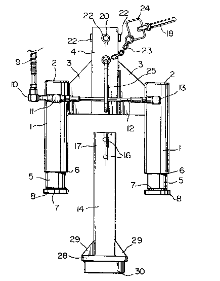
Figure 1 is an exploded, plan view of a pulling
device in accordance with the present invention;
Figure 2 is a perspective view of a shaft used in
the device of Fig. l;
Figure 3 is a schematic, perspective view of a
railway car coupler with the shaft of Fig. 2 connected
thereto; and
Figure 4 is a perspective view of the device of
Fig.l during a draft key removal operation.
''"'"'`'"`'''"`''''' '' ' ~
.

With reference to Fig. 1, the pulling device of the
present invention includes a pair of sleeves or tubes 1 each
having one closed end 2. The closed ends 2 of the tubes 1
are interconnected by generally triangular plates 3 which are
welded to the tube, and to an elongated, square cross section
sleeve 4. Plates 3 are provided on the top and bottom of the
tubes 2 and the sleeve 4, i.e. top and bottom plates 3 are
provided on both sides of the sleeve 4. The plates 3 and the
sleeve 4 define a yoke between the closed ends 2 of the tubes
1, with the sleeve 4 parallel to and one-half the distance
between the tubes 1. A hydraulic cylinder 5 is mounted in
each tube 1, extending out of the open end 6 thereof. A
piston rod or plunger 7 extends out of each cylinder 5. A
disc or saddle 8 is mounted on the outer end of the rod 7 for
defining a large bearing surface. Hydraulic fluid is fed into
and discharged from the cylinders 5 via a tube 9, an elbow 10,
a T-coupler 11, a tube 12 and an elbow 13.
The sleeve 4 which extends beyond the closed ends 2
of the tubes 1 is intended to receive a square cross section
shaft 14. For such purpose a pair of holes 16 extend through
the shaft 14 near one end 17 thereof for receiving a pin 18.
A washer 19 is mounted on the pin near the top end thereof for
limiting movement of the pin into aligned holes 20 (one shown)
in the top and bottom of the sleeve 4 when the sleeve holes 20
are aligned with one of the holes 16. A pair of holes with
short sleeves 22 extending outwardly therefrom are also
`~

~02~3~
provided in the sides of the sleeve 4, so that the shaft can
be rotated 90 and still slid into and connected to the sleeve
4. A chain 23 is connected to a 1QP 24 in the outer end of
the pin 18 for connecting the latter to a generally C-shaped
handle 25 on the front centre of the sleeve 4. Thus, one end
of the pin 18 is permanently connected to the handle 25, and
the other end thereof defines a portion of a latch for
releasably engaging the shaft 14.
A square plate 28 is mounted on the outer end of
the shaft 14 with reinforcing gussets 29 extending from the
corners thereof to the corners of the shaft 14. The plate 28
defines the inner end of a C-shaped socket 30 for receiving
the flanged outer end (not shown) of a coupler key 31 (Figs. 3
and 4). A plate 32 (Fig. 2) is provided on one end of the
socket 30 for limiting movement of the key into the socket.
In use, with the shaft 14 separated from the
remalnder of the device, the socket 30 is placed on the outer
free end of a key 31 (Fig. 3). The sleeve 4 is slid onto the
shaft 14 until one set of holes 16 and 20 are aligned. The
pin 18 is inserted into the aligned holes to couple the shaft
14 to the sleeve 4. Hydraulic fluid is introduced into the
cylinders 5 to extend the piston rods 7. Actually the rods 7
remain stationary in contact with the railway car coupler 34
(Fig. 3), while the cylinders 5 and the sleeve 4 move
outwardly. Because, the key 31, the shaft 14 and the sleeve 4

20293~
are interconnected, the key 31 moves outwardly with the shaft
and the sleeve.
Thus, the key pulling operation is quick and easy.
The device of the present invention is simple, lightweight and
inexpensive to manufacture. The use of easily separated and
re-connected elements facilitates the key pulling operation.
Moreover,it is not necessary to manipulate a heavy piece of
equipment into position.

Representative Drawing
A single figure which represents the drawing illustrating the invention.
Administrative Status

2024-08-01:As part of the Next Generation Patents (NGP) transition, the Canadian Patents Database (CPD) now contains a more detailed Event History, which replicates the Event Log of our new back-office solution.

Please note that "Inactive:" events refers to events no longer in use in our new back-office solution.

For a clearer understanding of the status of the application/patent presented on this page, the site Disclaimer , as well as the definitions for Patent , Event History , Maintenance Fee  and Payment History  should be consulted.

Event History

Description Date
Revocation of Agent Requirements Determined Compliant 2020-09-01
Inactive: IPC from MCD 2006-03-11
Inactive: Inventor deleted 2001-01-24
Application Not Reinstated by Deadline 1995-05-06
Time Limit for Reversal Expired 1995-05-06
Inactive: Adhoc Request Documented 1994-11-07
Deemed Abandoned - Failure to Respond to Maintenance Fee Notice 1994-11-07
Application Published (Open to Public Inspection) 1992-05-06

Abandonment History

Abandonment Date Reason Reinstatement Date
1994-11-07
Owners on Record

Note: Records showing the ownership history in alphabetical order.

Current Owners on Record
DAVID W. REESOR
Past Owners on Record
None
Past Owners that do not appear in the "Owners on Record" listing will appear in other documentation within the application.
Documents

To view selected files, please enter reCAPTCHA code :


To view images, click a link in the Document Description column. To download the documents, select one or more checkboxes in the first column and then click the "Download Selected in PDF format (Zip Archive)" or the "Download Selected as Single PDF" button.

List of published and non-published patent-specific documents on the CPD .

If you have any difficulty accessing content, you can call the Client Service Centre at 1-866-997-1936 or send them an e-mail at CIPO Client Service Centre.


Document
Description 
Date
(yyyy-mm-dd) 
Number of pages   Size of Image (KB) 
Claims 1992-05-06 2 62
Abstract 1992-05-06 1 19
Cover Page 1992-05-06 1 15
Drawings 1992-05-06 2 42
Descriptions 1992-05-06 5 142
Representative drawing 1999-06-30 1 20
Fees 1993-11-04 1 31
Fees 1992-11-03 1 25