Note: Descriptions are shown in the official language in which they were submitted.
2029391
1 ELECTRONIC GAP SENSOR AND METHO~
The U.S. Government has a paid-up license in this
invention and the right in limited circumstances to
require the patent owner to license others on
reasonable terms as provided for by the terms of
contract No. DE-FC07-88ID12712 awarded by the U.S.
Department of Energy.
TECHNICAL FIELD
This invention relates to devices for monitoring
the distance between two surfaces, and, more
particularly, to a device having a protruding member
which completes an electrical circuit when in
contact with another surface. This invention ha~
particular application for use in precisely
controlling the distance between a casting nozzle and
a casting wheel.
BACKGROUND ART
Generally, casting is the process by which molten
material is formed into solid shapes. A known method
for casting materials has involved the use of rolling
cylinders to compress slabs of cast material to a
desired thickness. However, this process is very
energy intensive and costly.
An alternative casting method for producing a
strip of material of a desired thickness, known as
strip casting, incorporates a rotating wheel, drum,
belt or other substrate. The rotating substrate is
~'
''~
-
2029391
1 placed in close proximity to a casting nozzle from
which molten material flows. The molten material is
deposited on the rotating substrate where it cools,
solidifies or "freezes", and is subsequently removed
for further processing.
However, when the molten material is initially
introduced through the casting nozzle and onto the
casting wheel, heat is exchanged from the high
temperature molten material to the lower temperature
casting nozzle and casting wheel. This transfer of
heat energy to the casting nozzle and the casting
wheel causes them to expand, often in an
unpredictable and non-uniform manner. As a result of
this expansion, the distance between the adjacent
surfaces of the casting wheel and the casting nozzle
is often reduced.
Until the temperatures of the casting nozzle and
the casting wheel reach a steady state, at which time
further expansion of the casting nozzle and the
casting wheel is minimized, the gap between them will
not be a uniform or constant distance. In at least
the case of planar flow casting, an example of which
is illustrated in U.S. Patent 4,771,820, the gap
between the casting nozzle and the casting substrate
can affect the thickness of the cast material, which
is generally crucial to the quality of the cast
material. If the cast material does not have the
desired thickness, it may either be scrapped or
mechanically reformed, both of which are expensive,
time consuming, and inefficient.
The inability to control and maintain a desired
distance or gap between the casting nozzle and the
3 2~29~91 62804-l026
castlng wheel can also cause a varlety of other problems durln~
casting. For exarnple, lf the dlstance between the castlng nozzle
and the actlng wheel becomes too large, the molten materlal can
flow along the face of the castlng nozzle rather than onto the
castlng wheel. Materlal whlch ls not deposlted onto the castlng
wheel wlll inherently begln to cool as lt flows along the nozzle,
and can thereby lnterfere wlth the efflclent operatlon of the
machlnery and compromlse the quallty and unlformlty of the
resultant cast product. Conversely, lf a mlnlmum gap between the
casting nozzle and the castlng wheel ls not malntalned, contact
may occur between them whlch can result ln severe damage to both
the nozzle and the wheel. Such a sltuatlon obvlously lnterferes
wlth the safety and efflclency of the castlng process.
In partlcular, when steel and other hlgh temperature
materlals are strlp cast, the relatlve expanslons of the castlng
nozzle and castlng wheel are vlrtually lrnpossible to avold. Slnce
lt ls not generally economlcal to pre-heat a castlng nozzle and a
castlng wheel to thelr steady state temperatures, a variety of
methods have been used to measure and malntaln the dlstance
between a castlng nozzle and a casting wheel.
-
202Q391
1 Some of the known methods include: product
measurement, wherein the thickness of the cast
material is measured downstream dynamically and the
gap between the casting nozzle and casting wheel
thereafter adjusted to compensate for measured
thickness variations; and laser gap sensing, wherein
a laser beam is utilized to measure the gap between
the casting nozzle and the casting wheel.
All of the known methods and equipment have
serious drawbacks, however. Indirect or downstream
control of the distance between the casting nozzle
and casting wheel from the downstream measurement of
the resulting thickness of the cast material is
complicated by the possible influence of other
casting variables, such as casting speed, cooling,
and composition, on the measured cast thickness.
Moreover, downstream measurements are by definition
Uafter the fact" quality controls, and undesirable
rework or scrapping of the measured cast product is
not avoided. Laser methods, on the other hand, are
expensive and complicated to perform, especially for
casts of wide strips of very hot alloys such as
steel. In addition, lasers require a straight line
of sight between the laser source and the photodiodes
or similar laser detectors, through which the laser
beam may travel. Unencumbered straight lines of sight
are often not available between the expanding casting
nozzle and substrate and, at least, difficult to
provide. Moreover, the presence of smoke, heat, dust
and other gases and particles produced during casting
may interfere with (e.g. diffract) and restrict the
passage of a laser light through the gap. Examples
of devices of these types are disclosed in U.S.
Patent 2,383,310 and U.S. Patent 4,399,861.
202g391
62804-1026
Consequentlyr heretofore, there has not been avallable a
simple, reliable and economical device for malntaining a
predetermined gap between two surfaces. In particular, such a
device has not been avallable for use ln hostile environments such
as strip casting.
DISCLOSURE OF THE INVENTION
Accordingly, the present invention provides an apparatus
for monitoring the gap between a casting nozzle and a casting
surface of a substrate for casting molten material, wherein the
molten materlal is provided through the casting nozzle for casting
onto the castlng surface of the substrate for solidlfication and
at least a portion of said casting surface ls electrically
conductlve, sald apparatus comprlslng:
(a) a senslng element attached to sald castlng nozzle
ad~acent sald gap and ln proximity to and aligned with sald
electrically conductive portion of the casting surface of said
substrate, said sensing element having a sensing tip extending
outwardly a predetermined dlstance from sald nozzle towards sald
castlng surface;
(b) a source of electrical voltage arranged such that upon
effective contact of sald senslng tip with sald casting surface,
an electrlcal current is established in said sensing element; and
(c) where~n the presence of said electrlcal current can
accurately indicate when the gap between said nozzle and said
casting surface reaches a predetermined minimum distance.
From another aspect, the lnvention provldes a method for
monltorlng the gap between a castlng nozzle and a castlng surface
2029391 62804 l026
of a substrate for continuous castlng of molten materlal, at least
a portlon of sald castlng surface belng electrically conductlve,
sald method comprlslng the followlng steps:
(a) provldlng a castlng nozzle having a senslng element
attached to sald castlng nozzle ad~acent sald gap and ln proxlmlty
to and aligned with sald electrlcally conductlve portlon of the
castlng surface of sald substrate, said sensing element havlng a
senslng tlp extendlng outwardly a predetermlned dlstance from sald
nozzle towards sald castlng surface, and having a source of
electrlcal voltage arranged such that upon effectlve contact of
sald senslng tlp wlth sald castlng surface, an electrlcal current
ls establlshed ln sald senslng element, whereln establlshment of
sald electrlcal current can accurately lndlcate when the gap
between sald nozzle and sald castlng surface reaches a
predetermlned mlnlmum dlstance;
~ b) locatlng sald nozzle and sald castlng surface ln
proxlmlty wlth one another such that sald senslng element
lndlcates contact wlth sald casting surface;
(c) ad~usting the relatlve posltlons of sald nozzle and sald
castlng surface to provlde a predetermined gap therebetween;
(d~ providing molten materlal to said nozzle for castlng onto
said casting surface; and
~ e) monitorlng the gap between sald nozzle and sald casting
surface during castlng procedures, whereby contact of sald senslng
tlp wlth sald castlng surface establlshes said electrlcal current.
Preferably the devlce for contlnually and accurately
monltorlng the dlstance between a castlng nozzle and a castlng
substrate wlll rellably operate ln the hostlle envlronment and
2029391
6a 62804-1026
extreme temperatures assoclated wlth castlng an electronlc gap
sensor determlnes the dlstance between a casting nozzle and a
castlng wheel by the completlon of an electrlcal clrcult between
the castlng nozzle and the castlng wheel to lndlcate predetermlned
gap wldths, and operates ln con~unctlon wlth means for dynamlcally
controlllng the relatlve dlstance between the castlng nozzle and
the castlng wheel.
BRIEF DESCRIPTION OF THE DRAWINGS
The followlng drawlngs incorporated ln and formlng a
part of the speclflcatlon illustrate several aspects of the
present lnventlon and together wlth the descrlptlon serve to
explaln the prlnclples of the lnventlon. In the drawings:
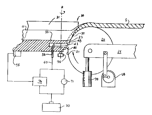
FIG. 1 is a partial perspective vlew of a castlng station in
whlch a preferred embodlment of the
7 2029391
1 present invention is illustrated;
FIG. 2 is a partial cross-sectional schematic
view of the casting station of FIG. l;
FIG. 3 is an enlarged cross-sectional view of the
electronic gap sensor of FIGS. 1 and 2;
FIG. 4 is a partial perspective view of a casting
nozzle incorporating an alternative preferred
embodiment of the present invention; and
FIG. 5 is an electrical schematic illustration of
a simple sensing circuit which can be used in
accordance with the present invention.
DETAILED DESCRIPTION OF THE INV~ llQN
Referring now to the drawings in detail, wherein
like numerals indicate corresponding elements
throughout the views, FIG. 1 illustrates a partial
perspective view of a casting station 15 located on a
longitudinal bed 10. Casting station 15 will
preferably comprise casting nozzle 30 and casting
wheel or substrate 20. In a preferred embodiment,
casting wheel 20 is rotatably mounted on arms 25 such
that casting wheel 20 may be rotated by any means
about an axis substantially parallel to the upper
surface of longitudinal bed 10.
Arms 25 are rotatably mounted at one end to
supporting block 24 such that arms 25 may be rotated
in an arc having an axis substantially parallel to
axis A of casting wheel 20. Supporting block 24 is
securely attached to table 91 and may comprise a
motor (not shown) for rotating wheel 20 by means such
8 2029391
1 as drive linkage 26. Drive linkage 26 may comprise
any coupling, belt, chain, rod or the like for
rotating casting wheel 20. Alternatively, casting
wheel 20 may be rotated by any means, such as a
motor, provided along axis A of casting wheel 20.
Casting wheel 20 is preferably generally
cylindrical in shape and rotatable about a central
axis A. Casting wheel 20 is preferably rotated at
between about 50-5000 feet/min. (15-1500 meters/min.)
surface speed for typical strip or foil casting.
Obviously such surface speed will be a function of
the rotational speed of casting wheel 20 and diameter
D thereof. However, as will become apparent herein,
the present invention is not dependent upon the speed
of the casting wheel.
It should be understood that configurations for
substrate 20 other than cylindrical conformations may
be employed. For example, a casting wheel with a
smooth frustoconical outer peripheral surface or a
belt-like continuous moving substrate (not shown)
might equally be utilized. Regardless of the
configuration of the wheel, drum, or other substrate
employed, the casting surface should be at least as
wide as the strip of material to be cast.
In a preferred embodiment, casting wheel 20
comprises a water cooled copper alloy wheel. Copper
and copper alloys are preferably used for their high
thermal and electric conductivity and favorable wear
resistance. However, within the spirit of the
present invention, steel, brass, aluminum, aluminum
alloys, and other materials may equally be utilized.
As will be seen, it is important that at least a
9 2029391
1 portion of the surface of the substrate or wheel
(e.g. 30) be capable of conducting electricity to
complete an electrical circuit upon contact with a
sensing element.
In the operation of strip casting station 15 such
as shown in FIG. 1, the surface 21 of casting wheel
preferably must also be able to absorb and/or
dissipate heat generated from contact with molten
material in order to facilitate cooling of the cast
material. As mentioned, in a preferred arrangement
heat is removed from casting wheel 20 by circulating
a sufficient quantity of water to the interior and/or
exterior surfaces of casting wheel 20. Refrigeration
techniques or similar cooling arrangements may also
be employed to cool casting wheel 20. The use of
cooling channels within a casting substrate is known
in the industry and will not be further described
herein. Likewise, casting wheel 20 may be cooled
with the use of a medium other than water, including
other cooling fluids such as freon, coolants, and the
like. Water is chosen for its low cost, ready
availability, and relative general safety.
During casting procedures, casting nozzle 30 is
spaced in close proximity to surface 21 of casting
wheel 20. Casting nozzle 30 is constructed of any
material suitable for casting such as silica brick or
the like. In general, for obvious reasons, such
materials preferably have a melting point higher than
that of the molten material to be introduced into the
casting nozzle. Casting nozzle 30 may be of any
suitable shape such that casting nozzle face 32 of
casting nozzle 30 may be brought into close proximity
with surface 21 of casting wheel 20 during casting.
lo 2~29391
1 It is understood that casting nozzle 30 should be
sufficiently warm before molten material is
introduced therein so that the molten material does
not generally solidify within channel 31 but instead
flows onto substrate 20.
Casting nozzle face 32 preferably protrudes from
the surface of casting nozzle 30 adjacent surface 21
so as to limit the overall area of nozzle 30 which
will be in close proximity with surface 21 during
casting operations. Due to the generally higher
steady state temperature of casting nozzle 30
relative to the preferably cooler casting substrate
20, limiting the area of nozzle 30 in close proximity
with surface 21 helps to minimize the transfer of
heat energy from nozzle 30 to casting substrate 20.
In addition, casting nozzle face 32 preferably has a
conformation corresponding to and approximately the
same radius of curvature as adjacent surface 21 of
casting wheel 20, so that a predetermined distance
can be substantially uniformly maintained between
casting nozzle face 32 and the adjacent surface 21 of
casting wheel 20 over substantially the entirety of
these opposed surfaces.
As illustrated in Figures 1-3, within casting
nozzle 30 is preferably provided a channel 31 for
directing the flow of molten material onto casting
wheel 20. Channel 31 may be of any suitable shape to
facilitate the flow of molten material towards
casting wheel 20. As shown, bed 33 provides the
lower portion of channel 31.
As best seen in FIG. 2, when molten material 11
is introduced into casting nozzle 30, it flows within
ll 2029391
1 channel 31, along bed 33, and onto casting wheel 20.
A gap 23 is preferably maintained between casting
wheel 20 and casting nozzle 30 so that castinq wheel
20 may freely rotate and the desired thickness of
material may be cast. Gap 23 is the distance between
the closest opposed points on casting nozzle face 32
and surface 21 of casting wheel 20. During typical
strip casting, gaps in a range of between about .005"
(.125 mm) and about .030" (.75 mm) are usually
desired. However, the invention disclosed herein is
not theoretically limited by the dimension of gap 23
and may be generally utilized within the practical
limits of molten material 11 flowinq from casting
nozzle 30 to casting wheel 20. As discussed herein,
the present invention may be utilized when molten
material 11 is cast at temperatures associated with
red heat, typically over 1000F (over 604C).
Due to the flow, viscosity and inherent surface
tension of molten material 11, the molten material
effectively generally flows across gap 23 and onto
casting wheel 20 as generally illustrated in FIG. 2.
During casting, surface 21 of casting wheel 20
adjacent to bed 33 is rotating generally upwardly
relative to bed 33 as it passes nozzle face 32 so
that molten material 11 is deposited on casting wheel
20 and carried towards the top of the casting wheel.
During casting operations, it is preferable to
deposit molten material 11 on the upper quadrant of
surface 21 adjacent to casting nozzle 30.
Referring now to FIG. 2, due to the cooling
characteristics of casting wheel 20, molten material
11 generally begins solidification after initial
contact with surface 21 of casting wheel 20. As
-
2029391
1 shown with cross-hatching, as molten material 11
solidifies and cools on surface 21, molten material
in contact with the solidified material likewise
generally cools and solidifies on the previously
deposited material, generally increasing the
thickness of solidified material on surface 21
downstream. During typical drag flow casting, the
resulting thickness of cast material produced is
principally determined by the speed and temperature
of surface 21 and the length of the arc over which
molten material 11 contacts surface 21 and the
solidified material thereon. In addition, the
vertical sides of channel 31 adjacent to surface 21
may limit the transverse spreading (i.e. the lateral
outward spreading from the sides of channel 31) of
molten material 11 which has been deposited on
substrate 20 yet has not solidified prior to exiting
channel 31. Upon solidification, the cast material
is thereafter removed from the casting wheel, as
strip cast S.
In order to maintain gap 23 at a predetermined
distance, a preferred embodiment of electronic gap
sensor 40 of the subject invention is shown in
Figures 1-3. At least one (and preferably a
plurality of) gap sensor 40 will be provided to
continually monitor gap 23 during casting
procedures. Sensing element 60, which preferably
comprises an electrical wire, will be described in
greater detail below. As best seen in FIG. 3, sensor
40 preferably comprises a sensor body 41 and sensing
element 60 and is provided adjacent casting nozzle
face 32 such that the electrically conductive portion
of surface 21 will pass in front of sensor 40 when in
proximity. Sensor 40 is preferably secured to
13 2029391
1 casting nozzle 30 such as within a cavity 34. Cavity
34 is preferably located beneath bed 33 to
effectively space sensor 40 away from the flow of
molten material, and to minimize the potential for
direct contact with such molten material. It is also
understood that cavity 34 and sensor 40 should be
located sufficiently below bed 33 to avoid
compromising the integrity of bed 33 (in applications
where sensor 40 is actually mounted bodily within
nozzle 30) so that molten material may flow thereover
without damage to bed 33 or casting nozzle 30.
Sensor 40 can operate reliably when located within
about 0.5" (12.5 mm) of bed 33.
As mentioned, the present invention is
constructed to withstand the hostile conditions and
high temperatures associated with casting and may
encounter temperatures over 1000F (over 604C) due
to its proximity to molten material 11. Although the
electronic sensor of the present invention may be
mounted at a variety of positions on the exterior of
casting nozzIe 30 so long as the electrically
conductive portion of surface 21 of casting wheel 20
travels in front thereof, it is preferred that sensor
be located as close as practical to the region
where molten material is actually transferred from
casting nozzle 30 to casting substrate 20. It is
only by such proximate positioning that a true
determination of the actual casting gap can be
reliably achieved, and it is this close positioning
that gauging devices and methods heretofore available
have lacked and generally could not survive the
attendant environment. In the preferred embodiment
disclosed herein, sensor 40 is secured at least
partially within nozzle 30, as illustrated in FIGS.
1-3.
2029391
1 Cavity 34 is generally cylindrical in shape and
extends from casting nozzle face 32 inward into
casting nozzle 30. It should be noted that cavity 34
may be of any shape (e.g. cylindrical, square,
rectangular, etc.) appropriate for securing sensor
body 41 therein. As shown in FIG. 3, sensor body 41
is also preferably generally cylindrical in shape,
and is secured within cavity 34 such as by means of a
high temperature refractory adhesive 84.
A depression or recess 47 is provided about a
portion of sensor body 41 within casting nozzle 30.
Depression 47 preferably circumscribes the exterior
periphery of sensor body 41 and is preferably
utilized where adhesive 84 will not rigidly attach to
sensor body 41 or to augment the connection. When
the adhesive within depression 47 hardens to the
adjacent portion of cavity 34 in casting nozzle 30,
it may thereby function as a mechanical lock for more
0 rigidly securing sensor body 41 within cavity 34.
However, any other attachment and/or securing means
may be utilized for mounting sensor body 41 on nozzle
30.
One or more gap sensors 40 will be provided to
continually monitor gap 23 during casting
procedures. Sensor face 43, the distal end of sensor
body 41 most closely adjacent to casting wheel 20,
also preferably has a conformation corresponding to
and of approximately the same radius of curvature as
adjacent surface 21 of casting wheel 20. Where
-- sensor face 43 is not provided with such conformation
before installation of sensor body 41 within cavity
34, sensor face 43 may be appropriately dressed to
proper conformation (as discussed herein) by placing
2029391
1 an abrasive surface, such as emery paper, against the
adjacent surface 21 of casting wheel 20. When
surface 21 is brought into contact with sensor face
43, the abrasive surface will substantially conform
to the curvature of adjacent surface 21 and may
thereby be utilized to abrade sensor face 43 to the
curvature of adjacent surface 21.
A passageway 36 is provided in casting nozzle 30
which communicates with cavity 34. Passaqeway 36 is
also preferably generally cylindrical in shape;
however, passageway 36 may be of any appropriate
shape (e.g. cylindrical, square, rectangular, etc.)
for securing a conduit 56 therein. As shown in FIG.
3, conduit 56 is also preferably generally
cylindrical in shape, hollow, and secured within
passageway 36 such as by means of a high temperature
refractory adhesive. Any other attachment and/or
securing means may be utilized for attaching conduit
56 within passageway 36. Conduit 56 may be of any
appropriate shape such that a sensing element 60 may
pass therethrough.
In the event casting nozzle 30 is electrically
conductive, sensor body 41 and conduit 56 should
comprise nonconductive elements to shield sensing
element 60 from casting nozzle 30. In the event
casting nozzle 30 is not electrically conductive, any
suitable material may be used for those parts. As
will be further discussed herein, it is preferable
that sensor body 41 comprise a material with a low
coefficient of thermal expansion so that the length
of the portion (i.e. protrusion 48) of sensor body 41
extending outwardly from nozzle face 32 does not
significantly change as sensor body 41 is exposed to
16 2029~91
1 temperature variations. The portion of sensor body
41 extending from casting nozzle face 32 must also be
able to withstand the relatively hostile oxidation
conditions created by the flow of molten material
onto a cooler substrate. Sensor body 41 might
preferably be formed of a material such as boron
nitride for both conductive and nonconductive casting
nozzles due to its nonconductivity, low coefficient
of thermal expansion and superior resistance to
oxidation. Conduit 56 preferably comprises a ceramic
sheath although any appropriate material may be used.
In a preferred embodiment, sensing element 60 is
housed within conduit 56 and sensor body 41, as best
seen in FIG. 3. A longitudinal bore is preferably
provided along the axis L of sensor body 41, within
which sensing element 60 may be mounted. Sensing
element 60 is constructed of an electrically
conductive material, and preferably has a low
coefficient of thermal expansion so that the distance
which sensing tip 61 of sensing element 60 protrudes
from casting nozzle face 32 does not significantly
change as sensing element 60 is exposed to
temperature variations. Sensing element 60 should
also be able to withstand the oxidizing conditions
present in casting procedures in general, and should
be at least relatively resistant to wear as it may be
in physical contact with surface 21 of casting wheel
from time to time. In a preferred embodiment,
sensing element 60 comprises platinum or nichrome
wire, and is approximately .020" (.5 mm) in
diameter. Graphite, silver, nickel, or aluminum
materials can also be used in appropriate
applications. It should be noted that the exact
diameter of the wire is not critical to the operation
of the present invention.
-
17 2 ~29 391
1 Sensing element 60 should also be sufficiently
resilient such that it will resist permanent
deformation and resume its initial conformation after
removal of a deforming force. Sensing tip 61 should
corresponding resume a predetermined distance from
casting nozzle face 32 after removal of a deforming
force. The support and resilience of sensing element
60 may be preferably aided by surrounding sensor body
41 extending from nozzle face 32 to sensing tip 61.
Sensing tip 61 of sensing element 60 terminates
adjacent sensor face 43. As seen best in FIG. 3,
sensing tip 61 and sensor face 43 of sensor body 51
extend outwardly a predetermined distance beyond
casting nozzle face 32 towards surface 21 of casting
wheel 20. Where sensing element 60 protrudes from
nozzle face 32 in a direction substantially normal to
nozzle face 32 and surface 21, the predetermined
distance or length of protrusion 48 (i.e. that
portion of the sensor body 41 and sensing tip 61
extending beyond casting nozzle face 32) is
preferably equal to the desired width W of gap 23.
However, sensing element 60 may extend from nozzle
face 32 in a non-normal relationship as well. In
those cases, the normal distance between sensing tip
61 and nozzle face 32 can be readily computed and
accounted for using basic trigonometric algorithms.
In practice, the desired distance sensing tip 61
extends from nozzle face 32 can be readily achieved
during the shaping of sensor face 43, as discussed
herein. A standard depth gauge may be used to
monitor this distance as sensor face 43 is
progressively dressed. This dressing operation is
terminated when sensing tip 61 has a desired normal
distance.
18 2029391
1 The proximal end of sensing element 60 extends
from sensor body 41, and exits casting nozzle 30
through conduit 56. In a preferred embodiment,
conduit 56 includes a longitudinal bore wherein
sensing element 60 is mounted. The proximal end of
sensing element 60 is connected to a control 76 and
indicator 71 which are connected in parallel with
voltage source 70, such as shown in FIG. 2. Also
preferably connected to sensing element 60 is a
control 76, and an indicator 71 (e.g. a lamp, buzzer,
or the like) for registering the flow of current
through sensing element 60.
In order to prevent the flow of current from
voltage source 70 when sensing tip 61 is not in
contact with grounded casting wheel 20, sensing
element 60 must not be grounded. If casting nozzle
is not electrically conductive, the insulating
features of sensor body 41 and conduit 56 may be
essentially eliminated. The complete absence of
sensor body 41 around sensing tip 61 may, however,
permit sensing tip 61 to deflect and/or bend such
that protrusion 48 no longer equals the desired width
W of gap 23. The length of the protruding portion of
sensing element 60 could be calibrated based upon its
deflection from a line substantially normal to nozzle
face 32 and surface 21.
As shown in FIG. 2, control 76 is provided for
operation of the means (e.g. 90, 95 and 97) for
3 adjusting the relative position of casting nozzle
face 32 to the adjacent surface 21 of casting wheel
20. In one embodiment of the present invention,
operation of the adjustment means can be accomplished
manually by an operator responding appropriately to
lg 2029391
1 contact signals from indicator 71. When the
adjustment means is manually operated, indicator 71
is constructed to provide a signal perceptible by
human senses, preferably either visual or audible.
Accordingly, indicator 71 may be either a lamp or
buzzer. As shown in FIG. 2, indicator 71 is
connected to sensing element 60 such that the
establishment of current in sensing element 60 will
activate indicator 71. In a preferred embodiment,
indicator 71 fails to produce a response when sensing
tip 61 is not in contact with casting wheel 20.
However, within the scope of this invention, any
indicator arrangement can be used. For example,
indicator 71 may be constructed such that a response
(e.g. energization of a lamp or buzzer) is produced
when current is not maintained or established in
sensing element 60. It is thus understood that
indicator 71 may respond to the relative presence
(either the establishment or absence) of current in
sensing element 60.
In an alternative embodiment of the present
invention, control 76 comprises a computer and
control relays. When sufficient electrical current
is present in sensing element 60, a control relay
preferably transmits a signal to the computer which
thereafter makes appropriate adjustments to the
relative positions of casting nozzle 30 and casting
wheel 20.
When sensing tip 61 is in close proximity to
surface 21, electrical current may arc from sensing
tip 61 to surface 21. In such a case, the apparent
width of gap 23 will not generally equal the actual
distance sensing tip 61 protrudes from nozzle face
2029391
1 32. Since electrical arcing is generally
unpredictable and may occur over a variety of
distances, it is preferable that such arcing be
minimized. In the preferred embodiment illustrated
in FIG. 2, the current supplied by voltage source 70
is typically 24V DC when four sensors 40 are
utilized. It is preferred that sensing element 60 be
on the low voltage side of the current and that wheel
be at ground potential. As control 76 and
indicator 71 generally have a relatively high
electrical resistance (generally at least several
hundred ohms), the total electrical current which may
pass through sensing tip 61 is preferably small. The
upper limit on this current can be calculated,
assuming no resistance in sensing element 60, as
equal to the supply voltage divided by the effective
resistance of control 76 and indicator 71. As can be
understood, supplying a low voltage to the sensing
tip 61 reduces the possibility of arcing and
attributes to the general safety and precision of the
present invention. As used herein, relatively low
voltage shall be understood to connote voltage which
will produce an insignificant arc, preferably less
than 5 volts.
Control 76 may be preferably designed such that
the electrical potential of sensing tip 61 has a very
low value before any control action is initiated.
This reduces the possibility of premature movement of
either nozzle 30 and/or substrate 20 caused by arcing
from sensing tip 61 to surface 21 because the low
voltage necessary to actuate control 76 is
insufficient to sustain an arc. This low actuation
voltage may be set such it is present in sensing
element 60 only when sensing tip 61 is in physical
2029391
21
1 contact with surface 21.
As shown in FIG. 1, a sensor 40 is provided on
casting nozzle face 32 in close proximity to bed 33.
Based upon the presence or absence of sufficient
current in sensor element 60, casting nozzle 30 and
casting wheel 20 can be continually adjusted during
casting operations along essentially any plane or
about any axis in the X-Y-Z triordinate system
illustrated by a variety of mechanical means. Where
only one sensor 40 is utilized, first axis adjustment
means 90 is preferably provided to regulate the
relative position of nozzle face 32 and surface 21
along the X axis. Although a variety of adjustment
means may be utilized in conjunction with a single
sensor 40, the contact of a sensing element 60 at a
single location generally limits the information
which may be obtained regarding the width W of gap 23
along other portions of nozzle face 23. Pivot point
96 and track 95 are provided to rotate nozzle 30
about point 96 to enable adjustments along the X and
Y axes, while adjustment means 97 with arms 25 permit
adjustment of wheel 20 along the X and Z axes.
When molten material is introduced through
casting nozzle 30 and onto casting wheel 20, those
areas of nozzle 30 and wheel 20 in closest proximity
or contact with the molten material generally
experience greater thermal expansion than the rest of
nozzle 30 and substrate 20, respectively. In
practice, the portions of nozzle 30 and substrate 20
generally located along the flow of the molten
material expand the greatest such that the adjacent
central portions of nozzle 30 and wheel 20 generally
expand toward each other. During casting procedures,
, 2029391
1 the width W of gap 23 between surface 21 and the
centerpoint of bed 33 adjacent surface 21 is
generally less than the width of a gap between
surface 21 and a point located on the periphery of
casting nozzle 30. Placement of sensor 40 near the
centerpoint of bed 33 adjacent to surface 21
generally can help to ensure that casting nozzle 30
does not contact casting wheel 20.
In another embodiment of the present invention,
as illustrated in FIG. 4, more than one electronic
gap sensor (e.g. 140) may be used with in conjunction
with a casting nozzle (e.g. 130). Such an
arrangement may be preferred for longer casting
operations, or when casting wider or thicker casts,
and/or where a plurality of adjustment means (e.g.
90, 95, and 97) are provided to maintain a
predetermined variable width gap between nozzle face
132 and the surface of a casting substrate (not
shown). In this alternative embodiment, electronic
gap sensors 140 are installed in the casting nozzle
130 along the lower surface of casting nozzle face
132. As also illustrated, electronic gap sensors
140a may be installed on casting nozzle face 132
above the lower sensors. The use of a plurality of
electronic gap sensors allows for the determination
of whether specific portions of casting nozzle face
132 are a predetermined distance from a casting
substrate (not shown) and can be utilized to maintain
a gap with certain predetermined widths between the
nozzle and the substrate.
Based upon the presence or absence of current in
registered by the one or more electronic gap sensors,
casting nozzle 30 can be continually dynamically
23 2029391
1 adjusted during casting operations with respect to
casting wheel 20 along a variety of orientation
planes or axes by a variety of mechanical means. As
shown in FIG. 1, casting wheel 20 is positioned on
table 91 which is provided for translation along the
X axis, such as on rails 92. Table 91 is connected
to first axis adjustment means 90 which, in a
preferred embodiment, comprises a hydraulic or
pneumatic piston for selectively positioning wheel 20
relative to casting nozzle 30. When surface 21 of
casting wheel 20 is in proximity with casting nozzle
face 32, table 91 encounters load means 93, which are
disposed beside rails 92.
As shown in FIG. 1, load means 93 may operate to
provide a resistance to the movement of table 91 by
adjustment means 90 towards casting nozzle 30 such
that any slack in the system may be minimized and
precise adjustments to the relative positions for
nozzle face 32 and surface 21 can be made.
Furthermore, in a preferred embodiment of the present
invention, first axis adjustment means 90 and load
means 93 are provided to maintain a constant force to
table 91 such that any elastic deformation of table
91 is held constant during its translation.
In this preferred arrangement, an adjustable stop
94 is provided for precisely translating table 91.
Where first adjustment means 90 provides a constant
force greater than that provided by load means 93,
table 91 is positioned into contact with adjustable
stop 94 during the translation of table 91.
Adjustable stop 94 may thereby precisely adjust the
relative position of nozzle 30 and substrate 20
without generally further elastic deformation of
24 2029391
table 91. Adjustable stop 94 preferably comprises
any precise adjustment means such as a hydraulic or
pneumatic piston, or ball screw arrangement.
Where it is desirable to further control gap 23,
second adjustment means 97 may be provided,
preferably comprising a lift 98 and a counterlift
99. Lift 98 is illustrated as comprising a hydraulic
piston to raise casting wheel 20 along the Z axis and
to provide a preloaded resistance to the downward
movement of casting wheel 20 by counterlift 99 such
that slack in second adjustment means 97 may be
minimized.. Counterlift 99 comprises a motorized cam
or any other precise adjustment device.
As described herein and illustrated in FIG. 2,
the molten material 11 furthest away from bed 33
solidifies on previously deposited and partially
solidified material. It can thus be understood that
20 any potential transverse spreading of molten material
deposited on surface 21 above bed 33 will be spaced
somewhat away from the surface 21 and towards casting
nozzle face 32. A larger gap may be maintained
between the upper portions of casting nozzle face 32
and surface 23 than between bed 33 and surface 21
without transverse spreading of molten material on
substrate 20. Second adjustment means 97 may thereby
be utilized to maintain a gap between the upper
portions of nozzle face 32 and surface 21 which is
different than the gap between the lower portions of
nozzle face 32 and surface 21.
Since it is not generally possible to maintain a
uniform gap 23 between a nozzle face 32 and a surface
21, it may be preferable to maintain a uniform gap at
2 02 9391
1 the four corners defining the face of channel 31
adjacent to surface 21. This can be accomplished by
utilizing the four sensors (e.g 140, 140a)
illustrated in FIG. 4.
Further, means 95 for rotating casting nozzle 30
about a pivot 96 having an axis R substantially
perpendicular to the upper surface of longitudinal
bed 10 may be provided. Means 95 for rotating
casting nozzle 30 preferably comprises a hydraulic or
motorized device attached to casting nozzle 30. Due
to the relative small arc through which casting
nozzle 30 is rotating during casting, the distal end
of nozzle 30 (the end opposite casting nozzle face
32) may alternatively be moved in a substantially
straight line with a hydraulic or pneumatic device, a
stepping motor, or the like (not shown). A powered
rotating arrangement may alternatively be provided at
pivot 96. As shown in FIG. 2, pivot 96 is preferably
positioned such that casting nozzle 30 may rotate
about an axis R substantially perpendicular to the
upper surface of longitudinal bed 10 and located as
close as practical to the midpoint of bed 33 closest
to surface 21.
It is understood that any variety of devices may
be utilized to position casting nozzle 30, casting
wheel 20, or both, so as to maintain a predetermined
relationship or gap 23 between them. These
adjustment means can take the form of a precision
ball screw arrangement, stepping motors or the like,
hydraulic or pneumatic piston devices, or any other
arrangement for altering the relative positions of
casting nozzle 30 and casting wheel 20. Additional
adjustment devices may also be provided to move or
26 2029391
1 rotate casting nozzle 30 and/or casting wheel 20
along and about any axis.
An example of an electrical circuit which can be
utilized with the alternative preferred embodiment of
FIG. 4 is illustrated in FIG. 5 comprised of four
electronic sensors. As shown and previously
described, voltage from voltage source 170 is sent in
parallel to indicators 171 and control 176. Diodes
178 are preferably provided with annunciator 179 and
control 176 so as to direct the flow of current
towards sensing tip 161. Annunciator 179 may be also
provided with means for emitting an audible sound in
reponse to the presence of current. As can be
understood, indicator 171 and annunciator 179 are
generally used for manual operation of the adjustment
means and, when control 176 is automatic, may be
eliminated. Since substrate 120 is electrically
grounded, current may flow from sensing tip 161 to
substrate 120 when in contact. When current is
established in any sensor element 160, as shown,
current flows to indicator 171 and control 176, which
may adjust the casting nozzle and substrate as
appropriate. A similar electrical circuit would also
be applicable to the embodiment described above with
regard to FIGS. 1-3. Furthermore, it is understood
that any appropriate sensing circuit may be used to
determine when the adjustment means should be
operated.
The distance between casting nozzle face 32 and
the surface of casting wheel 20 (i.e. width W of gap
23) may be adjusted based upon any pre-determined
algorithm. If-casting wheel 20 is not perfectly
cylindrical, indicator 71 will most likely initially
27 2 02 9391
1 register an intermittent current in sensing element
60 as sensing tip 61 makes initial contact with those
portions of casting wheel 20 furthest away from its
axis. So long as the relative positions of casting
nozzle 30 and casting wheel 20 are maintained so that
an intermittent current is observed, gap 23 should be
equal to the desired distance within the runout or
error in the circumference of the casting wheel
surface.
Since casting nozzle 30 and casting wheel 20 will
generally expand before reaching their steady state
temperatures, gap 23 will usually decrease until
steady state is reached. Therefore, an alternative
method for utilizing the present invention is to move
sensing tip 61 away from casting wheel 20 an
incremental amount whenever contact between them is
indicated. As the casting nozzle and casting wheel
further expand, contact between sensing tip 61 and
casting wheel 20 will occur, after which casting
nozzle 30 may be further moved a small increment away
from casting wheel 20.
Furthermore, within the spirit of the present
invention, casting nozzle 30 may be provided with
electronic qap sensors having a plurality of sensing
tips extending outwardly at different lengths at any
particular monitoring location (not shown). Since
sensing tips of greater length will contact casting
wheel 20 before those of shorter length, a range can
be determined between which would exist the actual
distance between the casting nozzle face and the
surface of the casting wheel. This may allow for
more accurate monitoring of the actual casting gap
and/or differences in the gap across the interface
-
28 2029391
1 between a nozzle and a casting wheel.
In addition, a failsafe electronic gap sensor may
be provided with a casting nozzle (not shown) to
insure that a pre-determined minimum gap is always
maintained. Protrusion 48 of the failsafe electronic
gap sensor would equal the minimum distance casting
nozzle face 32 may approach the surface of casting
wheel 20, and if the failsafe sensing tip contacts
the casting wheel, gap 32 can be immediately
increased or other action taken as appropriate. Such
automatic remedial action can be programmed into the
control program in a preferred arrangement.
Having shown and described the preferred
embodiments of the present invention, further
adaptions of the electronic gap sensor and invention
described herein can be accomplished by appropriate
modifications by one of ordinary skill in the art
without departing from the scope of the present
invention. Several of these potential modifications
have been mentioned, and others will be apparent to
those skilled in the art. Accordingly, the scope of
the present invention should be considered in terms
of the following claims and is understood not to be
limited to the details of structure and operation
shown and described in the specification and
drawings.