Language selection

Search

Patent 2030180 Summary

Third-party information liability

Some of the information on this Web page has been provided by external sources. The Government of Canada is not responsible for the accuracy, reliability or currency of the information supplied by external sources. Users wishing to rely upon this information should consult directly with the source of the information. Content provided by external sources is not subject to official languages, privacy and accessibility requirements.

Claims and Abstract availability

Any discrepancies in the text and image of the Claims and Abstract are due to differing posting times. Text of the Claims and Abstract are posted:

  • At the time the application is open to public inspection;
  • At the time of issue of the patent (grant).
(12) Patent Application: (11) CA 2030180
(54) English Title: TUNNEL BORING MACHINE
(54) French Title: MACHINE A CREUSER DES GALERIES
Status: Deemed Abandoned and Beyond the Period of Reinstatement - Pending Response to Notice of Disregarded Communication
Bibliographic Data
(51) International Patent Classification (IPC):
  • E21D 09/08 (2006.01)
  • E21D 09/11 (2006.01)
(72) Inventors :
  • ANDERSSON, OLOV (Sweden)
  • DICK, HELMUT (Sweden)
  • HARTWIG, SVERKER (Sweden)
(73) Owners :
  • ATLAS COPCO CONSTRUCTION AND MINING TECHNIQUE AB
(71) Applicants :
  • ATLAS COPCO CONSTRUCTION AND MINING TECHNIQUE AB (Sweden)
(74) Agent: SMART & BIGGAR LP
(74) Associate agent:
(45) Issued:
(22) Filed Date: 1990-11-16
(41) Open to Public Inspection: 1991-05-23
Availability of licence: N/A
Dedicated to the Public: N/A
(25) Language of filing: English

Patent Cooperation Treaty (PCT): No

(30) Application Priority Data:
Application No. Country/Territory Date
8903919-2 (Sweden) 1989-11-22

Abstracts

English Abstract


Abstract:
Tunnel boring machine for reaming of a pilot tunnel (11). The machine
housing (12) is provided with a projecting part in front of the boring head
(13), said projecting part comprising a part (20) being fixed relative to
the machine housing and a shield (19) being separable from the fixed part.
ut189016


Claims

Note: Claims are shown in the official language in which they were submitted.

Claims:
1. Tunnel boring machine for reaming of a pilot tunnel (11) comprising
a machine housing (12), a boring head (13) being rotatable relative to the
machine housing, a number of clamping shoes (15) movable in the longitudinal
direction of a tunnel (14) relative to the machine housing for pressing
against a tunnel wall (16), and means (17) arranged between said clamping
shoes and said machine housing for displacing the machine housing (12) in
the longitudinal direction of the tunnel, so that said boring head is
pressed against a tunnel front (18), c h a r a c t e r i z e d in that said
machine housing (12) is provided with a projecting part (19) in front of the
boring head (13), said projecting part extending into said pilot tunnel (11)
to prevent material broken loose from getting stuck between the boring head
(13) and the tunnel front (18).
2. Tunnel boring machine according to claim 1,
c h a r a c t e r i z e d in that said projecting part comprises a part (20)
being fixed relative to the machine housing and a shield (19) being
separable from the fixed part.
3. Tunnel boring machine according to claim 1 or 2,
c h a r a c t e r i z e d in that said machine housing (12) comprises a
number of modules.
ut189016

Description

Note: Descriptions are shown in the official language in which they were submitted.


2~301~
Tunnel boring machine
The present invention relates to a tunnel boring machine for reaming a pilot
tunnel.
When reaming a pilot tunnel the problem may arise that material broken loose
may get stuck between the boring head and the tunnel front at the transition
between the reamed tunnel and the pilot tunnel, so that the boring work must
be interrupted and the blocks broken loose removed.
The present invention~ which is defined in the subsequent claims, aims at
solving the above mentioned problem through preventing blocks broken loose
from getting stuck between the boring head and the tunnel front.
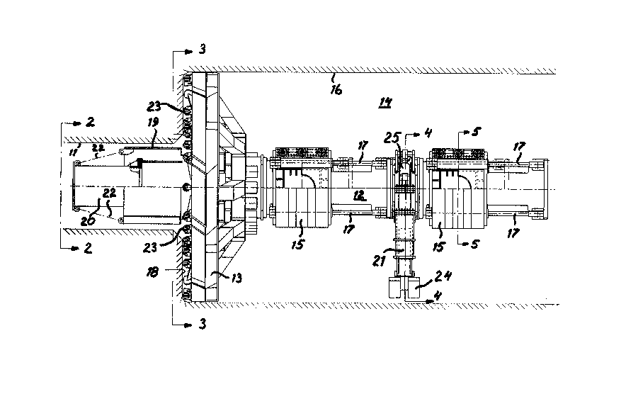
An embodiment of the invention is described below with reference to theaccompanying drawings in which fig 1 shows a tunnel boring machine according
to the invention from the side partly in section. Fig 2 shows a view
according to 2-2 in fig 1. Fig 3 shows a view according to 3-3 in fig 1. Fig
4 shows a view according to 4-4 in fig 1 partly in section. Fig 5 shows a
section according to 5-5 in fig l.
The tunnel boring machine for reaming the pilot tunnel 11 shown in the
drawings comprises a machine housing 12. The machine housing is built up
from a number of modules through which the machine in a relatively simple
way can be rebuilt to be adapted to different requirements in different
tunnels. The shown tunnel boring machine is provided with two units prcvided
with clamping shoes 15 for clamping the machine in the tunnel 14. The
clamping shoes act against the tunnel wall 16. The clamping shoes are
movable relative to machine housing 12 in the longitudinal direction of the
tunnel by means of hydraulic cylinders 17. A boring head 13 is rotateably
mounted on machine housing 12. The boring head is rotated relative to the
machine housing by one or more, not shown, electric motors. Boring head 13
is pressed against tunnel front 18 by means of hydraulic cylinders 17. A
unit provided with support legs 21 is mounted between the units with
clamping shoes 15. By means of these support legs, comprising hydraulic
cylinders, the tunnel boring machine is aligned vertically. The different
machine housing parts and the boring head are provided with flanges having
utl~9016

203~18~
standard form so that the different modules can be exchanged without
extensive design work. Machine housing 12 is at its front end provided with
a projecting part which extends into the pilot tunnel 11. This projecting
part comprises a part 20 being fixed relative to the machine housing and a
shield 19. Shield 19 is by means of wires or chains 22 connected with fixed
part 20. As a result shield 19 is moved into pilot tunnel 11 when tunnel 14
is bored. The purpose of shield 19 is .o prevent that blocks broken loose at
the transition between tunnel 14 and pilot tunnel 11 fall down and get stuck
between boring head 13 and tunnel front 18. Boring head 13 is provided with
a number of cutters 23 for crushing of the rock. These cutters are worn and
must be exchanged at intervals. For this purpose shield 19 can be separated
from the fixed part 20. After separation boring head 13 can be moved
backwards to give access to the cutters. Shield 19 then remains as
protection at the transition between tunnel 14 and pilot tunnel 11.
As shown in fig 4 support legs 21 are provided with feet 24. Hydraulic
cylinders 25 are connected between support legs 21 and machine housing 12.
Cylinders 25 make it possible to turn machine housing 12 about the
longitudinal axis of the tunnel when clamping shoes 15 are not in engagement
with tunDel wall 16. Through this it is possible to counteract the turning
which the tunnel boring machine often encounters as a result of reaction
forces during the boring.
Horizontal control of the ~unnel boring machine is obtained by means ofhydraulic cylinders 27 which move the machine housing 12 relative to
clamping shoes 15. When the adjustment has been done clamping is obtained by
pressurization of pistons 26.
utl89016

Representative Drawing
A single figure which represents the drawing illustrating the invention.
Administrative Status

2024-08-01:As part of the Next Generation Patents (NGP) transition, the Canadian Patents Database (CPD) now contains a more detailed Event History, which replicates the Event Log of our new back-office solution.

Please note that "Inactive:" events refers to events no longer in use in our new back-office solution.

For a clearer understanding of the status of the application/patent presented on this page, the site Disclaimer , as well as the definitions for Patent , Event History , Maintenance Fee  and Payment History  should be consulted.

Event History

Description Date
Inactive: IPC from MCD 2006-03-11
Time Limit for Reversal Expired 1998-11-16
Application Not Reinstated by Deadline 1998-11-16
Deemed Abandoned - Failure to Respond to Maintenance Fee Notice 1997-11-17
Inactive: Abandon-RFE+Late fee unpaid-Correspondence sent 1997-11-17
Application Published (Open to Public Inspection) 1991-05-23

Abandonment History

Abandonment Date Reason Reinstatement Date
1997-11-17
Owners on Record

Note: Records showing the ownership history in alphabetical order.

Current Owners on Record
ATLAS COPCO CONSTRUCTION AND MINING TECHNIQUE AB
Past Owners on Record
HELMUT DICK
OLOV ANDERSSON
SVERKER HARTWIG
Past Owners that do not appear in the "Owners on Record" listing will appear in other documentation within the application.
Documents

To view selected files, please enter reCAPTCHA code :


To view images, click a link in the Document Description column (Temporarily unavailable). To download the documents, select one or more checkboxes in the first column and then click the "Download Selected in PDF format (Zip Archive)" or the "Download Selected as Single PDF" button.

List of published and non-published patent-specific documents on the CPD .

If you have any difficulty accessing content, you can call the Client Service Centre at 1-866-997-1936 or send them an e-mail at CIPO Client Service Centre.

({010=All Documents, 020=As Filed, 030=As Open to Public Inspection, 040=At Issuance, 050=Examination, 060=Incoming Correspondence, 070=Miscellaneous, 080=Outgoing Correspondence, 090=Payment})


Document
Description 
Date
(yyyy-mm-dd) 
Number of pages   Size of Image (KB) 
Drawings 1991-05-22 3 93
Abstract 1991-05-22 1 7
Claims 1991-05-22 1 25
Descriptions 1991-05-22 2 76
Representative drawing 1998-07-23 1 35
Reminder - Request for Examination 1997-07-15 1 117
Courtesy - Abandonment Letter (Maintenance Fee) 1997-12-14 1 186
Courtesy - Abandonment Letter (Request for Examination) 1998-02-09 1 173
Fees 1996-11-17 1 30
Fees 1995-10-30 1 73
Fees 1993-10-25 1 50
Fees 1994-10-25 1 69
Fees 1992-10-19 1 42