Note: Descriptions are shown in the official language in which they were submitted.
203034 1
The present invention relates to a disk device as one of
external memory devices of a computer, and more specifically
to disk cleaning.
Aspects of the prior art and present invention will be
described by reference to the accompanying drawings, in
which:
FIG. 1 is a block diagram illustrating an embodiment of
a disk device including a cleaning device according to the
present invention;
0 FIGS. 2 and 3 are views each illustrating conditions
under which dust adheres to the rear end of a slider;
FIG. 4 is a view illustrating conditions under which the
slider is sought;
FIG. 5 is a flowchart illustrating the operation of the
present invention;
FIGS. 6 and 7 are views each illustrating a disk which
is preferable for application of the present invention; and
FIGS. 8 through 11 are views each illustrating problems
in a prior disk device.
O Referring to FIGS. 8 through 11, there are illustrated
operations of a magnetic disk and a magnetic head in a
magnetic disk device, respectively. In each figure,
designated at 1 is a magnetic disk, 2 is a slider for holding
a transducer that is to record/regenerate information on/from
the disk 1, 3 is a support spring for forcing the slider 2 to
follow up the disk 1, 4 is a tapered portion provided on the
slider 2, 5 is an arrow indicating the direction of rotation
of the disk 1 at recording and regeneration on the disk, 6 is
an arrow indicating the direction of seeking by the slider 2,
0 7 is dust, and 8 is a non-recording region on the disk 1.
Operation of the above arrangement is as follows:
As illustrated in FIG. 8, the slider 2 is pushed-against
the disk 1 by the support spring 3 at a static state,
- 2 - 2030341
and is allowed to make static contact with the disk 1.
Once the disk 1 starts to rotate in a direction
indicated by the arrow 5, an air stream is produced on the
surface of tlle disk 1 and is allowed to strike the tapered
portion 4 as a wind pressure, which portion is thereby
pushed up to float the slider 2.
The slider 2 is allowed to float and stop generally in
a non-recorded region ~ o~ the disk 1 as indicated by a
dotted line in ~IG. 9. As the disk 1 goes into steady
rotation, the slider 2 moves to a position indicated by a
solid line 2 in the figure, and selects a track arranged
coaxially on the disk 1 while seeking those tracks in the
direction indicated by the arrow 6, to record/regenerate
information on/from the track.
For the lifted attitude of the slider 2, the slider 2,
which is pushed up and lifted by wind pressure excerted on
the tapered portion 4 as shown in FIG. 10, is lifted to a
higher position on the leading edge side where the tapered
portion 4 has been provided, while being lifted to a lowest
position, a height hz, on the trailing edge side.
Additionally, as ill~strated in ~IG. 10, any dust such
as dirt (hereinafter referred to dust ) existent around the
disk 1 is entrained by the air flow with the rotation of the
disk 1 to strike the tapered portion 4 of the slider 2
together with the air flow, and allowed to adhere partly to
3 20303~1
the tapered portion 4. This causes such dust to be
accumulated on the tapered portion 4 located on tbe back
side of the slider 2 for a long period of time, as
illustrated in ~IG. 11.
In the prior magnetic disk device, any dust is
accumulated on the tapered portion with the elapse of time
as described above. The slider is however difficult to be
cleaned. Particularly, in a closed magnetic device capable
of dealing with a recent trend of making the device high
density, it is impossible to clean the interior of Ille
device without decomposing the device, and accumulated dust
interrupts the operation of the tapered portion to cause the
unstable lifted attitude of the slider and hence head
crushing.
To solve such a difficulty, there is l~nown as a prior
art "a magnetic disk device" disclosed in the device of
Japanese Utility Model Laid-Open No. 62-57999. In tllis
prior art, any dust adhering to a disk surface is scattered
by a slider by rotating the disk at a low rotational speed
in the same direction as the direction of rotation of the
disk during recording and regeneration, and bringing the
slider near to the disk surface to repeatedly seek the disk
several times.
Accordingly, also in the prior device, although
cleaning of the disk surface is likely to some extent, the
203034 1
dust will be still accumulated on a tapered portion, so that
removal of any dust accumulated on the tapered portion is
difficult, causing a malfunction of the tapered portion.
Thus, there is still a problem that head crushings may occur.
In one aspect, the invention provides a cleaning device
in a disk drive comprising: a disk having a recording region
and a non-recording region, the surface of the non-recording
region having a dust attracting surface means comprising a
lubricating or roughened layer for enhancing dust removal; a
slider adapted to float by an air stream on the surface of
said disk and positioned by an actuator through a spring and
an arm; a head mounted on said slider; positioning means for
positioni~g said slider at a predetermined track position on
the disk by controlling said actuator; first motor control
means for driving a motor serving to drive said disk in a
first direction for writing/reading of information to the
recording region of the disk; second motor control means for
rotating said disk in the opposite direction to the first
direction for cleaning dust from the surface of the recording
region of the disk; and seeking means for forcing the slider
to move across the entire recording region of the disk during
the opposite direction rotation of the disk causing any dust
on the disk to adhere to the slider and thereafter to move
the slider to the non-recording region of the disk during
rotation of the disk in the first direction to contact the
surface means for removal of any dust from the slider.
-- 4
20 3034 1
In a further aspect, the invention provides a method for
cleaning a disk in a disk drive, comprising the steps of:
(a) rotating the disk oppositely to an ordinary
direction of a read/write operation;
(b) cleaning a recording region on the disk by sliding a
slider across the entire recording region while the disk is
rotated oppositely to the ordinary direction causing dust on
the recording region to adhere to the slider; and
(c) cleaning dust from the slider by contacting the
slider to a surface of a non-recording region having a layer
of material thereon for removing dust while the disk is
rotated in the ordinary direction.
In a still further aspect, the invention provides a
method for cleaning a magnetic disk in a disk drive,
comprising the steps of:
(a) rotating the magnetic disk oppositely to an ordinary
direction of read/write operation;
(b) moving a slider across an entire recording region of
the disk during the opposite direction rotation causing dust
on the recording region to adhere to the slider:
(c) thereafter moving the slider to a non-recording
region of the disk; and
(d) cleaning dust from the slider by repeatedly starting
and stopping rotation of the disk in the ordinary direction
and contacting a surface of the non-recording region having a
layer of material thereon for removing dust with the slider
-- 5 --
203034 1
for removing dust from the slider.
The invention also provides a cleaning device in a disk
drive comprising:
a disk storage device having a recording region and a
non-recording region, the non-recording region including a
rough surface layer;
a slider movable across the surface of the disk and
positioned by an actuator;
a head mounted on the slider;
a motor, operatively connected to the disk, to rotate
the disk;
a motor control mec~n;~m, connected to the motor, to
control the direction which the motor rotates the disk;
a seeking mechanism; operatively connected to the
slider, to cause the slider to move over the entire recording
region to pick up dust therefrom while the disk is rotated in
a first direction and thereafter to cause the slider to move
to the non-recording region and contact the rough surface
layer to remove dust from the slider while the disk is
rotated in a second direction, opposite to the first
direction; and
a counter, coupled to the motor control mech~n;~m and
the seeking mechanism, to count a number of read/write
operations such that the seeking mech~n;~m does not cause the
slider to move over the recording region to pick up dust
- 5a -
203034 1
therefrom till after a predetermined number of read/write
operations.
A further embodiment of the invention provides a method
for cleaning a disk in a disk drive~, the disk drive having a
tr~nCAl~-er for reading/writing information from the disk and
a slider for carrying the trAnCAllcer, the disk drive
rotating the disk in a first direction during read/write
operations, the disk having a recording region whereon
information is stored and a non-recording region, the method
comprising the steps of:
(a) rotating the disk oppositely to the first
direction;
(b) cleA~inq the recording region on the disk by moving
the slider across the entire recording region as the disk is
rotated in the direction opposite to the first direction
such that dust from the recording region of the disk adheres
to the slider;
(c) cleaning the slider by positioning it above the
non-recording region and stopping the rotation of the disk
so that dust is displaced from the slider;
(d) restarting the rotation of the disk; and
(e) repeatedly stopping and starting the rotation of
the disk a predetermined number of times.
In what follows, an embodiment of the present invention
will be described with reference to the accompanying
drawings. Referring to FIGS. 1 through 5, there is
- 5b -
C-
- 203034 1
illustrated an embodiment of a disk device including a
cle~nin~ device, and a cleaning method, respectively. The
same symbols as those illustrated in FIGS. 8 through 11
indicate the same or correspon~ing portions.
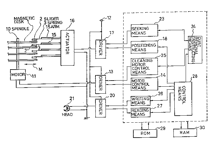
Referring to FIG. 1, which is the block diagram of the
~\`
-- 2030341
- 6 -
embodiment Or the disk device having the cleaning device
according to the present invention, a plurality of magnelic
disks 1 are attached to a spindle 10 which is forwardly or
backwardly rotated or stopped by a motor 11. The motor 11
is driven and stopped by a driver 13 connected to a power
supply, and the driver 13 is controlled by motor control
means 14. An arm 15, which supports a spring 3, is driven
by an actuator 16. On the basis of operation of the
actuator 16, a slider 2 is shifted radially (in the
direction of an arrow M) of the magnetic disk~ qnd G~
The actuator 16 is controlled by positioning means 1
through a driver 17 connected to the power supply.
Designated at 26 is writing means for writing any
information on a magnetic head 21 by supplying power to a
magnetic head 21 through a driver 20, and 27 is reading
means for reading through the driver 20 any information
read by the magnetic head 21. Additionally, designated at
23 is seeking means for seeking the slider 2 by driving the
same according to an instruction from dust removal
instructing means 24, 25 is cleaning motor control means for
reversely rotating the motor 11 and repeatedly driving and
stopping the same by driving the same according to an
instruction from the dust removal instructing means 24, 2
is control means, 29 is a ROM, and 30 is a RAM.
In FIGs. 2 and 4, an arrow designated at 9 indicates
_ 7 _ 2030341
the direction of rotation of the disk 1 at self-cleaning,
that is an opposite direction to the direction of rotation 5
of the same at recording and regeneration. Further, a
symbol hl designates a floating height of the slider 2 when
the disk 1 is rotated at a low rotational speed in the
direction of the arrow 9. The height h, is sufficiently
smaller than a heigllt h2 shown in ~IG. 10.
In succession, the operation of the embodiment will be
described.
For write/read operation of information, the motor
control means 14 is driven by the control means 2~ to drive
the motor 11 forwardly and hence rotate the disk 11
forwardly, say in the direction of the arrow 5. llereby, the
slider 2 is driven to float by h2. Successively, the
positioning means 18 is driven to position the slider 2
from the non-recording region 8 to a predetermined track in
a recording region 8A for write/~ead operation of
information by the writing means 26 or the reading means 27
Now, the operation will be further described with
reference to the flowchart of FIG. 5.
In the present invention, a self-cleaning of the
magnetic disk is performed prior to the start of the
aforementioned write/read operation. For the self-cleaning
the cleaning motor control means 25 is actuated by the dust
removal instructing means 24 to rotate the disk 1 at a low
- 8 - 20303~
rotational speed in the opposite direction to tllat
indicated by the arrow 9, i.e., in the opposite direction to
the ordinary read/write direction (Step 1).
With such rotation of the disk 1, an air flow produced
on the surface of the disk 1 as illustrated in PIG. 2 h;ts
the slider 2 as a wind pressure to float the same. Ilowever,
the tapered portion 4 is not located on the side of the
trailing edge, so that the floating height 11l of the slider
2 is considerably smaller than the floating height hz and
hence the slider 2 floats on the surface of the disk 1,
separated away only a fine distance from tlle same.
Ilerein, such a rotational speed of the disk 1 in the
reverse direction indicated by the arrow 9 may be about 500
1,000 rpm although an ordinary one is 3.600 rpm.
Purther, the reason to rotate the disk 1 at the low
rotational speed is as follows: the floating height of the
slider 2 is substantially determined by a relative speed
between the disk 1 and the slider 2 if the shape of the
slider remains unchanged, and the floating height of the
slider 2 is higher as the relative speed is higher.
Ilowever, any floating dust, which is very small in size,
simply passes through between the disk 1 and tlle slider 2
when the floating height is greater, and hence does not
adhere to the slider 2 so much. ~ccordingly, the disk 1 is
rotated at the low rotational speed to permit the slider 2
9 20303~1
to float at a low height for allowing any dust to be liable
to adhere to the slider 2.
In succession, the disk 1 is rotated in the recording
region 8A to permit any coming dust to positively adhere to
the trailing edge side of the slider 2. Ilerein, the
seeking means 23 is actuated to repeatedly seek the track
surface of the disk 1 in the recording region 8A in the
direction of the arrow 6 for cleaning of the recording
region 8A on the disk 1 (Step 2).
With the completion of the cleaning, the seeking means
23 moves the slider 2 to the non-recording region 8 which is
not used during the recording and regeneration (Step 3).
The cleaning motor control means 25 repeatedly drives and
stops the motor in the non-recording region 8 to repeatedly
perform the CSS (Contact-Start-Stop) of the slider 2 to the
magnetic disk 1. Ilerein, the disk 1 is rotated in the
ordinary direction of rotation. Ilereby (Step 4), any dust
adhering to the trailing edge is forced to positively fall
on the disk surface for cleaning the slider 2, as
illustrated in FIG. 3. Ilerein, the write/read operation of
the information is interrupted during the actuation of the
dust removal instructing means 24. Additionally, the
foregoing CSS means that the slider 2 makes contact with
the disk surface during the stop of the disk and it floats
as the speed of rotation of the disk increases. Furttler,
2030341
-1 O-
although the cleaning of the slider 2 has been described as
being done in the same direction as the ordinary direction
of the rotation of the disk 1, this originates from a fact
that exfoliating force to any dust is produced in the
opposite direction to the adherence of the dust to ease the
falling of the dust Additionally, for the cleaning of the
slider 2, the disk 1 may be reversed in ils rotation at
each CSS. Furthermore, the falling of any dust may be
secured by making thick a lubricating layer in the non-
recording region 8 or by properly varying the surface
roughness of that region. More specifically, there is a
property that the slider 2 is liable to attract any dust as
the lubricating layer 8a is made thicker Accordingly, the
slider 2 can easily attract any dust in the non-recording
region 8 with such construction as illustrated in FIG. 6.
liereby, any dust on the slider 2 is liable to fall with the
repeated CSS. Herein, numeral 8b is a substrate and 8c is
a magnetic layer, in FIG. 6.
Additionally, as illustrated in FIG. 7, frictional
force is made greater to ease the falling of the dust on the
slider 2 provided that the surface of the non-recording
region 8 is roughened. Although, in FIG. 7. the roughened
surface was illustrated as extending over the whole non-
recording region 8, the surface may be existent on a track
partially in the non-recording region 8, which track may be
- 1 1 - 203034~
used as a track only for cleaning the slider. Further, a
combination of FIG. 6 and 7 may be used.
With the operation described above, once the self-
cleaning of the disk 1 and tlle slider 2 is completed, the
control means 28 steadily rotates the disk 1 in tlle
direction indicated by the arrow 5 for recording and
regeneration of information on the disk 1.
llerein, the timing to perform the self-cleaning may be
set such that it is performed each time the write/read
operation is completed or every predetermined time, not
limieed to the time that the device is actuated for the
write/read operation. Moreover, the self-cleaning may be
started when the write/read operation is performed a preset
number of times which is counted by a write/read starting
counter provided anew.
Furthermore, the repeated actuation and interruption of
the motor by the cleaning motor control means 25 after the
completion of the cleaning may be performed at the
recording region without shifting the slider 2 to the non-
recording region 8 and may scatter any falling dust in the
recording region 8A to the outside by making use of
centrifugal force.
The present invention, as described above, has an
advantage that the adhesion of the dust to the tapered
portion can be prevented, since the cleaning is performed
~ - 1 2 - 20303911
by rotating the disk in the direction opposite to the
rotational direction at recording and regeneration, so that
a highly reliable disk device having a cleaning device and
a c 1 ean i ng me thod can be prov i ded .