Note: Descriptions are shown in the official language in which they were submitted.
r~ - 10 2 7--4
30553
. ~
ADJUSTABLE $P~INT ASSEMBLY
BACKGROUND OF THE INVENTION
; Field of the Invention:
; This invention relates to an adjustable splint
assembly. More particularly, this invention relates
to the combination of an adjustable splint device and
an external fixator device, useful for therapeutical
treatment of impairments in body joints and the like
from flexion and extension contractures, weakness in
the supporting musculature, or some other malady
inhibiting the integrity of the body joint in
accomplishing flexion or extension.
People often develop flexion and extension
contractures in body joints such as knee joints or
elbow joints from many and various causes. Weakness,
disuse, fractures, surgeries, traumatic injuries,
e` illness and other causes have been known to cause loss
of ability to extend or flex the knee joint or elbow
joint. With respect to surgery in particular, a
common, adverse post-operative effect of Ilizarov
orthopedic surgery on a leg or an arm, is knee joint
or elbow joint contracture or loss of range of
motion. In the early 1950s, Prof. Ilizarov of the
USSR developed an external fixator device for treating
bone injuries using essentially a bloodless surgery
technique. The device consists of two or more metal
rings surrounding the limb to be treated, with wires
surgically implanted through the skeletal part and
connected to the metal rings. Tension is maintained
between the rings in order to place forces on the bone
..
,., c~7
` ~ .
2030S~3
and facilitate treatment. In the United States, this
device has been approved for treatment of the
following indications:
1. Fracture fixation.
` 2. Pseudoarthroses of long bones.
3. Limb lengthening.
4. Correction of bony or soft tissue deformities
or defects.
As mentioned above, a common effect of this treatment
is joint contracture or loss of range of motion.
However, no device presently exists to reduce flexion
contractures of knee joints or elbow joints that often
result f~rom Ilizarov surgery, by adjustable,
quantifiable pressure as does the adjustable splint
assembly described herein.
Many splint devices and mechanisms have been
designed to be influential at the knee, elbow, etc.,
either for support or for mobilizing the joints.
Illustrations of such devices are those described in
U.S. Patent Nos. 3,055,359; 3,785,372; 3,799,159;
3,928,872; 4,397,308; 4,485,808; 4,508,111; 4,538,600;
4, 657,000. However, all of these devices are not
designed to reduce knee joint or elbow joint flexion
or extension contractures resulting from or related to
surgery using an Ilizarov External Fixator, nor can
these devices be tolerated by the patient population
for a long enough period to effectively reduce a
contracture.
OBJECTS OF THE INVENTION
Accordingly, it is an object of the invention to
. provide an improved splint assembly incorporating a
r fixator device such as an Ilizarov External Fixator,
for reducing flexion and extension contractures about
a body joint, particularly a knee joint or an elbow
joint.
20305~3
. --3
Yet another object of the invention is to provide
such an adjustable splint assembly incorporating an
external fixator device, which allows easy gradual
adjustment to the quantifiable force desired on an
extremity acting across a body joint, particularly a
knee joint or an elbow joint.
A further object of the invention is to provide
an improved adjustable splint assembly, for providing
support to a limb around a body joint, particularly a
limb around a knee joint or an elbow joint.
SUMMARY OF THE INVENTION
; These and other ob;ects of the invention are
obtained by an adjustable splint assembly comprised of
an adjustable splint device and a fixator device, said
adjustable splint device comprising a distal strut and
a proximal strut pivotably connected to said distal
strut, one of said struts having at one end a
pivotably mounted head portion defining a cam surface,
an adjustable biasing means mounted within the other
strut and biased into engagement with said cam surface
; for applying a quantifiable force tending to
approximate or align said distal and proximal struts,
said fixator device comprising a right ring and a left
ring, two or more surgical wires for implanting
~; through a bone, with said wires connected at each end
to the periphery of the right ring and crossing each
other substantially near the center axis of said right
ring, two or more surgical wires similarly connected
to and crossing within the left ring, means for
connecting said surgical wires to the right ring and
'r left ring, an upper rod connected at one end to the
left ring and at the other end to the right ring, a
lower rod connected at one end to the left ring and at
the other end to the right ring on the sides of the
rings opposite the upper rod, means for connecting
:. ,
=--==
_4_ 2030~5~
said upper rod and lower rod to the right ring and
left ring, a clamping assembly slidably mounted on the
distal strut of said adjustable splint device, means
for securing said clamping assembly to the distal
strut, means for connecting said clamping assembly to
the right ring of said fixator device, and means for
securing said adjustable splint assembly to a limb.
In a preferred embodiment, the present invention
comprises a pair of distal struts, a pair of proximal
struts and an Ilizarov External Fixator ring, each
member of the pair of distal struts being pivotably
connected to a member of the proximal struts, with
said members of the proximal pair being spaced apart a
distance to accommodate limb parts proximal to the
limb joint and said members of the distal pair being
spaced apart a distance to accommodate attachment to
opposite sides of the Ilizarov ring, at ieast one of
said struts having at one end a pivotably mounted head
portion defining a cam surface, an adjustable biasing
means mounted within the strut pivotably connected to
said cam surface-containing strut and biased into
engagement with said cam surface, for applying a
quantifiable force tending to align or approximate the
cam surface-containing strut with the adjustable
biasing means containing strut, each member of the
pair of distal struts being slidably mounted within a
clamping assembly, means for tightening said clamping
assemblies to grasp securely the distal struts, each
of said clamping assemblies connected to the Ilizarov
External Fixator ring, means for connecting said
clamping assemblies to the Ilizarov External Fixator
ring, and means provided at least said pair of
proximal struts for securely holding therebetween
proximal parts of a limb.
In one aspect of the invention, the adjustable
splint is provided with a telescoping wire assembly on
,'
;
203Q5~3
the proximal struts whereby the adjustable splint is
secu~ed to the limbs. This slidably adjustable wire
assembly feature enables the splint device of the
invention to accommodate various limb lengths. In
addition, novel snap-on comfort pads attachable to the
struts of the splint device provide greater patient
comfort.
Another aspect of the invention involves a novel
cuff for attaching the splint device to a limb which
cuff is designed to accommodate limbs of varying
circumferences.
BRIEF DESCRIPTION OF THE DRAWINGS
The invention will appear more clearly from the
following detailed description when taken in
connection with the following drawings which show by
way of example a preferred embodiment of the
invention:
In the Drawings:
Figure 1 is a side perspective view of the
adjustable splint for reducing flexion contractures
incorporating an Ilizarov External Fixator, showing
~;n;~um deflection of the proximal strut;
Figure 2 is a side perspective view of the
adjustable splint for reducing flexion contractures
incorporating an Ilizarov External Fixator, showing
m~;mum deflection of the proximal strut;
Figure 3 is a top perspective view of the
adjustable splint for reducing flexion contractures
incorporating an Ilizarov External Fixator;
Figure 4 is a front perspective view of an
Ilizarov External Fixator ring together with two
clamping assemblies for connecting to the distal
struts of the adjustable splint;
Figure 5 is a side perspective view of an
Ilizarov External Fixator ring and means connecting
~ -6- ~03055~
same to two clamping assemblies;
'Figure 6 is a perspective, exploded view in part
of an Ilizarov External Fixator ring together with the
adjustable splint for reducing flexion contractures;
Figure 7 is a perspective view of one distal and
one proximal strut assembly of the adjustable splint
of the invention for reducing flexion contractures
wherein a strut is broken away to show the adjustable
spring-loaded means mounted therein;
Figure 8 is a perspective, exploded view of the
spli~t device of Figure 6;
Figure 9 is a perspective view of the splint
device provided with a "break apart" wire assembly for
mounting of the means by which the device is secured
to the limb;
Figure 10 is a cuff designed for attachment to !
the wire assembly shown in Figure 9;
Figure 11 is a perspective view of one distal and
one proximal strut assembly of the adjustable splint
of the invention for reducing extension contractures
wherein a strut is broken away to show the adjustable
spring-loaded means mounted therein;
Figure 12 is a perspective view of the splint
device provided with a telescoping slidable adjustable
wire assembly for mounting of the means by which the
device is secured to the limb;
Figure 13 is a plan view of the outside of
another cuff for attachment to the wire assembly
designed to accommodate limbs of varying
circumferences;
Figure 14 is a perspective view of the cuff shown
in Figure 13;
Figure 15 is a perspective view of a wedge-type
comfort pad for use in combination with the adjustable
splint of the invention; and
Figure 16 is a perspective view of a
; . ~
_7_ 2030~53
rectangular-type comfort pad for use in combination
with the adjustable splint of the invention.
DESCRIPTION OF THE PREFERRED EMBO~IMENTS
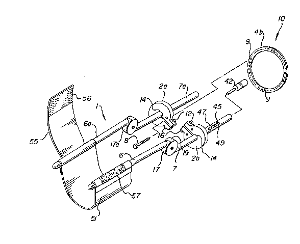
Referring to Figures 1-3, an adjustable splint
device 1 is shown in combination with an Ilizarov
External Fixator 3 in accordance with the present
invention. Shown in a typical configuration (e.g.,
attached to a leg), the Ilizarov External Fixator 3 is
comprised of a left full ring 4a and a right full ring
4b encircling a patient's limb (e.g., a femur),
wherein said rings 4a and 4b are surgically implanted
into the limb by passing one or more wires 36 (see
Fig.4) through the bone and attaching said wires to
connectors 33 located on each ring. Directing
attention to Figs. 1 and 4, the right full ring 4b
contains a series of holes to accommodate threaded
rods 5a and 5b. The left full ring 4a contains
similar holes to accommodate the opposite ends of said
threaded rods. In a preferred configuration, the
threaded rods are positioned one above and one below
the patient's limb so that clamping assemblies 2a and
2b can be attached to the right full ring 4b at points
near 270~ and 90, respectively, around the
circumference of said ring. The clamping assemblies
2a and 2b are attached to the right full ring at holes
9 using bolts 8 and nuts 10 (see Figs. 4-6). Said
clamping assemblies 2a and 2b are thereafter connected
securely in position in order to adapt the adjustable
splint device 1 to the Ilizarov External Fixator 3.
Referring to the figures, the adjustable splint
device 1 is comprised of proximal struts 6 and 6a and
distal struts 7 and 7a. The adjustable splint device
1 is adapted to the Ilizarov External Fixator 3 by
passing said distal struts 7 and 7a through holes 14
(see Figs. 4-6) in the centers of left clamping
~ . -
20~0~5~
assembly 2a and right clamping assembly 2b,
respectively, and tightening bolts 12 and nuts 16
which compress the clamping assemblies to hold distal
struts 7 and 7a securely to the right full ring 4b.
Although the configuration as shown provides clamping
assemblies to connect the adjustable splint device to
-
the Ilizarov External Fixator, it should be understood
that any appropriate connecting means may be used to
provide such an adaptation. For example, an Ilizarov
ring could be manufactured providing a built in means
for connecting the adjustable splint to the ring.
Referring to Figs. 6-8, proximal strut 6 contains
a rounded head portion 17 and distal strut 7 contains
a socket head portion 19 which receives head portion
17 for pivotal engagement therewith. Rounded head
portion 17 is cut away to define a cam surface 20 and
is provided with an axial surface recess 23. A first .
surface plate 25 having a screw hole 27 covers one
side of the combined head portions 17-19 and a second
plate member 28 having a threaded protruding member 29
(see Fig. 8) covers the other half of the combined
head portion 17-19. When surface plate member 28 is
positioned over the combined head portion 17-19
protruding member 29 projects through the axial
circular recess 23 and receives a screw 31 through
screw hole 27. Proximal strut 6a and distal strut 7a
are similarly pivotably connected by corresponding
members bearing like numbers but carrying the
distinguishing suffix "a".
The proximal and distal struts may be constructed
of any material of sufficient strength such as
plastic, metal, wood and the like. Particularly
preferred are struts made of stainless steel metal.
At least one of the struts should be at least
partially hollow so as to house therein the adjustable
spring mechanism of the invention. As shown in the
.
.
2030S53
g
drawings, the distal struts are tubular in
construction and the proximal struts are solid. If
desired, however, all of the struts can be tubular in
construction so as to provide a lightweight product.
Also if desired, each of the proximal struts 6 and 6a
can be comprised of two telescoping portions as shown
by the single proximal strut 6 depicted in Fig. 12 so
as to permit lengthening and shortening of the
proximal struts. Directing attention to Fig. 12,
strut 6 is comprised of telescoping portions 150 and
~51. The inner portion 150 is provided with a series
of threaded holes 152 and the outer portion 151 with
holes and threaded holes, respectively, through which
screw 153 passes for threaded engagement with a
coincident hole 152. Such a telescoping feature
provides a splint which can be adjusted to several
different lengths allowing the splint to fit a greater
number of individuals. It should be understood that
in this embodiment the splint device combination of
the invention will include a series of spring abutting
members 39 (see Fig. 8) of varying lengths so as to
accommodate different limb lengths.
The adjustable spring-loaded mechanism designated
generally as 30 may be provided in either the proximal
or the distal struts. Preferably, however, it is the
distal struts 7 and 7a that are provided with the
adjustable spring mechanism.
The adjustable spring mechanism 30 is comprised
of a spring 32 to which is attached a nose element 34
that bears on cam surface 20. Coil or clock springs
are generally preferred but in some instances leaf
springs are advantageously employed. An adjustable
screw means indicated generally as 35 abuts the other
end of the spring 32 and produces a quantifiable force
which tends to either extend (i.e., align the proximal
strut 6 with the distal strut 7 and proximal strut 6a
-
-lO- 203~S3
with distal strut 7a in a parallel fashion) as shown
in Figs. 2 and 7 or to approximate (i.e., bring
together the proximal strut 6 with the distal strut 7
and proximal strut 6a with distal strut 7a) as shown
in Figure ll. As ~ mum deflection or flexion is
approached, tension is created in the compression
coiled spring 32. The adjustable screw means 35 is
comprised of an "Allen" head screw or slotted head
screw 37 threaded to a spring-abutting member 39. The
"Allen" head screw is fixed within distal strut 7 by
screw 43. The "Allen" head screw 37 receives and is
turned by an "Allen" socket wrench 42 (see Fig. 6)
whereas a slotted head screw is adjustable with a
conventional screwdriver blade. The turning of the
screw creates greater compression of spring 32 thereby
exerting greater force on the cam surface 20 of the
proximal strut 6 to exert a one way tension. The
tension capability of the spring mechanism can range
from 0 pounds tension up to the maximum tension
capability of the spring. In general, the tension of
the spring mechanism will range from o pounds tension
up to lO pounds of tension and the tension exerted by
the spring can be varied at any point of joint range
of motion, say from 60 flexion to 0 flexion of the
joint.
Whereas the specific joint range of motion to
which tension can be exerted is preferred to be 600
flexion through 0 flexion for reducing flexion
contractures in the knee and elbow, the joint range of
motion at which tension can be applied can vary to
nearly any degree in the 360O circular range simply by
varying the point of attachment of the inner portion
of strut 6 to rounded head portion 17 and by varying
the point of attachment of strut 7 to socket head
portion l9. Likewise, the same variations apply to
struts 6a and 7a.
. .
11 20305~3
The purpose of varying the point in the joint
range to which tension is applied is obvious when you
consider that different illnesses and injuries cause
different types of limitations at different degrees of
joint ranges of motion thereby making necessary
different points in the joint range at which tension
must be applied to improve their condition. Another
example would be when reducing an extension
contracture of the knee the desired range of motion to
which tension would be applied would range from 40~
flexion to 130 flexion. The spring mechanism can be
calibrated to exert the desired range of tension. The
calibration can be effected by providing
spring-abutting member 39 with a poundage indicator
line 45 and a calibration scale 47 about the distal
strut 7 which scale has a slot 49 through which the
. .
poundage indicator 45 is visible.
While the preferred adjustable biasing means of
the invention is a spring means such as described,
equivalent biasing means such as air or hydraulic
powered biasing means will readily come to the mind of
those skilled in this art.
Any suitable means can be utilized to secure
pivotably mounted struts 6 and 6a to the limb so that
they lie lateral to the joint with the axis of
rotation coinciding as closely as possible to the axis
of rotation of the joint. As shown in the figures,
the securing means comprise a proximal cuff 51
attached to and extending between proximal strut 6 and
proximal strut 6a. The length of the proximal cuff 51
is of sufficient distance to comfortably accommodate
the limb part proximal to the limb joint. An
overlying flap 55 is attached at one end to proximal
strut 6a and contains on its outer surface an
attaching means such as velcro hooks 56 by which t~e
flap can wrap about the proximal portion of the limb
_ J
, ~ .
2030~53
-12-
and be secured to the velcro loops 57 on the outer
surf~ce of the proximal cuff wrapped about proximal
strut 6. When wrapped around the limb and secured,
the cuff serves as a counterforce strap.
It should be understood that a single combined
strut, such as proximal strut 6 pivotably connected to
distal strut 7, can alone be utilized as a splint
device by securing proximal strut 6 by suitable means
to the lateral side of the limb to be treated, and
securing distal strut 7 by suitable means to the right
full ring 4b of the Ilizarov External Fixator 3.
Again, any suitable means for strapping or securing
the splint device of the invention can be used, for
example, by a proximal cuff of sufficient length to
wrap around the proximal portion of the limb being
treated. The strap 55 as well as the cuff 51 can be
secured to the struts in any suitable manner as by
sewing, tying, etc.
To facilitate the attachment of the cuff and
strap, however, it is preferred that wire assemblies,
designated generally in Fig. 9 as 72 and 76, be
fastened as by welding to struts 6 and 6a,
respectively. The wire assembly 72 is comprised of an
upper thin wire portion 93 and a lower thin wire
portion 92, each of which wire assembly portions
extend from one end of strut 6a to the other.
Similarly, wire assembly 76 is comprised of an upper
thin wire portion 90 and a lower thin wire portion
91. In the preferred embodiment shown in Fig. 12 the
shorter sides of the wire assemblies are of continuous
construction and bent for more secure attachment as by
welding to the struts. In the embodiment of Fig. 9
wire assembly 76 differs from wire assembly 72 in
being of the "break apart" type as will be explained
below so as to facilitate insertion and removal of the
cuff or strap for cleaning, replacing, etc. Thus,
~ .~
.
-13- 20~5S3
wire assembly 76 is comprised of an upper thin wire
portion 90 and a lower thin wire portion 91 both of
which are broken at 97 and 98, respectively, so that
the wire can be pulled apart slightly when the cuff or
strap is to be attached or removed. In the embodiment
of Fig. 12, however, both of the wire assemblies are
of the "break apart" type, but one wire portion on the
proximal struts, that is, two receiving wires contain
telescoping sections B and B'. Telescoping sections B
are internally threaded at one end for engagement with
threaded ends B'. This gives the wire fixture,added
strength. Normally, a wire assembly with telescoping
sections B and B', however, is only used on the side
of the strut which makes an angle of 65 when flexed.
When the adjustable splint is to be used for
e~tension of a joint, a strap 120 is provided between
struts 6 and 6a as shown in Fig. 9. Use of a strap
120 between struts 6 and 6a is often advisable in many
instances; particularly in reducing knee flexion
contractures. Strap 120 in these applications is
important in order to maintain optimal alignment of
the proximal struts along the parallel of the limb
part proximal to the joint. Strap 120 also helps
maintain the axis of rotation of the splint joint
assembly more coincident with the axis of rotation of
the body joint to which the splint is being applied.
Attachment of cuff 102, provided with a velcro
hooks section 108 and a velcro loop section 110 as
shown in Fig. lo, to the wire assemblies shown in Fig.
g may then be conducted in the following manner:
Loop end section 104 of cuff 102 is put on wire
portion 90 via break 97 with the velcro hooks section
108 and velcro loop section 110 facing outward. Edge
106 is taken over the limb and fed through and under
wire portion 93 of wire assembly 72, and then put back
on itself whereby velcro hooks 108 adhere to velcro
.j
-14- 2Q3Q553
loops 110. This secures one of the two cuffs needed
to fix the splint assembly to a limb about a joint.
The same procedure is used to attach a cuff or strap
to the wire sections 91 and 92.
Where but a single assembly of a proximal and
distal strut is to be used, the respective cuff and
strap is provided near each of their ends with
suitable securing means such as velcro hooks and
loops. It should be understood that while the
securing means are shown to be velcro closures, other
alternative closures such as snaps and the like can be
provided the cuff and strap.
Another novel cuff which can be used to secure
the splint device to the limb is shown in Figs. 13 and
14. Referring to these figures, the cuff 130 is of a
length sufficient to accommodate a limb part proximal
to the limb joint. The outside of cuff i30 is
composed of a spaced apart and alternating velcro loop
section 132 and a velcro hook section 134 each
followed by a zone therebetween containing both velcro
hook sections and velcro loop sections. Most
advantageously, the zones containing both hook
sections and loop sections are comprised of an
intermediate area 138 constituted of a velcro loop or
hook section identical to the preceding section,
flanked on each side by areas having velcro loop or
hook sections identical to the section of uniform
velcro hooks or loops that follow. Thus, in Fig. 13,
the zone following velcro loop section 132 is composed
of an intermediate velcro loop area 138 flanked on
each side by velcro hook areas 136. Velcro hook
section 134, on the other hand, is followed by a zone
having velcro hook area 142 flanked by velcro loop
areas 143. If a longer cuff is required, the next
zone would be of velcro loops only, etc.
Loop end section 144 of cuff 130 is provided with
'
;
:
- . ~
-: 2030~53
-15-
a stay-receiving means indicated generally as 146 into
which is inserted a plastic stay 147 to prevent any
collapsing that is likely to occur during use. Also,
the inside of cuff 130 contains multiple stay
receiving means 148. The cuff is shown in the figures
as rectangular in shape. It should be understood,
however, that the cuff can assume various curved
configurations so as to conform to the particular limb
to which it is attached. Attachment of cuff 130 to
the wire assembly and the patient's limb can be
effected as described above.
In a preferred embodiment of the invention, the
splint device is provided with snap-on comfort pads
shown in Figs. 15 and 16. The comfort pads are of two
types, the wedge-type of Fig. 15 and the
rectangular-type of Fig. 16. The wedge-type comfort
pad of Fig. 15 is composed of a wedge base 145
provided with a snap-on section comprised of a base
plate 150 containing spaced snap-on elements 152 and
152'. The rectangular-type comfort pad of Fig. 16 is
composed of a rectangular base 155 provided with a
snap-on section comprised of a base plate 157 and
snap-on elements 159 and 159'. The wedge base 145 and
rectangular base 155 may be constructed of any
suitable light weight material such as foamed
plastic. The wedge-type comfort pads are used only
when the adjustable splint of the invention is applied
to the lower extremities, e.g., the leg below the
knee. In this instance, two wedge-type comfort pads
are normally snapped onto the proximal struts, within
the wire assembly and between the limb and strut in a
fashion whereby the thick portion of each wedge is
proximal to the point of pivotable engagement of said
struts.
The rectangular comfort pads are similarly
snapped on the struts within the wire assembly and
-16- ~Q3Q~53
between the limb and the strut. Where the adjustable
splint of the invention is applied to a lower
extremity, two of the rectangular comfort pads will be
placed on the lateral sides of the lower extremity,
one on each of the proximal struts. On the other
hand, where the adjustable splint is used on an upper
extremity, e.g., an arm, the rectangular-type comfort
pad will be used exclusively. In this case, normally
two of the rectangular-type comfort pads will be
. . .
snapped onto the proximal struts as set forth above,
both on the lateral sides of the extremity.
The unique characteristics of the adjustable
spring-loaded mechanism of the present invention is
that it allows for adjustment of ~uantifiable force on
an extremity acting across the body joint from 0 foot
poundage up to the maximum foot poundage at various
body joint ranges.
For example, in a patient having a knee flexion
contracture of 30, one may want to apply the splint
to the knee and build in a tension of 5 foot pounds of
force acting on the calf at 30~ knee flexion angle.
As the patient develops greater tolerance to the
device, in days to come, greater force can be adjusted
in the mechanism by simply adjusting the "Allen"
wrench 42 and causing greater compression to the
spring in the strut. This will exert a greater force
toward extending the joint which will ultimately serve
a more beneficial purpose in accomplishing reduction
of the knee flexion contracture. On the other hand,
if the patient has a flexion contracture of 45, the
same tension could be dialed into the splint at the
angle just as could be done at 30- and just as could
be done at a 10 knee flexion contracture. In other r^
words, any force up to the m~;~um capability of the
spring employed in the strut can be dialed at any
angle of knee flexion. In addition, the invention
-17- 203055~
permits the interchangeability of springs bearing
force-exerting capabilities so as to allow for varying
the degrees of tension exerted by the spring mechanism
depending upon the particular use to which the device
is applied. For a person with Quadriceps muscle
weakness, a heavier gauged spring may be needed to
allow for a greater force for extending the knee.
As an example of a particular case in which the
adjustable splint for flexion of a joint might be
used, one may consider an extension contracture, i.e.,
loss of ability to flex the joint through the normal
range of motion, of any particular body joint such as
the knee, elbow, etc. For simplicity the knee joint
will be used.
In a knee extension contracture, whether the
contracture is of a muscle or joint type, the
individual may be able to flex the knee to 45 and no
further. Applying the adjustable splint for flexion
would be useful in that a force would be exerted on
the body part proximal and distal to the knee which
would tend to approximate the calf to the posterior
thigh. The force exerted by the splint would be
adjustable from o foot pounds of torque across the
knee joint to upward torque of whatever tension
capability the particular spring being used would
have. A reasonable force would be to have an upper
limit of 10-20 foot pounds acting at mid calf. The
exact tension desired would be determined by factors
such as patient tolerance, type and age of the
contracture, skin compliance, diagnosis, etc.
Once the beginning tension and duration of splint
application is determined, progression of the tension
and duration can be accomplished by simple adjustment
of the head screw 37 and increasing time,
respectively.
With reference to Figure 2, operation of the
i r-~ ,
2030~
-18-
adjustable splint device in combination with the
Iliz~rov External Fixator of the invention, will now
be described in connection with knee extension
treatment following Ilizarov femoral surgery.
Within one week of the Ilizarov surgical
procedure, the adjustable splint is connected to the
Ilizarov External Fixator. First, the proximal cuff
51 is placed under the patient's calf and two
wedge-type comfort pads as shown in Fig. 15 are
positioned medially and laterally alongside the calf
and within the proximal cuff (see Fig. 3). Slide the
clamping assemblies 2a and 2b along distal struts 7
and 7a, respectively, until the clamping assemblies
abut the Ilizarov right full ring 4b. After aligning
the distal struts midline to the limb, connect the
. ~ ,
adjustable splint to the Ilizarov ring and tighten the
clamping assemblies to hold securely the adjustable
splint. In the appropriate configuration, the axis of
the adjustable splint's joint should be concentric
with the axis of the patient's knee joint, and the
distal and proximal struts should lie midline to the
patient's thigh and calf. Initially, the socket
wrench 42 should be turned to set a reading of 1.0 on
the calibration scale 47 (see Fig. 6). Following the
third day after fitting of the adjustable splint, the
tension read on the calibration scale may be advanced
by 1/2 increment each day, unless the patient cannot
,., t
~ tolerate additional tension or until the treatment is
f~' completed.
A unique feature of this adjustable splint device
in combination with an Ilizarov External Fixator in
the present application affixed to a leg or an arm, is
the ability of this device to allow graduated,
t quantified, adjustable tension with the ability to
relax the stretch across the joint by extending the
; knee or elbow away from the limit of flexion. This
. ~
., ,
- 203`0S53
--19--
will allow the tissue being stretched to have a rest
period while not disturbing the adjustment of the
spring tension and without having to remove the
splint. In order to relieve the pressure on the
contractured tissues, one merely has to overcome, by
any means, the tension in the splint and extend the
~oint to a comfortable posture. Once a short rest is
achieved, the splint may again exert its tension
against the contractured tissue to help accomplish a
greater degree of flexion in the joint. In the case
of a knee or elbow extension contracture, flexion
would advance from the point of contracture, say 45
flexion, to the upper theoretical limits of flexion
which, binding any other negating factors, would be
135-150. Time necessary to accomplish the optimal
result using this splint would vary depending on many
factors, some of which are the patient's diagnosis,
extent of Ilizarov treatment involved, age of patient,
age of the contracture and tolerance of the patient.
While the features of this invention have been
disclosed with reference to the specific embodiments
described herein, it is to be understood that various
modifications may be made in the construction without
departing from the scope of the invention as defined
in the appended claims.
! .