Language selection

Search

Patent 2030674 Summary

Third-party information liability

Some of the information on this Web page has been provided by external sources. The Government of Canada is not responsible for the accuracy, reliability or currency of the information supplied by external sources. Users wishing to rely upon this information should consult directly with the source of the information. Content provided by external sources is not subject to official languages, privacy and accessibility requirements.

Claims and Abstract availability

Any discrepancies in the text and image of the Claims and Abstract are due to differing posting times. Text of the Claims and Abstract are posted:

  • At the time the application is open to public inspection;
  • At the time of issue of the patent (grant).
(12) Patent: (11) CA 2030674
(54) English Title: DISINFECTING A FLUID WITH ULTRAVIOLET RADIATION
(54) French Title: DESINFECTION D'UN FLUIDE PAR RAYONS ULTRA-VIOLETS
Status: Term Expired - Post Grant Beyond Limit
Bibliographic Data
(51) International Patent Classification (IPC):
  • A61L 02/10 (2006.01)
  • C02F 01/32 (2006.01)
(72) Inventors :
  • SHORT, EUGENE N. (United States of America)
(73) Owners :
  • MAKHAN M. JHAWAR
(71) Applicants :
  • MAKHAN M. JHAWAR (United States of America)
(74) Agent: SMART & BIGGAR LP
(74) Associate agent:
(45) Issued: 2002-06-11
(22) Filed Date: 1990-11-22
(41) Open to Public Inspection: 1991-05-23
Examination requested: 1997-07-23
Availability of licence: N/A
Dedicated to the Public: N/A
(25) Language of filing: English

Patent Cooperation Treaty (PCT): No

(30) Application Priority Data:
Application No. Country/Territory Date
441,008 (United States of America) 1989-11-22

Abstracts

English Abstract


A process of exposing a fluid medium, such as
machine oil, to radiant energy and a device to carry out
that process include providing at least two juxtaposed,
elongated radiant energy source, such as ultraviolet
germicidal radiation sources, providing a passage
between the sources that is typically less than an inch
thick and that has walls capable of transmitting the
radiant energy, providing for fluid flow in a direction
substantially parallel to the radiant energy sources.
passing a fluid medium in a thin film through the
passage, and simultaneously exposing the fluid medium to
the radiant energy by irradiating the fluid medium with
the radiant energy sources. Preferably, the passage is
in the configuration of an annulus surrounding one of
the radiant energy sources, and a plurality of radiant
energy sources is arrayed around the passage.


Claims

Note: Claims are shown in the official language in which they were submitted.

-6-
THE EMBODIMENTS OF THE INVENTION IN WHICH AN EXCLUSIVE
PROPERTY OR PRIVILEGE IS CLAIMED ARE DEFINED AS FOLLOWS:
1. A process of exposing a fluid medium to
radiant energy from at least two juxtaposed, elongated
radiant energy sources adjacent to respective walls
capable of transmitting said radiant energy comprising
the steps of
defining a passage between said radiant energy
sources having an inlet spaced from an outlet and
generally parallel to said sources,
passing said fluid medium in a thin film
through said passage in a direction generally parallel
to said sources, and
simultaneously exposing the fluid medium to
said radiant energy through said walls.
2. The process of claim 1 further comprising
passing said fluid first through said inlet, and then
through said outlet after exposure to said radiant
energy.
3. The process of claim 1 further comprising
confining said fluid medium to annular flow around one
of said sources.
4. A device for exposing a fluid medium to
radiant energy, said device comprising
at least two juxtaposed, elongated radiant
energy sources, and
walls defining a narrow passage between
said sources, said passage having an inlet and outlet,
said walls being capable of transmitting
said radiant energy.
said passage providing for thin film fluid
flow in a direction substantially parallel to said

-7-
radiant energy sources between said inlet and said
outlet.
5. The device of claim 4 wherein said
direction provided for fluid flow is transverse to the
cross-sectional area of said passage.
6. The device of claim 4 wherein the outlet
from said passage is higher than the inlet to said
passage.
7. The device of claim 6 wherein the outlet
from said passage is in substantially vertical alignment
with the inlet to said passage.
8. The device of claim 4 wherein said passage
is substantially in the configuration of an annulus
surrounding one of said radiant energy sources.
9. The device of claim 8 further comprising a
plurality of said radiant energy sources in annular
arrangement around said passage.
10. The device of claim 4 comprising a
plurality of said radiant energy sources arranged in two
parallel banks on either side of said passage.
11. The device of claim 4 wherein said radiant
energy sources comprises germicidal ultraviolet radiant
energy sources.

Description

Note: Descriptions are shown in the official language in which they were submitted.


~~~~6~'~4
1 _ 60412-2121
Background of the Tnvention
This invention relates to radiant energy processing and
to a process for exposing a fluid medium to radiant energy, such
as ultraviolet radiation.
Ultraviolet radiation is lethal to microorganisms in
fluids in practically attainable dosages. In existing ultraviolet
disinfecting devices, the fluid to be sterilized is transported
in quartz or TeflonTM pipes in coaxial arrangement around an
ultraviolet germicidal lamp or in a helical or serpentine path
around or between banks of ultraviolet lamps. The fluid is
irradiated through the transparent walls.of the pipes.
Summary of the Tnvention
In general, the invention features a process of ex-
posing a fluid medium to radiant energy and a device to carry
out that process that includes providing at least two juxtaposed,
elongated radiant energy sources, such as ultraviolet germicidal
radiation sources, providing a passage between the sources that
is typically less than an inch thick (preferably less than one-
half inch thick) and that has walls capable of transmitting the
radiant energy, providing for fluid flow in a direction substan-
tially parallel to the radiant energy sources, passing a fluid
medium in a thin film through the passage, and simultaneously
exposing the fluid medium to the radiant energy by irradiating
the fluid medium with the radiant energy sources.
Accordingly, in one aspect, the invention provides a
process of exposing a fluid medium to radiant energy from at least

203064
- la - 60412-2121
two juxtaposed, elongated radiant energy sources adjacent to
respective walls capable of transmitting said radiant energy
comprising the steps of defining a passage between said radiant
energy sources having an inlet spaced from an outlet and generally
parallel to said sources, passing said fluid medium in a thin film
through said passage in a direction generally parallel to said
sources, and simultaneously exposing the fluid medium to said
radiant energy through said walls.
In a further aspect, the invention provides a device
for exposing a fluid medium to radiant energy, said device compris-
ing at least two juxtaposed, elongated radiant energy sources, and
walls defining a narrow passage between said sources, said pas-
sage having an inlet and outlet, said walls being capable of
transmitting said radiant energy, said passage providing for thin
film fluid flow in a direction substantially parallel._to said
radiant energy sources between said inlet and said outlet.
In preferred embodiments, an outlet end of the
passage is spaced from an inlet end, preferably higher than the
inlet end and most preferably in substantially vertical align-
ment with the inlet end, and the direction
r

-2-
of fluid flow between the inlet and the outlet is
transverse to the cross-sectional area of the passage.
The passage is preferably substantially in the
configuration of an annulus surrounding one of the
radiant energy sources, and preferably a plurality
of
radiant energy sources is arrayed around the passage.
In another embodiment, radiant energy sources
are arranged in two parallel banks on either side
of the
passage for fluid flow.
The radiant energy processing device of the
invention is easy to assemble and inexpensive to
build
and operate. A desirable level of processing of
the
fluid is accomplished at a rapid rate as the inve:~Lior_
maximizes surface area exposure per unit distance
traveled by the fluid. The invention takes advantage
oL
the natural turbulence of fluids near a sur::ace
without
baffles or turbulence promoters.
Other features and advantages of the invention
will be apparent from the following detailed description.
and from the claims when read in connection with
the
accompanying drawings in which:
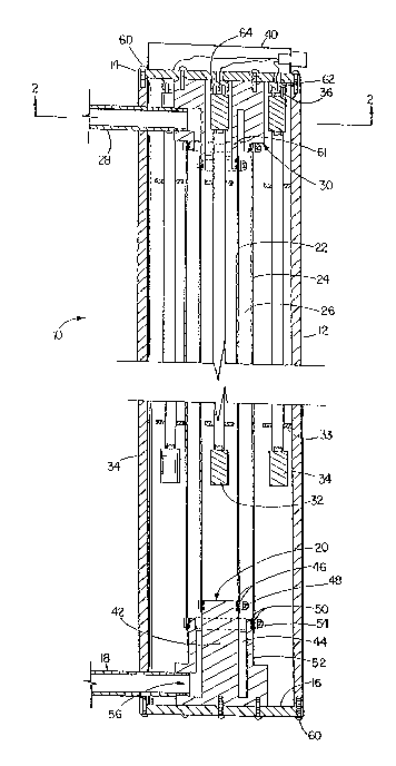
FIG. 1 is a longitudinal section through the
center axis of an ultraviolet disinfecting device
according to the invention; and
FIG. 2 is a transverse section through an
ultraviolet disinfecting device according to the
invention through section 2-2 of FIG. 1.
Referring to FIG. 1 for an overview, an
ultraviolet disinfecting device 10 is made of a
polished
or anodized lame aluminum pipe 12 with covers 14,
16 on
both ends. The fluid medium or the liquid to be
disinfected enters the device through an inlet pipe
18
and travels into the bottom header block 20 which
has
attached two ultraviolet transparent Teflon'" tubes
22,

-3-
24. The fluid flows upwards in the thin annular passage
(annulus) 26 created between the Teflon'" tubes 22, 24
and exits through outlet pipe 28 in the top header block
30. Ultraviolet lamps 32, 34 with connecting pins 36 on
only one end are suspended in the chamber or device 10
from top cover 14; one ultraviolet lamp is placed ins_de
the inner Teflon'" tube 22 while a multiple number o~
ultraviolet lamps 34 are arranged on the outside o. the
outer Te=lon'" tube 24, thus providing radiant enerey
from both sides of annulus 26. Ceramic centering r~rcs
33 are placed at intervals along the ultraviolet lamps
32, 34. An electrical connection box 40 is at~ac'.:e~ ~o
ton cover 14 while the ballasts (not shown) reguire~, fo=
energizing the lamps are mounted in a sepa_at~ ::an
cooled enclosure.
Re'erring to DIGS. 1 and 2, the bottom zeace_
20, made of an aluminum or stainless steel block, is
typically 2.50" in diameter, with a solid central shat
portion 42, 1.00" in diameter and 3.00" high, 0.50"
longer than the rest of the block. Around the central
shaft is a 0.20" wide channel 44 which extends to within
0.25" of the bottom of header 20. Two 0-rings 46 ara
mounted in grooves on the end of shaft 42, and inner
Teflon'" tube 22 is slipped over the O-rings and held
in place by stainless steel hose clamp 48. Outer
Teflon'" tube 24 is slipped over O-rings 50 in grooves
on the outside of the main bottom header portion 52 and
secured in place with hose clamp 54. Inner and outer
Teflon'" tubes 22, 24 create between them annula_~
passa5~e 26 which is 0.40" thick. A 0..5" diameter :n?et
56 provides access to channel 44 in the header block and
is threaded to accept inlet pipe 18.
The outlet or the top header 30 is also made of
a polished aluminum or stainless steel block. Unlike

' I~
- 4 - 60412-2121
the bottom header, the top header central shaft 61 is hollow,
which allows for the insertion of ultraviolet lamp 32. The inner
and outer TeflonTM tubes 22, 24 are attached to the central shaft
and the main portion of the top header in the same manner as
they are to the bottom header.
The top and bottom header blocks 30, 20 are positioned
in the center of their respective end covers 14, 16 and attached
by screws 60. Inside of the top cover 14, lamp holders 62 are
attached by screws at precise locations in such a manner that
attached lamps 34 surround outer TeflonTM tube 24, typically at
22-1/2°, 45°, 90° or 180° intervals. Lamp holder
64, in the
middle of the top cover, receives ultraviolet lamp 32 which is
suspended in the center of inner TeflonTM tube 22. The whole
top cover assembly, with attached ultraviolet lamps, is removable
for lamp replacement.
When the ultraviolet disinfecting device 10 is in
operation, fluid flowing into inlet pipe 18 empties into channel
44 and is forced upward past the edge of bottom header portion
52 and into annular passage 26 between TeflonTM tubes 22, 24.
The natural turbulence within annular passage 26 constantly churns
the thin film of fluid, throwing fluid particles on the walls of
the TeflonTM tubes. The energized outer ultraviolet lamps 34
irradiate the fluid in annular passage 26 from the outside-in,
while the ultraviolet lamp 32 inside the inner TeflonTM tube
irradiates the fluid from the inside-out. As the fluid travels
from the bottom of the unit to the top, -it is disinfected and
r

- 5 - 60412-2121
exits from the top exit pipe 28.
Other embodiments and aspects of the invention will be
apparent to those skilled in the art. For example, instead of
the coaxial arrangement described, two parallel banks of elon-
gated ultraviolet lamps can be arranged to provide between them,
in a sandwich arrangement, a thin passage for flow of the fluid
to be disinfected. Several disinfecting devices can be arranged
in series for additional purification. A wide variety of fluids,
from clear ones such as water to turbid or opaque ones such as
milk, beer, wine or other beverages, or emulsified oil for machine
lubrication, can be disinfected in the device of the invention.
The invention may be used for other radiant energy or photo-
chemical reactions.

Representative Drawing
A single figure which represents the drawing illustrating the invention.
Administrative Status

2024-08-01:As part of the Next Generation Patents (NGP) transition, the Canadian Patents Database (CPD) now contains a more detailed Event History, which replicates the Event Log of our new back-office solution.

Please note that "Inactive:" events refers to events no longer in use in our new back-office solution.

For a clearer understanding of the status of the application/patent presented on this page, the site Disclaimer , as well as the definitions for Patent , Event History , Maintenance Fee  and Payment History  should be consulted.

Event History

Description Date
Inactive: Expired (new Act pat) 2010-11-22
Inactive: Late MF processed 2008-01-04
Letter Sent 2007-11-22
Inactive: Late MF processed 2007-10-05
Letter Sent 2006-11-22
Inactive: Late MF processed 2006-11-01
Inactive: IPC from MCD 2006-03-11
Letter Sent 2005-11-22
Letter Sent 2005-09-15
Inactive: Office letter 2005-04-07
Inactive: Payment - Insufficient fee 2005-04-05
Inactive: Late MF processed 2005-03-15
Inactive: Office letter 2005-03-03
Letter Sent 2004-11-22
Letter Sent 2004-02-20
Inactive: Office letter 2003-01-10
Letter Sent 2002-11-22
Letter Sent 2002-11-15
Grant by Issuance 2002-06-11
Inactive: Cover page published 2002-06-10
Inactive: Entity size changed 2002-04-08
Inactive: Final fee received 2002-03-28
Pre-grant 2002-03-28
Notice of Allowance is Issued 2001-10-01
Letter Sent 2001-10-01
Notice of Allowance is Issued 2001-10-01
Inactive: Approved for allowance (AFA) 2001-09-18
Letter Sent 1999-02-03
Reinstatement Requirements Deemed Compliant for All Abandonment Reasons 1999-01-14
Deemed Abandoned - Failure to Respond to Maintenance Fee Notice 1998-11-23
Letter Sent 1997-09-30
Inactive: Status info is complete as of Log entry date 1997-09-23
Inactive: Application prosecuted on TS as of Log entry date 1997-09-23
All Requirements for Examination Determined Compliant 1997-07-23
Request for Examination Requirements Determined Compliant 1997-07-23
Application Published (Open to Public Inspection) 1991-05-23

Abandonment History

Abandonment Date Reason Reinstatement Date
1998-11-23

Maintenance Fee

The last payment was received on 2001-11-06

Note : If the full payment has not been received on or before the date indicated, a further fee may be required which may be one of the following

  • the reinstatement fee;
  • the late payment fee; or
  • additional fee to reverse deemed expiry.

Patent fees are adjusted on the 1st of January every year. The amounts above are the current amounts if received by December 31 of the current year.
Please refer to the CIPO Patent Fees web page to see all current fee amounts.

Fee History

Fee Type Anniversary Year Due Date Paid Date
Request for examination - small 1997-07-23
MF (application, 7th anniv.) - small 07 1997-11-24 1997-11-13
Reinstatement 1999-01-14
MF (application, 8th anniv.) - small 08 1998-11-23 1999-01-14
MF (application, 9th anniv.) - small 09 1999-11-22 1999-11-03
MF (application, 10th anniv.) - small 10 2000-11-22 2000-11-14
MF (application, 11th anniv.) - small 11 2001-11-22 2001-11-06
Final fee - standard 2002-03-28
MF (patent, 12th anniv.) - standard 2002-11-22 2002-10-31
Reversal of deemed expiry 2007-11-22 2003-11-20
MF (patent, 14th anniv.) - standard 2004-11-22 2003-11-20
MF (patent, 13th anniv.) - standard 2003-11-24 2003-11-20
MF (patent, 15th anniv.) - standard 2005-11-22 2006-11-01
Reversal of deemed expiry 2007-11-22 2006-11-01
Reversal of deemed expiry 2007-11-22 2007-10-05
MF (patent, 16th anniv.) - standard 2006-11-22 2007-10-05
MF (patent, 17th anniv.) - standard 2007-11-22 2008-01-04
Reversal of deemed expiry 2007-11-22 2008-01-04
MF (patent, 18th anniv.) - standard 2008-11-24 2008-11-05
MF (patent, 19th anniv.) - standard 2009-11-23 2009-10-14
Owners on Record

Note: Records showing the ownership history in alphabetical order.

Current Owners on Record
MAKHAN M. JHAWAR
Past Owners on Record
EUGENE N. SHORT
Past Owners that do not appear in the "Owners on Record" listing will appear in other documentation within the application.
Documents

To view selected files, please enter reCAPTCHA code :


To view images, click a link in the Document Description column (Temporarily unavailable). To download the documents, select one or more checkboxes in the first column and then click the "Download Selected in PDF format (Zip Archive)" or the "Download Selected as Single PDF" button.

List of published and non-published patent-specific documents on the CPD .

If you have any difficulty accessing content, you can call the Client Service Centre at 1-866-997-1936 or send them an e-mail at CIPO Client Service Centre.

({010=All Documents, 020=As Filed, 030=As Open to Public Inspection, 040=At Issuance, 050=Examination, 060=Incoming Correspondence, 070=Miscellaneous, 080=Outgoing Correspondence, 090=Payment})


Document
Description 
Date
(yyyy-mm-dd) 
Number of pages   Size of Image (KB) 
Abstract 1993-11-02 1 22
Claims 1993-11-02 2 53
Drawings 1993-11-02 2 41
Description 1993-11-02 6 184
Representative drawing 1999-07-04 1 28
Reminder - Request for Examination 1997-07-21 1 117
Acknowledgement of Request for Examination 1997-09-29 1 178
Courtesy - Abandonment Letter (Maintenance Fee) 1998-12-20 1 184
Notice of Reinstatement 1999-02-02 1 170
Commissioner's Notice - Application Found Allowable 2001-09-30 1 166
Maintenance Fee Notice 2002-12-22 1 173
Maintenance Fee Notice 2005-01-16 1 173
Late Payment Acknowledgement 2005-04-04 1 165
Maintenance Fee Notice 2006-01-16 1 172
Late Payment Acknowledgement 2006-11-08 1 166
Maintenance Fee Notice 2007-01-09 1 171
Late Payment Acknowledgement 2008-01-23 1 167
Late Payment Acknowledgement 2007-10-25 1 164
Maintenance Fee Notice 2008-01-02 1 173
Correspondence 2003-01-09 1 9
Correspondence 2002-12-23 2 86
Correspondence 2002-03-27 1 45
Correspondence 2002-11-14 1 8
Correspondence 2004-02-19 1 16
Fees 2000-11-13 1 41
Correspondence 2005-03-02 2 24
Correspondence 2005-04-06 1 16
Fees 2005-03-14 1 41
Correspondence 2005-09-14 1 12
Fees 2005-09-08 3 79
Fees 2006-10-31 1 30
Fees 1994-10-30 1 73
Fees 1992-10-26 2 80
Fees 1995-10-19 1 83
Fees 1996-10-29 1 83
Fees 1993-10-14 1 56