Note: Descriptions are shown in the official language in which they were submitted.
2~~~~~~
.'1.~.ll.s~'! I r3nSlr'3 tl.on !7f _~ rt~?r'~8 ti C~al ~ t°~'G
~DDl.lCatiOn
NCT/AT 90/00030
TA9LET ~%I.°°=~'~~=
This invention r=_letes tc a tablet dispenser
comnrisinn a tubular protective nousinn, ~uhich in a guide
ahaft is provided with longitudinal trac;<s for tablets, ~:mich
r_an ba inserted in the 'or~~ of a columnlike stack, and ~uit'~
a pressure-loaded ram for one °nd o' tha stac'< of tablets,
~nhic'~ ram °=eds the tablets alone the lpnnitudinal tracks to
an a jeCtOr) !~lfllC~'1 enClafaeS t''!? StaC'< ad ~~BC°'!t t0 1. t5 _
Ott'ier
and by n!hich tha tablets, !nhich are guided between lateral
nuines adjacent to the eiector, can in~ividuallv b° dis-
placed transversely to the ianoitudinal direction of the Stack.
such tabl°_t ~'ispensers are preferably used 'nr
tablets n!hich can easily 5e assembler in a columnlike stack,
such as tahlets havinn a orisTatic or cylindrical periphery.
main field of application of the tablet disAenser see re_
freshinn tablets and lozennes !nhic~ !~a~~e basically the shape
of a rectannular prism and contact each other on their flat
sides in the stac'<.
In knonn tablet nisnensers the lonnitu~inal
tracks for the stack of tabla_ts are for~~ed in a separate
dra!ner, which at its end that protrudes out of the orot?ctive
housinr7 carries the ejector) and the drawer is coen only en
that side to which the tablets are aus!~ec~ out so that the stack
of tablets can ;~e in9erte!~ fr~~~ thet side when the ~!ramer has
Seen pulled o~.~t. The ram, mhic!~ in that case is lonnitudinallv
slidahlv nuided in the drawer anr~ in the housinn, is supported
et the inner ~~nr~ of the rira!aer by Teans of a compression sprinn,
which is accommodates within the tablet-nuidinn shaft. ~s the
=-~otv ~!ra~aer is null=_~ nu+., that ram encases Latent means
oravir'er~ art jacent to the ooeni~'~n of the tube ooenino of the.
protective housino and saih ~'et2nt ~~eans arevent a Further
oullino out nr cushion out of the ram. The ~!rau~er must be
extractable at I:east by the lennth pf the stack. ~ec~ar~!less
Of !~:hgth2r Or nOt th5 ~'T9!~!er 1.5 ' 11 le!~, tha COmpre5510n
sorino tends to null the ~!ra!aer into the protective housino
as far as to a stop and thus performs a dual function, be-
cause !dhen the drawer has Seen nushsc~ in the compression
sprinn !hill advance the ram and the stac',< of tablets by the
heioht of a tablet whenever 2 ;abl~t has been taken.
The known tablet ~!isaenser has various disad-
vantaoes. 4bove all, it is necessary to use relatively ex-
pensive sorinos !dhich are of intricate shape in dispensers
For rectanoular prismatic tablets may consist of coil sorinos
havinn convolutions contactinn extending alone the periphery
of a prism, anr~ in assembling it is necessary to assemble the
three harts consisting of the protective housinn, drawer and
option in exactly predetermin=c~ positions and to insert the
ram bela!n the !ietent means of the protective housing. purinn
a part of that assemblino at least a part of the spring is
orestressed bet!neen the action and the dra~ner so that care-
lessness may have the r~_sult that the carts nreviouslV con-
tacta~l !pith each other !pill be forced apart. ~ssemblinn can
be effected only by hand rather than by automatic apparatuses.
Nlost tablet dispensers of the aresent 'kind are ~tefinitely
mas9-produced articles so that the assembling costs gave pre-
viously constituted a lame snare of the total costs. The
spring mhich is provider! is not anly expensive in its manufac-
ture but has ariditional _hecisiva ~isadvantapes. The sprinn
has a relatively hinh initial stress mhan the hrawer has been
pulled out. Faults in the manuFacture of tha tablet dispenser,
normal !.near in use pr arbitrpry hamane may have 'the result
~~'~~~~~
_Z_
that the ejsctor ram is no lonoer satisfactorily held by the
detent means at the tube and of the protective housing but
mill iumo out ~~hen the r;'ra~~er has been pull ed out so that
the stack is than thrown gut and the snrin~ also jumps out
algnn an uncontrollable path. such a sprinn jumginn out may
inflict injuries mainly to t'~2 face ?nd eyes and far this
reason the previous tablet dispensers are objectionable also
n~~inn to that dapper and to product liability.
In most cases it is usual to supply ,:rv_ stack
of tablets in separate gac'canes and to fill the tablat dis-
penser !with the stack of tablets mhich has been taken from
the sac!<aqe anr~ in some cases oven with individual tablets
~,~hich are consecutively supplied. That procedure is expensive
and because the stack or individual tablets must be nrasped
it is unhygienic. qesides, the stack aft=_n fells apart as it
is transferred from the nac~anp into the taolet nisoenser
and in that case must be r~-ordered.
It is an object of the invention to provide a
tablet dispenser which is pf the '.'.<ind describeri first herein-
befar2 and which can b2 manufactured and assembled more simply
than the known tablet dispensers and has a reliability in
operation and above all reliably prevents an uncontrolled
jumping out of the ram anc~ the snrinn. G partial object of
the invention is to nravic!e a tablet dispenser which can be
supplied pith the tablets nuicklv and satisfactorily From a
hygienic aspect.
The main abject set forth is ~caomolisheri in
that the spring biasinn the ram is accommodated in the housinn
in a sprinn shaft, which is disposed besi~!e 'the shaft far
nuidinn and accommor~atinn the tablets, and the spring biases
a ~7uidinq memher) idhich is nuided .in the sorinn shaft and which
carries the ram pn an arm) a carrying ring or a bracket) which
extends out through a lonnituriinal slot throunh nhich the two
shafts communicate with each other.
-
In the ~!esian in accordance !dith the invention
the spring _is accommoriatec! in = oroteots~ arrannement and
may have a simple shape, !~W ich can easiiv h? manufactured.
The spring together !pith the nuidinn ~e~ber and the ram
can separately be assembled «hen the s~rinn is suhstantiallv
relaxed so that that assembling ~.!i11 involve nc difficulties
and can be eerformed in automatic asoaratuses. Contrary to
the knomn hesign the ram need net occupy the entire cross-
section For guiding the tablets sa that there is no risk that
abraded matter and other taolet residues gay adversely affect
the proper functions of the ram and the sorin~.
In a preferred embodiment the spring shaft is
closed at the ejection end of tha noosing and at its opposite
end has an openinn !>>hich can be closest and serves to receive
the guiding !ember and the spring) and the quidina slot is
preferably open to that receivinn opening so that the ram can
be made tn be intenral !pith the arm anrt the puidinp member and
can be inserted jointly pith the sorinn. ~ permanent, reliable
closure may ba r.~rovirleri for the receivinn nneninc~ and may con-
sist) inter alia) of inseparably inserted glues or of sealants
or the rims of the opening may be pressed after the assemblinn
or such measures ray be adootec! in combination.
In accordance ~~it"~ a further preferred feature
'the tablet dispenser is associatert mith a magazine) which pre-
ferably constitutes a part of a tablet oackape and is pro-
vided n.!ith the tablet tracks and is adaote~i to be replaceably
inserted into the tablet-c~uidinq shaft of the housinn and at
least at one enrl of its lenr~th has a passage opening For the
ram anri at least at the other en~i of its length has lateral
ooenincs for receivinn the ejector ant for the ejection of the
tablets an!1 in that lonniturfinal side mhich faces the spring
shaft in the inserted position is nrovi~ied !pith a slot, which
is aliened naith the communicative longitudinal slot and serves
to receive the arm nhich carries the ram.
Like openings are preferably arovided at both
ends of the maoazine so that the magazine can selectively
be inserted with one snd or the other facino the ejection end.
The magazine may consist of a elastic -pldina or of a relati-
velv thick metal foil or the li'<e sp that only ipw costs are
incurred in mass ororiuction. If the ~ar~azins constitutes also
a part of the oackar7e, the other packaoe casts will 5e lower
than those of oackapes of the previous kinr!. The insertion
of the manazine is much simpler than the introduction of a
stack of tablets and the tahl2ts thar~selves need not be
orasped durinn the insertion and other Taninulation so that
the manipulation is Tech more hynienic than before.
In order to insure a satisfactory longitudinal
guidance of the tablets for the ejecting operation, an embo-
diment is preferred in which the tablet tracks of the maga-
zine consist of longitudinal knife blades or combs) which are
provided on and protrude from the inside of the malls of the
magazine. The inner edqe9 Of the combs or ''<nife blades, which
protrude into the interior of the magazine housing, may be
provided on at Least two mutually opposite sides of the ma-
gazine within the contour line of the tablets so that combs
or knives mill form quidinn grooves into the tablets of the
inserted stack pf tablets at least as the tablets are dis-
placed to the ejector so that a more reliable guidance is
achieved. A tiltino of the tablets in the stack ~.~ill reliably
he prevented in any case even if the ram acts on the lowermost
tablet only tin a small contact surface.
The magazine arnferablu comprises ~ualls ~ohich
are resiliently deFormable as ~he tablets are inserted be-
tween the edges disposed insid= the contour of the tablets.
(~lith that design, the magazine can b~ Filled with the tablets
through a lateral opening, which substitutes one longitudinal
mall and while the combs or knives resilient enqane the tab-
lets and retain the tablets anr! in transit hold the tablets
against dislocation and against falling out thrpugh the re-
ceiving ooeninc~.
Further structural features of the tablet dis-
penser 'nay be adopted from various aspects. In a possible
embodiment the nanazine can be inserted into the protective
housing from the ejection end of the housing and the ejector
is attached to the housing itself and for the inserting opera-
tion can be s~~ung away, e.p.) like a flap, from the corres-
ponding pneninn, and the ejector is locked by detent means in
its operative position. In a Miff=_rent embodiment the housing
has a lateral opening for r=ceivinn the magazine and during
the in3ertipn of the magazine the ram is retracted to such an
extent by means of handles acting an the ruiding member and/or
the sprinn that the ram can be engaged with that end of the
stack ~.~hich faces away from the =jector. In that case a back
member of the magazine may close the lateral housing opening
and, e.q., may supplement the housing to form a handle.
In accordance with a further feature of the tab-
let dispenser in accordance «ith the invention the stack of
tablets is accommodated in a manner known per se in a drawer,
which is adapted to be pulled out as far as to a stop from
the end of the protective housinn and carries the ejector at
that end which protrudes from the housing when the drawer has
been inserted, the drawer has a lateral opening for receiving
the stack of tablets and/or the manazine and a slot far nuid-
inq the ram arm) and the drawer is adapted to be fixed in its
inserted position by a releasa5l~ braking catch. In that em-
bodiment the tablets or the stack of tablets or the magazine
can be inserteri in the customary manner when the ~iramer has
been pulled out of the protective housing. because the drawer
is no longer acted upon by the spring, it need not be held in
its pulled-out position so that the tablets can be inserted
more simply. ~!evertheless the drawer is locked in its pushed-
in position by the brakinn catch. The restraining force of
that hrakinn catch must somewhat exceed the farce nhich is
2
_,_
exerted by the sorina via the ram to the stac!< of tablets
to push out that stack. In spite aF the use of that drawer,
there is no risk that an actuation of that drawer may cause
the spring or the ram to b2 released and/or thrown out.
In a preferred =~~bodinent of that last-men-
tioned desi,pn the braking catch consists of a resilient brak-
inn tonnue, which is provided and/or integrally formed ad-
jacent to that end of the ~'rawar ~!hich can be inserted into
the housing and said tongue particularly constitutes a part
of a drawer end wall provided at that end and with its free
end applies pressure to that wall portion of the housing which
is opposite to the receivine slot) said tongue is arched as
it thus applies pressure, and like an avercenter spring
assumes a bent position protruding into the drawer as the
riralner is inserted and as the drawer is pulled out is rever-
sely bent beyond the dead center to a braking position pro-
trudinn outwardly aver the drawer. That embodiment of the
brakinn catch is particularly sir!ole and in the preferred
embodiment the tongue can be Formed iointly !with the drawer
if the drawer is made of a suitably material. The design can
Further be simplified if the ram and/or its carrying arm when
Fully extended protrudes with its underside out of the hous-
inn at least to the extent of the spring excursion of the
spring tongue, a!hich has integrally been formed with the end
wall of the drawer and has only a limited flexibility, so that
the end wall of the drawer and the spring tonr~ue which down-
wardly protrudes beyond the drawer (an~i assumes that position
as the drawer is pulled out of the housinn) constitute catches
which limit the extraction of the ~trawer.
Further details and arvantaoes of the subject
matter of the invention mill becpme apparent From the Following
cescription of the drawinn.
~'~g
The subject matter cf the invention is illus-
trated by may/ of axample in the drauinQ, i n nhich
Finure 1 shows a tablet dispenser which is in
accordance with the invention and is shown pith an inserted
stack of tablets in position for use; the arotective housine,
a drawer provided here am a magazine for the stack of tablets
are sho~~n in longitudinal section anr'. the contours of a tablet
ejector attached to the drawer are shown in phantom;
Figure ~ is a corr~saondino lonnitudinal sec-
tional vietn sho~~ina the housino mith the drawer pulled out
hefore a magazine is inserted;
Figure 3 is a sectional view taken on line III-
III in Finure 1;
Figure ~f is a front elevation sho~iinq the maga-
zine provided in accordance «ith Finuras 1 and 3;
Fie~ure 5 is a longitudinal secitonal view show-
ing the magazine;
Figure 5 is an elevation showing the magazine
of Figure 5 viewed from the right; and
Figure 7 is a sectional vie~~ taken on line VII-
IIII in Fic7ure 5.
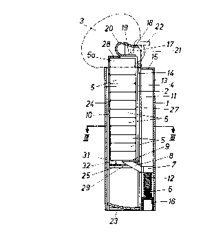
The illustrated tablet dispenser consists of a
protective housinn 1, a drawer ? arovi~ied with an ejector 3)
the contours of which ara shown in phantom) a magazine 4, which
can be inserted into the drawer ? and contains a stack of in-
dividual tablets 5 (pat sho~in in Figures ~ and 3) a spring S,
a quidinr~ member 7 and a ram 9) which is connected to that
yuidinn member bV an arm o.
The protective hpusinp 1 cpmorises a tablet- cr
drawer-nui!iinn chart lig, Which extends throughout the length
of the housinc, and b2si~'2 that abaft comprises a sheft 11
for guiding the sprinn o and the Gui~'iro -ember 7, Which has
a core pin 1~ ~~xtandinn into the sorinn) ~.ohich consists of
a cylindrical tail spring ... The shafta 1C and 11 communicate
with each other through a sict 13 fcr nuidina the arm 8. The
drawer 2 has a slot 14, which i s alir;ned !pith the slot 13.
The spring-aui~'ino shaft 11 is closed at its
top by a .top wall portion 15. after the Guiding member 7) the
arm ~ With the ram 9, and the sarina ~ have been inserted, the
sorinc~-guiding shaft 11 is permanently closed by an insert 16.
l?s has been mentioned the back of the drawer 2
is farmed with the slot 14. The front side of the drawer ~ is
shown on the left in Figure 1 and is open so that the magazine
4 can be inserted. The Far~aard and rear side walls of the
draper ? are extended 'to provide bearing brackets 17 for the
ejector 3, which is pivoted to said bearing brackets on a
transverse pivot 10. Enri ~uall exten ions 19 of the drawer 2
constitute a too stop for the manazine. qs a continuation in
length of said °-n~i mall extensions a loaf spring 2.C, Which is
made of plastic, is attached and serves as a restorinn coring
for the ejector 3, Which has an sjector claw ?.1 For pushing
out the presently uppermost tablet 5a transversely to the .
lonnitudinal direction of the stack when the ejector is pivo-
tally moved by means of an ~ctuatinn handy 22.
The drawer -'. contains a suppprtinq partition 25
For supporting the magazine at its bottom end. I~t the bottom
end of the drawer, a drawer end ,hall is provided) i.~hich is
intenrally formed with o spring tonnue ~3, Which extends into
a trough-shaped recess ~4 in the Front Bide of the housing
an~i under a resilient initial stress applies pressure to that
_ 1 GI _
wall portion of the recess 24 which is aooosits to the slot
13. As the drawer is slidably inseried, t~~ saring tongue ?3
assures the position shown in =icure 1. %~s the drawer ? is
pulled out, the spring tongue ?3 swinns to the position shown
in Figure ?. In that culled-out aosition the associated drawer
bottom provided with the sprine tanoue ?3 annaoes the ram 9
and/or the arm ti to constitute a lack that prevents the drawer
from bainp pulled nut. nut !hen the 'rawer has been swung to
the right f,Fir~ure ?) the ~trauer can 5e pushed so that the slot
14 receives the arm ~ and !dhen the tonpus ?3 is in the swung
position shown in Figure 1 the r!r?wer can be hunn into the
housinn 1. !~Ihen the drawer ? has shortly Seen inserted and
retracted the tpnnue ?3 will s!~inn back to its locking position
shown in Figure ?. In that case the drawer 2 can b2 demounted
only in that the snrinc tonnue ?3 is tilted from below to its
other smunq oosition by means of an imnlament which is inserted
into the shaft 10.
The manazine 4 shown in Finures 1, 3 and 4 com-
prises a rear mall 26, which has a slot 27 that is aligned
with the slots 13 and 14, end walls 2q having equal and opposite
openings ?.9 for recnivino the carrying ~oall E and the ram 9
and side walls 3C) a~hich on their inside surfaces facing the
stack pf tablets carry rtuide ri5s 31) 32. The stack of tablets
can be inserted mhile the ~~alls 30 are resiliently spread
apart. The ribs 32 will then snap in behind the inserted tab-
lets anrJ the ribs 'i1 constitute knifa blades) ~nhich cut e7uid-
inn rarpaves into the tablets ~urinq their longitudinal dis-
placement. The ejector claw ?1 pan be inserted through the
slot 27. The uppermost tab.lst 5a is ajectsr! to the left ~ahila
the ribs 3? are forced apart.
nln that ~idp which Pads the TP_CP3S ?4 the ma-
nazine ~ta shown in Finures 5 end 7 comprises a longitudinal
wall 33) mhich at its top and ~ottom leaves mindows 34 open
~~~ ~'~
- 11 -
for the ~jection of the taGlets 3. Dn the ether hand the
slot ~7 has peen omitted as hell as the rear call ~5 and the
side walls 3C are provided with the rigs 31, 32 in an arran-
gement which is ecual and opposite to that of the magazine 4
shown in Figures 1, ~ any! 4. In that case the ribs 32 serve
only to retain the taolets after they ~av= been inserted into
the magazine and the tablets are =_jecte~' through that window
34 Which in a given case is adjaceni tg the ejector.
The manazines '+, 4a constitute a package far
the stack of tablats and must b~ prgvipd only with a simple
mraager for sale or shipment.