Note: Descriptions are shown in the official language in which they were submitted.
2~3~
--1--
BACKGROUND OF THE INVENTION
This invention relates to down-hole probe
assemblies for use in conditions of high vibration or
shock, such as are encountered within the bottomhole
assembly of a rotating drill string during drilling.
During downhole measurement-while-drilling (MWD)
one or more measurement probes are located inside the
drill collar portion of the drill string close to the
drill bit, and there is a risk that such measurement
probes will suffer damage or that the measurements taken
will be compromised by the high levels of vibration or
shock to which the probes are subjected in use.
One form of probe which is used is the gamma ray
detector probe which detects the gamma radiation received
from radioactive elements in the formations penetrated by
the borehole being drilled, ~or the purpose of producing a
ga~ma ray log against depth for use in formation analysis.
Such gamma ray detector probes generally comprise a
scintillation counter having a gamma ray scintillator
crystal and a photomultiplier tube joined at an optical
interface formed, for example, of silicone grease. The
integrity o~ the optical interface between the crystal and
the photomultiplier tube can be affected by vibrations and
this can seriously compromise the performance of the
scintillation counter.
It is an object o~ the invention to improve the
mounting of a scintillation counter or other vibration-
sensitive inner unit of a downhole probe assembly so as
,
2~3~L080
--2--
to protect the unit against the effects of vibration.
SUMMARY OF THE INVENTION
According to the present invention there is
provided a downhole probe assembly for use in conditions
of high vibration or shock, comprising a vibration-
sensitive inner unit having a cylindrical outer surface,
an outer casing having a cylindrical inner surface within
which the inner unit is accommodated, and an intermediate
vibration-damping composite sleeve extending between said
inner and outer surfaces and having two coaxial sleeve
parts fitting one within the other and consisting of an
apertured sleeve part made of relatively rigid material
and a further sleeve part made of relatively resilient
material having portions which extend through apertures in
the apertured sleeve part, whereby portions of the further
sleeve part engage said inner surface and further portions
of the further sleeve part engage said outer surface so as
to support the inner unit within the outer casing.
Preferably the further sleeve part fits within
the apertured sleeve part so that inner portions of the
further sleeve part engage the outer surface of the inner
unit and outer portions of the further sleeve part extend
through apertures in the apertured sleeve part and engage
the inner surface of the outer casing.
In a preferred embodiment the apertured sleeve
part has a cylindrical wall having a plurality of axial
slots therethrough regularly spaced about the
circum~erence of the wall, and the further sleeve part
2 0 3 ~
has a generally cylindrical wall having axial ribs which
extend through said slots.
In this regard the sleeve will usually be of
generally circular cross-section, although sleeves of
other cross-sections, such as hexagonal, triangular or
square, are also contemplated within the scope of the
invention, particularly where the inner and outer
cylindrical sur~aces of the outer casing and the inner
unit have cross-sections which are other than circular.
Furthermora the further sleeve part may have
portions of its wall which are bowed in cross-section to
form said axial ribs, and may have elongate recesses in
portions Df its wall intermediate said axial ribs such
that the edges of the recesses engage facing wall portions
1~ of said apertured sleeve part. Also the further sleeve
part may be made of elastomeric material. These features
enhance the ability of the further sleeve part to damp
external vibrations whilst allowing for thermal expansion
of the further sleeve part.
In addition the inner unit may be subjected to
axial loading at its ends by end caps at the ends of the
sleeve.
Furthermore the sleeve may be resiliently
supported within the outer casing by biasing means acting
axially between each end of the sleeve and a respective
adjacent end wall of the outer casing.
The end caps may be provided with axial
extensions which extend into axial bores in the end walls
2 ~
--4--
of the outer casing for guiding the ends o~ the sleeve,
and the biasing means may be constituted by compression
springs surrounding said axial extensions. At least one
of the end caps may also be formed with a bore for
electrical leads passing to the inner unit.
In one application the inner unit comprises a
cylindrical gamma ray scintillator crystal and a
cylindrical photomultiplier tube placed end to end with
their adjacent ends separated ~y an elastomeric optical
interface member. The mounting arrangement provides both
lateral and axial isolation from external vibration of the
inner unit, and particularly of the sensitive optical
interface member.
BRIEF DESCRIPTION OF THE DRAWINGS
In order that the invention may be more fully
understood, a preferred embodiment of the invention will
now be described, by way of example, with reference to the
accompanying drawings, in which:
Figure 1 is a section through two end portions
of a downhole probe assembly incorporating a gamma ray
detector;
Figure 2 is a side view o~ the vibration-damping
sleeve of the assembly accommodating the dete~tor;
Figure 3 is an axial section taken along the
line III-III in Figure 2; and
Figure 4 is a cross-section taken along the line
IV-IV in Figure 2.
2 ~
DETAILED DESCRIPTION OF THE_ DRAWINGS
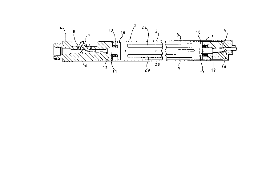
Referxing to Figure 1 the probe 1 has an outer
casing 2 having a cylindrical wall 3 extending between an
interconnection bulkhead 4 and an electromagnetic shield
body 5. The interconnection bulkhead 4 has an axial bore
6 into which electrical leads 7 extend through a side
opening 8. The outer casing 2 accommodates a vibration-
sensitive inner unit within a vibration-damping composite
sleeve ~ having end caps 10 provided with axial extensions
11 which are received within cylindrical recesses 12
respectiv~ly in the interconnection bulkhead 4 and the
shield body 5. The axial extensions 11 are surrounded by
compression springs 13 whose function will be described
below.
Figure 2 shows the vibration-damping composite
sleeve 9, within which the inner unit is accommodated,
removed from the outer casing 2. Furthermcre Figure 3,
which is a section along the line III-III in Figure 2,
shows the inner unit 14 having a cylindrical outer surface
surrounded by the sleeve 9 and consisting of a cylindrical
sodium iodide scintillator crystal 15 and a cylindrical
photomultiplier tube 16 placed end to end with their
adjacent ends separated by an isolating optical interface
in the form of a silicone rubber disc 17.
The components 15, 16 and 17 of the inner unit
14 are preloaded axially between the end caps 10 with the
interposition of shims 18 of the required thickness, the
` 2a3:~0~0
rubber disc 17 providing some resilience in the mounting
of these component~. Furthermore the end caps 10 are held
fixedly and sealingly on the ends o the sleeve 9 in known
manner and are provided with axial bores 19 for the
passage of electrical leads. In addition branch bores 20
are provided in the end caps 10 for a purpose which will
be apparent from the following description. A solder
bucket 21 extends through the shims 18 and is provided for
the connection of wiring to the crystal 15.
Referring to Figure 4, the vibration-damping
composite sleeve 9 shown therein in cross-section
comprises an apertured metal sleeve part 25 and an
elastomeric sleeve part 26 made, for example, of rubber.
The metal sleeve part 25 is formed with five axial slots
27, and also two further axial slots 28 which are providsd
for the passage o~ wiring extending between the axial
bores 19 of the end caps 10 by way of the branch bores 20.
As may be seen in Figure 4, the five axial slots
27 are regularly spaced about the circumference of the
cylindrical wall of the metal sleeve part 25, and are
provided for receiving corresponding axial ribs 29
provided on the generally cylindrical elastomeric sleeve
part 26. The axial ribs 29 are formed by outwardly bowed
portions 30 of the wall of the elastomeric sleeve part 26
which project through the axial slots 27 so as to engage
the inner cylindrical sur~ace of the outer casing wall 3
when the composite sleeve 9 is fitted within the outer
casing 2.
2~3~
Furthermore the elastomeric sleeve part 26 is
formed with five elongate recesses 31 in the portions of
the sleeve part wall intermediate the axial ribs 29 such
that the recesses 31 face the inside wall of the metal
sleeve part 25 and such that the edges 32 of the recesses
31 engage the facing wall portions of the metal sleeve
part 25. The bowed walled portions 30 of the elastomeric
sleeve part 26 also form axial grooves 33 in the inside
surface of the sleeve part 26 and define between the
grooves 33 axial lands 34 for engaging the outer
cylindrical surface of the inner unit 14.
Thus the vibration-damping sleeve 9 provides
lateral isolation of the inner unit 14 with respect to
external vibration applied to the outer casing 2 by virtue
of the fact that the axial lands 34 of the elastomeric
sleeve part 26 engage the outer surface of the inner unit
14 and the axial ribs 29 of the sleeve part 26 engage the
inner surface of the outer casing 2. The form of the
: elastomeric sleeve part 26 is such as to enhance the
ability of the sleeve 9 to damp external vibrations whilst
allowing for thermal expansion o~ the sleeve part 26 under
the effect of the high temperatures encountered down-hole.
Furthermore the metal sleeve part 25 serves to maintain
the structural form of the elastomeric sleeve part 26
whilst in no way prejudicing the vibration-damping
properties of the composite sleeve 9.
Various modifications of the form of the
vibration-damping composite sleeve 9 are cont~mplated
`` 2~3~
within the scop~ of the invention. For example the number
and the axial extent of the axial ribs 29 may be varied.
Also the metal sleeve part may be inside the elastomeric
sleeve part in which case provision would be made for
portions of the elastomeric sleeve part to project
inwardly through slots in the metal sleeve part.
As previously mentioned axial slots 28 are
provided in the metal sleeve part 25 for the passage of
wiring, indicated at 35 in Figure 4. As may be seen in
Figure 1 an axial bore 36 is provided in the shield body 5
for the passage of such wiring, and wiring from the
photomultiplier tube, to associated processing electronic
circuitry (not chown).
In addition, axial isolation of the inner unit
14 with respect to vibrations applied to the outer casing
2 is provided by virtue of the fact that the axial
extensions 11 of the end caps 10 are a loose fit within
the recesses 12, and by virtue of the compression springs
13 acting between the interconnection bulkhead ~ and the
end cap 10 at one end o~ the inner unit 14 and between the
shield body 5 and the end cap 10 at the other end of the
inner unit 14. The combination of lateral and axial
isolation ~rom vibration ensures that the inner unit 14,
and the particularly the sensitive optical interface
between the crystal 15 and the photomultiplier tube 16, is
well protected from the effects of external vibration.
Finally it is envisaged that a similar vibration
damping arrangement to that described above may be used to
2~
- 9 -
protect other types o~ inner unit, such as Geiger-Muller
counters and other forms of downhole measurement
transducer, as well as sensitive electronic circuitry.