Language selection

Search

Patent 2031284 Summary

Third-party information liability

Some of the information on this Web page has been provided by external sources. The Government of Canada is not responsible for the accuracy, reliability or currency of the information supplied by external sources. Users wishing to rely upon this information should consult directly with the source of the information. Content provided by external sources is not subject to official languages, privacy and accessibility requirements.

Claims and Abstract availability

Any discrepancies in the text and image of the Claims and Abstract are due to differing posting times. Text of the Claims and Abstract are posted:

  • At the time the application is open to public inspection;
  • At the time of issue of the patent (grant).
(12) Patent Application: (11) CA 2031284
(54) English Title: CHAIR BACK SEAT CONSTRUCTION
(54) French Title: METHODE DE CONSTRUCTION DE DOSSIER DE CHAISE
Status: Deemed Abandoned and Beyond the Period of Reinstatement - Pending Response to Notice of Disregarded Communication
Bibliographic Data
(51) International Patent Classification (IPC):
  • A47C 7/02 (2006.01)
  • A47C 4/02 (2006.01)
  • A47C 7/42 (2006.01)
(72) Inventors :
  • MCDONALD, WILLIAM (United States of America)
  • MCDONALD, WILLIAM (United States of America)
(73) Owners :
  • SYSTEMS FURNITURE COMPANY
  • VOGEL PETERSON FURNITURE COMPANY
(71) Applicants :
(74) Agent: OSLER, HOSKIN & HARCOURT LLP
(74) Associate agent:
(45) Issued:
(22) Filed Date: 1990-11-30
(41) Open to Public Inspection: 1991-05-31
Availability of licence: N/A
Dedicated to the Public: N/A
(25) Language of filing: English

Patent Cooperation Treaty (PCT): No

(30) Application Priority Data:
Application No. Country/Territory Date
07/443,525 (United States of America) 1989-11-30

Abstracts

English Abstract


Abstract
A chair which can be shipped in at least two
pieces including the back and the remainder of the chair.
The back has attached to it a curved prong which is
insertable in a curved channel in the remainder of the
chair. The prong and channel are shaped and proportioned
so that they can be readily assembled. Latch means hold
the seat and back together after prong insertion.


Claims

Note: Claims are shown in the official language in which they were submitted.

-4-
The embodiments of the invention in which an exclusive
property or privilege is claimed are defined as follows:
1. In a chair supportable on a surface having a
seat and a back portion which is readily assembled and
disassembled from the seat comprising
a. a curved prong secured to a removable
back portion;
b. a curved channel mounted on the seat
and sized and shaped so that the curved
prong can be readily inserted therein;
and
c. latch means on the seat and back for
holding the seat and back together
after prong insertion.
2. The chair of claim 1 in which the curved
prong has dual curves.
3. The chair of claim 1 in which the chair has
a pair of prongs and a pair of channels.

Description

Note: Descriptions are shown in the official language in which they were submitted.


2 ~
CHAIR BAC SEAT CONST~UCTION
Backqround o~ the Inventlon
! Seating devices having parts readily assembled
after shipment have been proposed (U. S. Patents Nos.
5488,095; 2,625,988; 2,842,1~6; 2,955,641; and 3,990,745).
Chairs with back uprights having rectangular
openings to receive flattened ends of the chair frame have
been disclosPd (U. S. Patent No. 2,281,902) but none of the
10 prior art arrangements have been satisfactory for ease and
reliability of attachment, particularly for chairs that are
often picked up and moved to new locations.
': '
Summary of the Invention
Broadly, the present invention comprises a chair
assembly having a seat portion and back portion in which
the upper chair back carries at least one curved prong
which is placed in a curved walled channel located in the
lower chair back. The prong and channel are shaped and
~ curved so that the prong must be oriented to a position in
which the upper chair back is acutely angled to the
horizontal in order to accomplish insertion. During
insertion the back is rotated to its vertical position. A
latch secures the seat and back portions together. When
the chair is lifted upwardly by its back the prong engages
the walls of the channel and will not come out.
~ t is a feature of the assembly that the prong
does not closely fit in the slots thus making production
tolerances easier to meet thus reducing cost and assembly
time.
. . .
` ~ i ' ' ' . . . : ' '
, .. . '' '. ' - ~
:.; , , . , :. . ~ .
,. .: . .. .
. .

2~
Brief~ esczlp~-on of the Drawinqs
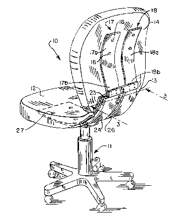
Fig. 1 is a perspective view o~ the assembled
chair with plastic backing removedi
!
Fig. 2 is a side elevational view of the
assembled chair and also showing the orientation of the
upper back just prior to assembly (dashed lines);
Fig. 3 is a sectional line along line 3-3 of
Fig. 1;
' 10
Fig. 4 is a partial side elevational view of a
prong in a channel; and
Fig. S is an exploded partial view showing a
15 releasable engagement clip.
Description of the Preferred Embodiment
In Figs. 1-4, chair 10 includes pedestal 11,
seat 12, removable lower back portion 13 and upper back
20 portion 14. Fastened with screws 16 to upper back portion
14, are curved prongs 17 and 18 stabilized by crosspiece
19.
~ . ~
Each dual curved prong 17 and 18 includes upper
25 curved section 17a, 18a and lower reverse curved sections i.
17b, 18b. Lower reverse curved sections 17b, 18b are
insertable into pocket channels 21 and 22 formed by curved
plate 23 and curved pocket slats 24, 26 which are secured
by fasteners 27 to seat 12. The chair seat 12, lower back
13 and upper back 14 are covered with plastic backing
material 15 for appearance purposes.
., .
~ 35
.
.
: . '
~::. . . .. . .
: - - - :
,
,
: -:: '' . , :
~: '

-- _3_ ~ ,? ~1
Assembly of upper back portion 14 to the
remainder of chair 10 includes the initial step in which
the upper back portion 14 is placed in the position shown
by dashed lines on Fig. 2 with lower reverse curved
sections 17b, 18b of prongs 17 and 18 poised to enter
channels 21 and 22 formed o* plate 23 and U-shaped pieces
23a, 23b. The prongs 17, 1~ are then moved and rotated
into channels 21 and 22. Cross piece lg limits the
movement into the channels 21, 22 as piece 19 abuts plate
23. Seat 12 carries a latch piece 40 which latches into
lower back recess 41 to secure the seat and lower back
together. Latch piece 40 is depressible for releasing it
from recess 41 when the chair 10 is disassembled.
Thereafter when chair 10 is lifted vertically by its upper
back 14, prongs 17 and 18 cannot be removed due to the
latching arrangement.
.
t' . '
1: '
,~ 20
., .
:
; 25
,
.,
.~ 30
.
i; :
::`
~ ~ ' ' ' ~- '
.: ' - ~ , . - '

Representative Drawing
A single figure which represents the drawing illustrating the invention.
Administrative Status

2024-08-01:As part of the Next Generation Patents (NGP) transition, the Canadian Patents Database (CPD) now contains a more detailed Event History, which replicates the Event Log of our new back-office solution.

Please note that "Inactive:" events refers to events no longer in use in our new back-office solution.

For a clearer understanding of the status of the application/patent presented on this page, the site Disclaimer , as well as the definitions for Patent , Event History , Maintenance Fee  and Payment History  should be consulted.

Event History

Description Date
Inactive: IPC from MCD 2006-03-11
Time Limit for Reversal Expired 1993-05-31
Application Not Reinstated by Deadline 1993-05-31
Deemed Abandoned - Failure to Respond to Maintenance Fee Notice 1992-11-30
Inactive: Adhoc Request Documented 1992-11-30
Application Published (Open to Public Inspection) 1991-05-31

Abandonment History

Abandonment Date Reason Reinstatement Date
1992-11-30
Owners on Record

Note: Records showing the ownership history in alphabetical order.

Current Owners on Record
SYSTEMS FURNITURE COMPANY
VOGEL PETERSON FURNITURE COMPANY
Past Owners on Record
WILLIAM MCDONALD
Past Owners that do not appear in the "Owners on Record" listing will appear in other documentation within the application.
Documents

To view selected files, please enter reCAPTCHA code :


To view images, click a link in the Document Description column. To download the documents, select one or more checkboxes in the first column and then click the "Download Selected in PDF format (Zip Archive)" or the "Download Selected as Single PDF" button.

List of published and non-published patent-specific documents on the CPD .

If you have any difficulty accessing content, you can call the Client Service Centre at 1-866-997-1936 or send them an e-mail at CIPO Client Service Centre.


Document
Description 
Date
(yyyy-mm-dd) 
Number of pages   Size of Image (KB) 
Claims 1991-05-31 1 24
Cover Page 1991-05-31 1 14
Drawings 1991-05-31 2 55
Abstract 1991-05-31 1 15
Descriptions 1991-05-31 3 91
Representative drawing 1998-06-30 1 20