Language selection

Search

Patent 2031687 Summary

Third-party information liability

Some of the information on this Web page has been provided by external sources. The Government of Canada is not responsible for the accuracy, reliability or currency of the information supplied by external sources. Users wishing to rely upon this information should consult directly with the source of the information. Content provided by external sources is not subject to official languages, privacy and accessibility requirements.

Claims and Abstract availability

Any discrepancies in the text and image of the Claims and Abstract are due to differing posting times. Text of the Claims and Abstract are posted:

  • At the time the application is open to public inspection;
  • At the time of issue of the patent (grant).
(12) Patent Application: (11) CA 2031687
(54) English Title: SYSTEM TO REDUCE WAVE SHIFT ERROR IN SPECTROPHOTOMETER CAUSED BY HOT SPOTS IN THE LIGHT SOURCE
(54) French Title: SYSTEME POUR REDUIRE LES ERREURS DE DECALAGE DUS AUX POINTS CHAUDS DE LA SOURCE LUMINEUSE DANS UN SPECTROPHOTOMETRE
Status: Deemed Abandoned and Beyond the Period of Reinstatement - Pending Response to Notice of Disregarded Communication
Bibliographic Data
(51) International Patent Classification (IPC):
  • G01N 21/25 (2006.01)
  • G01J 03/02 (2006.01)
(72) Inventors :
  • HONIGS, DAVID E. (United States of America)
(73) Owners :
  • NIRSYSTEMS INCORPORATED
(71) Applicants :
  • NIRSYSTEMS INCORPORATED (United States of America)
(74) Agent: MACRAE & CO.
(74) Associate agent:
(45) Issued:
(22) Filed Date: 1990-12-06
(41) Open to Public Inspection: 1991-06-07
Examination requested: 1997-09-24
Availability of licence: N/A
Dedicated to the Public: N/A
(25) Language of filing: English

Patent Cooperation Treaty (PCT): No

(30) Application Priority Data:
Application No. Country/Territory Date
446,595 (United States of America) 1989-12-06

Abstracts

English Abstract


ABSTRACT OF THE DISCLOSURE
An improved near infrared spectrophotometer is
disclosed which reduces wave shift errors arising from
hot spots in a light source. A ground quartz plate
uniformly diffuses radiation from the light source to
evenly illuminate the entrance slit for a diffraction
grating. Radiation emerges from the entrance slit
with a uniform angular intensity distribution and is
dispersed into a spectrum by a reflecting diffraction
grating towards an exit slit. A narrow wavelength
band of radiation passes through the exit slit to
illuminate a sample. Because the entrance slit is
uniformly illuminated, without regard to variations in
radiation intensity due to hot spots in the source,
wave shift errors in the reflectivity measurements for
the sample are reduced.


Claims

Note: Claims are shown in the official language in which they were submitted.

CLAIMS
1. A spectrophotometric instrument comprising a
housing defining an entrance slit, an optical grating
within said housing positioned to be irradiated with
light transmitted through said entrance slit and to
disperse the received light into a spectrum, a broad
spectrum light source positioned external to said
housing and adapted to direct broad spectrum light
toward said entrance slit, a plate transmissive to
said broad spectrum light positioned between said
light source and said entrance slit, said plate having
a light diffusing interface between said light source
and said entrance slit to diffuse the light
transmitted from said source toward said entrance
slit.
2. A photometric instrument as recited in claim
1, wherein said light diffusing interface comprises a
ground surface on said plate.
3. A spectrophotometric instrument as recited in
claim 2, wherein said light diffusing interface is on
a surface of said plate facing said entrance slit.
4. A spectrophotometric instrument as recited in
claim 1, wherein said light source is an infrared
light source and said broad spectrum light is in the
near infrared wavelength band, and wherein said plate
is a quartz plate.
5. A spectrophotometric instrument as recited in
claim 4, wherein said light diffusing interface is a
ground surface of said plate.

6. A spectrophotometric instrument as recited in
claim 1, wherein said plate is located adjacent to
said entrance slit.
7. A spectrophotometric instrument as recited in
claim 6, wherein said light diffusing interface is on
a surface of said plate facing said interface.
8. A spectrophotometric instrument as recited in
claim 7, wherein said surface is a ground surface of
said plate.
9. A spectrophotometric instrument as recited in
claim 1, wherein said light source comprises a
filament lamp having its filament arranged parallel
with the long dimension of said entrance slit.
10. A spectrophotometric instrument as recited in
claim 9, wherein said light source further comprises
a reflector arranged to focus an image of said
filament near said entrance slit.
11. A spectrophotometric instrument as recited in
claim 10, wherein said plate is located adjacent to
said entrance slit.
12. A spectrophotometric instrument as recited in
claim 11, wherein said light diffusing interface is a
surface of said plate facing said entrance slit.
13. A spectrophotometric instrument as recited in
claim 11, wherein said light diffusing interface is in
the ground surface of said plate.

14. A spectrophotometric instrument as recited in
claim 1, wherein said light diffusing interface is on
a surface of said plate facing said entrance slit.

Description

Note: Descriptions are shown in the official language in which they were submitted.


l 2031~87- ~
SYSTEM TO REDUCE WAVE SIII~T ERROR IN SP~C'rROPHOTOMET~R
CAUSED ~Y HOT SPOTS IN THE LIGH~ SOURCE
Background of the Invention
Thls invention relates to a spectrophotometer
using near infrared energy to irradiate samples.
Spectrophotometry determines the concentration of
components in a sample by measuring transmission oE
radiation through or reflection of radiation from a
test samples at narrow wavelengttl bands.
Radiation generated by a light source enters the
spectrophotometer through an~entrance slit. The light
passing through the slit il~luminates an oscillating
diffraction grating which~disperses~the light into~a
spectrum. The spectrum is imaged across an exit slit
and a narrow wavelength~component of the spectrum
passes through the exit~slit and illuminates a sample
after passlng through ~exit slit optics. As the
grating oscillates the~wavelength of the ~spectral
component irradiating the sample is swept~through~the~
0 spect~um.~ ;Accurate~sample; analys~ls~ hlnges~ on t~he
consistency of the angular~position o~ the~spectrum
dispersed ~from tlle gratin`g and errors~in ~spect~ral
measu~rements can ari~se~d~ue~to~inconslst~e~ncleg~ n~the
light source.; For example,~the~light~intensity ac~ross
the entrance slit can vary due ~to hot~spots in the
lamp. The res~ulting~uneven illumination ~of the~slit
causes an apparent shift~in~the position of th~e slit
and~ in the spectrum dispersed~ from the grating.
Consequently, in ~near ~inf~rared~ spectrophotometric
~;~30 analysis, wave shift error of up to ~wo nanometers can
sometimes~;occur ~whén the lamp~ is~ changed, thus
req~uiri~ng reca~libration~o~the~instrument~or~otherwise
reduclng the accuracy~of the snalysis~provided by~the
, ~ ,. -. , . - ~ . , : . . .
,. ~

2û31687
instrument.
The prior art has employed fiber optics to
uniformly illuminate the entrance slit, wit~l some
success. However, the fibers attenuate the radiation
from the light source, reducing the intensity o
radiation llluminating the sample, thus reducing the
signal to noise ratio in the output signal from the
spectrophotometer.
~ : : : , . :
,
: .~ ~ ~ " , , ,......... , .. :-
:~ ' ' ,, .::, ' ,
;: `
',: . :' -'' :
,~:
.
.

203~6~7
SUMMARY OF T~i: INVeNTION
The present invention is a system which lessens
wave shift errors in spectrophotometric readings
without the radiation losses related to fiber optics.
5The invention employs a spectrophotometer with a
ground quartz plate located between a light source,
such as a Eilament lamp, and the entrance slit of the
spectrophotometer. To minimi~e radiation losses in
the space between the source and the slit, the quartz
plate is positioned immediately adjacent to the slit.
Because the ground surface of the quartz plate
diEfuses light from the light source, the entrance
slit is evenly illuminated. Notwithstanding
variations in the incident radiation from the light
source, the light projected from the slit is uniformly
distributed through an angle of projection spanning
the grating so that the grating is uniformly
illuminated. The grating then produces a predictable
spectrum across the exit slit and facilitates accurate
measurement of the sample's reElectivity.
: .
.
:
; ' ;
,,
;' , i.
.
"
.: , . ~ .
. . .
.
,: -
. ~:
:

2~31687
BRIEF DESCRIPTION OF THE DRAWINGS
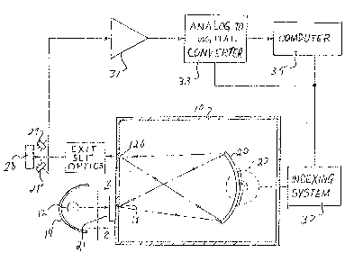
Figure 1 is a schematic drawing of a
spectrophotometer according to the present invention;
and
5Figure 2 is an enlarged fragmented view in
elevation showing the q~artz plate ln front of the
entrance slit of the spectrophotometer and taken along
line 2-2 of Fig. 1.
. .
:. .
' '
: ~ '

2031~87~ ~
DET~ILED D~SCRIPTION OF THE INVENTION
. = ~
As shown ln Figs. 1 and 2, the instrument of the
invention comprises a housing 10 containing a concave
holographic reflection diff~action grating 20,
positioned to be illuminated through an entrance slit
18 by a light source 12 in th~ form of a linear
filament infrared lamp. The lamp 12 geneLates light
with wavelengths distributed through the near infrared
spectrum. A reElector 14 in the shape of an
elliptical cylinder, partially encircles the light
source to reflect light radiated by the light source
12 toward the entrance slit 18. The elliptical
cylindrical shape of the reflector deEines a proximal
focal line along which the linear Eilament of the
light source 10 i5 positioned and a distal focal line
located approximately along the entrance slit 18 so
that an image of the filament is focused near the
entrance slit. Between the light source 12 and the
entrance slit 18 is an infrared light transmitting
plate 21 having a light diffusing interface. The
infrared light transmitting plate comprises a quartz
plate adjacent to the slit 18 with a ground surface
facing the slit~ The ground surface is the light
diffusing interface. Infrared light from the source
12 is transmitted through the plate to the ground
surface where the in~frared light is diffused ta
uniformly illuminate the entrance slit 18.
The slit 18 projècts the light with a uniform
angular~distribution~toward diffraction grating 20,
~hich is~oscilla5ed at high speed by means of a direct
drive motor 22. The details of the direct oscillating
motor drive are~disclosed in copending application
Serial No. ~9~,679,~f~iled January 9, 1989 invented by
Phillip A. McGee, and assigned to the assignee of this
,
;
,
,.
~. . : . .
.
: : ,
- , .
: ., :
~,
,: . :

7 -
application. The grating 20 dlsperses the inErared
light from the sllt la into a spectrum ~e~lected
toward an exit slit 26. A nar~ow wavelength band Erom
the spectrum passes through the exit slit 26 and
through exit slit optics before illumlnating sample
28. As the grating oscillates, the center wavelength
of the light passing through the exit slit is scanned
through the infrared spectrum. Photodetectors 29
detect the lntensity of the resulting radiation
reElected from the sample and generate an output
signal representing this in~ensity. The output signal
of the photodetectors 29 is amplified by an amplifier
31 and applied to an analog-to-digital converter 33.
As the grating oscillates and the center
wavelength of the narrow band passing through the exit
slit is scanned through the spectrum, the analog to
digital converter converts the output analog signal of
the amplifier to digital values at incremental index
points distributed through the spectrum so that a set
of digital values are obtained representing the
intensity of the reflected energy from the sample as
the wavelength irradiating the sample varies
throughout the spectrum~ These~ digital values are
received and processed by a computer 35.
2~ As shown ln Figure l, a shaft position indexing
system 37 coupled to the moto~ 22 transmits pulses to
the analog-to-digital;converter 33 and to the computer
35 as the motor 22 pivo~t~s the~grating 20 and scans the
wavèlength applied to the sample through the spectrum.
In response to each applied pulse, the analog-to-
digital-converter converts the analog signal received
from the amplifier 31 to a digital val~ue and in this
manner ~generates digital values representing the
intensit~ of the reflected r~adiation at increments
~, ~. : : :
,
-
,
:: :
'
.

2~3~687
dlstributed thruugh the spectrum. A computer 35counts the pulses received from the indexing system 37
and thereby monitors the angular position of the
grating 20 and the center wavelength of the band
currently being transmitted through the exit slit.
Thus, the computer 35 monitors the wavelength of
the band which caused the reflected intensity
represented by the digital signal currently applied to
the computer by the analog to digital converter.
Because the entrance slit is uniformly illuminated as
a result of the ground quartz plate, the shaft
position on ~hich the grating is mounted can be
accurately calibrated in terms oi the wavelength being
transmitted through the exit slit. Without the ground
l'; quartz plate to ensure uniform illumination of the
exit slit, variations in the illumination of the
entrance slit caused by hot spots in the light source
would cause an apparent shift in the entrance slit and
cause a corresponding shift in the spectrum reflected
by the grating, so that for a given shaft position of
the grating the wavelength transmitted through the
exit slit might vary by as much as 2 nanometers when
the lamp is replaced. With the ground quartz plate
distributing the light from the light source uniformly
over the entrance slit in accordance with the present
invention, the shift ~ in wavelength caused by
variations in the light source is reduced to 2/100 of
a nanometer. Thusj with the system of the present
~; ~ invention, the system does not need to be recalibrated
when the lamp of the light source is replaced.
The above description is of preferred embodiment
o~ the invention and modification may be made thereto
without departing from the spirit and scope of the
invention, which is defined in the appended claims.
, ~ .
:; :
.. ' ~ '
.
' ' '' ~ '
- . :
` ~ '
- ` '
: ' . . ~ .
. .
' ~ '
~ , ,

Representative Drawing
A single figure which represents the drawing illustrating the invention.
Administrative Status

2024-08-01:As part of the Next Generation Patents (NGP) transition, the Canadian Patents Database (CPD) now contains a more detailed Event History, which replicates the Event Log of our new back-office solution.

Please note that "Inactive:" events refers to events no longer in use in our new back-office solution.

For a clearer understanding of the status of the application/patent presented on this page, the site Disclaimer , as well as the definitions for Patent , Event History , Maintenance Fee  and Payment History  should be consulted.

Event History

Description Date
Inactive: IPC from MCD 2006-03-11
Application Not Reinstated by Deadline 2000-12-06
Time Limit for Reversal Expired 2000-12-06
Deemed Abandoned - Failure to Respond to Maintenance Fee Notice 1999-12-06
Amendment Received - Voluntary Amendment 1997-12-17
Letter Sent 1997-10-24
Inactive: Status info is complete as of Log entry date 1997-10-20
Inactive: Application prosecuted on TS as of Log entry date 1997-10-20
Request for Examination Requirements Determined Compliant 1997-09-24
All Requirements for Examination Determined Compliant 1997-09-24
Application Published (Open to Public Inspection) 1991-06-07

Abandonment History

Abandonment Date Reason Reinstatement Date
1999-12-06

Maintenance Fee

The last payment was received on 1998-10-06

Note : If the full payment has not been received on or before the date indicated, a further fee may be required which may be one of the following

  • the reinstatement fee;
  • the late payment fee; or
  • additional fee to reverse deemed expiry.

Patent fees are adjusted on the 1st of January every year. The amounts above are the current amounts if received by December 31 of the current year.
Please refer to the CIPO Patent Fees web page to see all current fee amounts.

Fee History

Fee Type Anniversary Year Due Date Paid Date
Request for examination - standard 1997-09-24
MF (application, 7th anniv.) - standard 07 1997-12-08 1997-12-03
MF (application, 8th anniv.) - standard 08 1998-12-07 1998-10-06
Owners on Record

Note: Records showing the ownership history in alphabetical order.

Current Owners on Record
NIRSYSTEMS INCORPORATED
Past Owners on Record
DAVID E. HONIGS
Past Owners that do not appear in the "Owners on Record" listing will appear in other documentation within the application.
Documents

To view selected files, please enter reCAPTCHA code :


To view images, click a link in the Document Description column. To download the documents, select one or more checkboxes in the first column and then click the "Download Selected in PDF format (Zip Archive)" or the "Download Selected as Single PDF" button.

List of published and non-published patent-specific documents on the CPD .

If you have any difficulty accessing content, you can call the Client Service Centre at 1-866-997-1936 or send them an e-mail at CIPO Client Service Centre.


Document
Description 
Date
(yyyy-mm-dd) 
Number of pages   Size of Image (KB) 
Abstract 1994-03-31 1 22
Claims 1994-03-31 3 127
Drawings 1994-03-31 1 50
Description 1994-03-31 7 264
Representative drawing 1999-07-18 1 15
Reminder - Request for Examination 1997-08-05 1 117
Acknowledgement of Request for Examination 1997-10-23 1 178
Courtesy - Abandonment Letter (Maintenance Fee) 2000-01-03 1 185
Fees 1996-09-19 1 52
Fees 1994-10-24 1 45