Language selection

Search

Patent 2031820 Summary

Third-party information liability

Some of the information on this Web page has been provided by external sources. The Government of Canada is not responsible for the accuracy, reliability or currency of the information supplied by external sources. Users wishing to rely upon this information should consult directly with the source of the information. Content provided by external sources is not subject to official languages, privacy and accessibility requirements.

Claims and Abstract availability

Any discrepancies in the text and image of the Claims and Abstract are due to differing posting times. Text of the Claims and Abstract are posted:

  • At the time the application is open to public inspection;
  • At the time of issue of the patent (grant).
(12) Patent Application: (11) CA 2031820
(54) English Title: DEVICE FOR PREPARING BULK MATERIAL WITH A DUST REMOVAL ARRANGEMENT
(54) French Title: DISPOSITIF DE PREPARATION DE MATERIAUX EN VRAC AVEC ELIMINATION DES POUSSIERES
Status: Deemed Abandoned and Beyond the Period of Reinstatement - Pending Response to Notice of Disregarded Communication
Bibliographic Data
(51) International Patent Classification (IPC):
  • B22C 5/10 (2006.01)
  • B22C 5/04 (2006.01)
(72) Inventors :
  • SATMER, FRANZ (Switzerland)
  • TRONDLE, ERNST (Germany)
(73) Owners :
  • GEORG FISCHER AG
(71) Applicants :
  • GEORG FISCHER AG (Switzerland)
(74) Agent: ROBIC AGENCE PI S.E.C./ROBIC IP AGENCY LP
(74) Associate agent:
(45) Issued:
(22) Filed Date: 1991-02-01
(41) Open to Public Inspection: 1991-06-16
Examination requested: 1994-02-01
Availability of licence: N/A
Dedicated to the Public: N/A
(25) Language of filing: English

Patent Cooperation Treaty (PCT): No

(30) Application Priority Data:
Application No. Country/Territory Date
04 527/89-7 (Switzerland) 1989-12-15

Abstracts

English Abstract


-7-
Abstract
Arranged in the upper region of a drum (1) which
rotates about an axis (2) there is a dust box (40) of
the dust removal device, which box is connected
with a line, which leads outwards, by way of a
laterally arranged discharge channel (48). Arranged
between the dust box (40) and a baffle rotor (3) which
rotates about the axis (2) there are baffle areas (51)
which form labyrinth-like passages for the dust to the
dust suction openings (42) in the dust box (40).
(Fig. 1)


Claims

Note: Claims are shown in the official language in which they were submitted.

-1-
Claims
1. Device for preparing bulk material, in batch
quantities, having a drum which can be rotated about a
horizontal axis, having a baffle rotor and having a
dust removal arrangement which has a suction box
arranged within the drum with a suction pipe which
leads outwards, characterised in that the suction box
(40) is formed in a curved manner, with the dust
suction openings (42) being arranged on the wall (41)
facing the drum centre and in that baffle areas (51)
are arranged between the suction box (40) and the
baffle rotor (3) such that labyrinth-like passages (57)
to the suction openings are formed for the dust.
2. Device according to claim 1, characterised in
that the suction box (40) is divided by means of an
intermediate wall (43), provided with through openings
(44), into an inner and an outer chamber (45, 46).
3. Device according to claim 2, characterised in
that the outer chamber (46) is connected, by means of a
lateral opening (47), with a discharge channel (48)
which is secured to a lateral end of the suction box
(40).
4. Device according to claim 3, characterised in
that the openings (42, 44) in the walls (41, 43) are
formed such that, starting from the lateral discharge
opening (48) as far as the opposing end of the chambers
(45, 46), they become continuously larger in cross
section in order to achieve uniform dust discharge over
the whole discharge width in the drum (1).
5. Device according to one of the claims 2 to 4,
characterised in that the wall (41) with the suction
openings (42) and the intermediate wall (43) are formed
as perforated metal sheet.
6. Device according to one of the claims 1 to 5,
characterised in that the baffle areas (51) are formed
by the legs (53) of angle sections (52).

-2-
7. Device according to claim 6, characterised in
that the angle sections (52) are arranged in at least
two rows, in each case offset in relation to each
other, with legs (53) open to the interior space of the
drum.
8. Device according to claim 6 or 7,
characterised in that additional baffle areas (51) are
formed by, in each case, metal sheets (54) which are
arranged between two angle sections (52).
9. Device according to one of the claims 1 to 8,
characterised in that at least one portion of the
baffle areas (51) is coated with rubber or plastics
material.

Description

Note: Descriptions are shown in the official language in which they were submitted.


20318~Q
--3--
Device for preparing bulk material with a dust removal
arranqement
The invention relates to a device for preparing
bulk material, in batch quantities, as described in the
preamble of claim 1.
Such a device has become known through DE-C2-29-09
408, which device has a suction box in the drum
interior for the removal of dust.
- The openings in the suction box for the suction
current lie directly behind a down-draught which is
generated by a stripper and meets with the baffle
rotor. As a result of this arrangement, a
comparatively large amount of bulk material or sand, as
the case may be, is also removed by suction in addition
to the dust, this bulk material or sand being lost with
regard to future use.
The object of the present invention is the
provision of a device of the kind mentioned by way of
introduction which renders possible optimum removal of
dust from the interior space of the drum with least
possible sand loss and suction power.
According to the invention this object is achieved
by means of the characterising features of claim 1.
Particularly advantageous developments of the
invention are characterised in the dependent claims.
As a result of the curved construction of the
suction box and the dust suction openings which are
directed to the centre of the drum, a suction current
develops outside the down-draught generated by the
stripper, while on account of the large suction
area only a comparatively low suction current speed is
required.
The result of the labyrinth-like arrangement of
the baffle areas between the suction box and the rotor
is that as few sand particles as possible, which have
been centrifuged away by the baffle rotor, reach the

2031820
--4--
suction box and are sucked in there as well.
The invention is represented by way of example in
the enclosed drawings and described in the following.
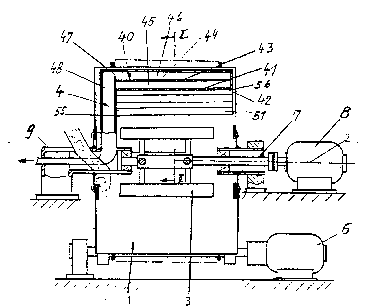
Figure 1 shows a longitudinal section of the
device along the drum axis in a simplified
representation.
Figure 2 shows a section along the line II - II in
an enlarged representation.
The represented device which operates with batch
quantities for the purpose of handling bulk material,
more particularly foundry sands, essentially consists t
of a drum 1, which rotates about a horizontal axis 2, a
baffle rotor 3, a dust removal arrangement 4 and a
stripper 5 which is shown in Figure 2. The drum is
driven by a motor 6.
There is mounted coaxially to the drum axis 2 a
shaft 7 which is driven by a motor 8 at a comparatively
high speed and supports the baffle rotor 3 in the
interior of the drum 1.
The dust removal arrangement 4 has a suction box
40 which is formed in a curved manner. The suction box
40 is arranged at a short distance from the inner
peripheral area of the drum 1 and is formed in cross
section as a partial circular ring. The inner wall 41
of the suction box 40 directed to the centre of the
drum has dust suction openings 42. An intermediate
wall 43 which runs parallel to the latter with through-
openings 44 divides the suction box 40 into an inner
chamber 45 and an outer chamber 46.
The two walls 41, 43 are preferably formed as
perforated metal sheets. The outer chamber 46 is
connected, by means of a lateral opening 47, with a
discharge channel 48 which is arranged at one lateral
end of the suction box 40. The discharge channel 48 is
formed, according to ~igure 2, substantially as a
segment or a circle in cross section and is secured by

203~820
--5--
means of a flanged connection 49 to a tubular holding
portion 9. In the interior of the holding portion 9
the discharge channel 48 is connected with a fan, by
means of a line, via a filter unit~
The holes 50 of the perforated metal sheets
forming the openings 42 and 44 are formed with
differing diameter in the direction along the drum
axis. Starting from the lateral discharge channel 48
as far as the opposing end of the chambers 45, 46, the
holes 50 are formed so as to become continuously larger
in diameter, whereby uniform dust discharge is achieved
over the whole discharge width of the drum, despite the
fact that the discharge channel 48 is arranged on one
side of the s~ction box 40~
There are arranged between the suction box 40 and
the rotor 3 baffle areas 51 between which labyrinth-
like passages 57 to the suction openings 42 are
arranged for the dust. The baffle areas 51 are formed
by the legs 53 of angle sections 52 which are arranged
in several rows with legs 53 open to the interior space
of the drum.
In the case of the exemplary embodiment
represented, four rows of angle sections 52 are
arranged so as to be offset in relation to each other,
the angle sec-tions 52 of the first and third row and
also the second and fourth row respectively being
connected with vertically arranged metal sheets 54
which form additional baffle areas 51. The angle
sections 52 are secured between one side wall 55 of the
discharge channel 48 and an opposite metal sheet 56
which is arranged at the end of the suction box 40.
The baffle areas 51 of the two lower rows of angle
sections 52, upon which the bulk material acts most
vigorously,are coated with rubber for the purpose of
reducing wear.
In addi-tion to the use of fixedly arranged angle

2~31820
--6--
sections as baffle areas, differently arranged
metal sheets can be used. These can also be formed so
as to be swingable about a point of rotation in order
to achieve, through adjustability, good dust removal
with small proportions of sand.

Representative Drawing
A single figure which represents the drawing illustrating the invention.
Administrative Status

2024-08-01:As part of the Next Generation Patents (NGP) transition, the Canadian Patents Database (CPD) now contains a more detailed Event History, which replicates the Event Log of our new back-office solution.

Please note that "Inactive:" events refers to events no longer in use in our new back-office solution.

For a clearer understanding of the status of the application/patent presented on this page, the site Disclaimer , as well as the definitions for Patent , Event History , Maintenance Fee  and Payment History  should be consulted.

Event History

Description Date
Application Not Reinstated by Deadline 1998-02-02
Time Limit for Reversal Expired 1998-02-02
Inactive: Application prosecuted on TS as of Log entry date 1997-10-17
Inactive: Status info is complete as of Log entry date 1997-10-17
Inactive: Abandoned - No reply to s.30(2) Rules requisition 1997-08-11
Inactive: S.30(2) Rules - Examiner requisition 1997-02-11
Deemed Abandoned - Failure to Respond to Maintenance Fee Notice 1997-02-03
Request for Examination Requirements Determined Compliant 1994-02-01
All Requirements for Examination Determined Compliant 1994-02-01
Application Published (Open to Public Inspection) 1991-06-16

Abandonment History

Abandonment Date Reason Reinstatement Date
1997-02-03
Owners on Record

Note: Records showing the ownership history in alphabetical order.

Current Owners on Record
GEORG FISCHER AG
Past Owners on Record
ERNST TRONDLE
FRANZ SATMER
Past Owners that do not appear in the "Owners on Record" listing will appear in other documentation within the application.
Documents

To view selected files, please enter reCAPTCHA code :


To view images, click a link in the Document Description column. To download the documents, select one or more checkboxes in the first column and then click the "Download Selected in PDF format (Zip Archive)" or the "Download Selected as Single PDF" button.

List of published and non-published patent-specific documents on the CPD .

If you have any difficulty accessing content, you can call the Client Service Centre at 1-866-997-1936 or send them an e-mail at CIPO Client Service Centre.


Document
Description 
Date
(yyyy-mm-dd) 
Number of pages   Size of Image (KB) 
Cover Page 1991-06-16 1 14
Drawings 1991-06-16 2 67
Abstract 1991-06-16 1 12
Claims 1991-06-16 2 52
Descriptions 1991-06-16 4 121
Representative drawing 1998-07-07 1 16
Courtesy - Abandonment Letter (R30(2)) 1997-10-20 1 172
Fees 1995-11-20 1 56
Fees 1993-11-18 1 42
Fees 1994-11-18 1 48
Fees 1992-11-19 1 35