Language selection

Search

Patent 2031907 Summary

Third-party information liability

Some of the information on this Web page has been provided by external sources. The Government of Canada is not responsible for the accuracy, reliability or currency of the information supplied by external sources. Users wishing to rely upon this information should consult directly with the source of the information. Content provided by external sources is not subject to official languages, privacy and accessibility requirements.

Claims and Abstract availability

Any discrepancies in the text and image of the Claims and Abstract are due to differing posting times. Text of the Claims and Abstract are posted:

  • At the time the application is open to public inspection;
  • At the time of issue of the patent (grant).
(12) Patent: (11) CA 2031907
(54) English Title: DISPENSING APPARATUS
(54) French Title: APPAREIL DISTRIBUTEUR
Status: Term Expired - Post Grant Beyond Limit
Bibliographic Data
(51) International Patent Classification (IPC):
  • A61M 11/00 (2006.01)
  • A61M 15/00 (2006.01)
  • B05B 17/06 (2006.01)
(72) Inventors :
  • ROSS, CALVIN JOHN (United Kingdom)
  • HUMBERSTONE, VICTOR CAREY (United Kingdom)
(73) Owners :
  • BESPAK PLC
(71) Applicants :
  • BESPAK PLC (United Kingdom)
(74) Agent: SMART & BIGGAR LP
(74) Associate agent:
(45) Issued: 1997-06-24
(22) Filed Date: 1990-12-10
(41) Open to Public Inspection: 1991-06-13
Examination requested: 1994-12-23
Availability of licence: N/A
Dedicated to the Public: N/A
(25) Language of filing: English

Patent Cooperation Treaty (PCT): No

(30) Application Priority Data:
Application No. Country/Territory Date
8928086 (United Kingdom) 1989-12-12
9017563 (United Kingdom) 1990-08-10

Abstracts

English Abstract


Dispensing apparatus (1) comprises a housing
(2) defining a chamber (3) receiving liquid (4) to be
dispensed and comprising a perforate membrane which
defines a front wall of the chamber. A vibrating
means (8) is connected to the housing and is operable
to vibrate the perforate membrane to dispense
droplets of liquid through holes (25) in the
perforate membrane. The housing comprises an
annular member (11) having a relatively thin inner
annular portion (68) connected to the perforate
membrane and a relatively thick outer annular portion
(66) connected to the vibrating means.
The apparatus is suitable for dispensing
pharmaceutical products as an atomised mist and
provides a hand-held inhaler for oral inhalation.


Claims

Note: Claims are shown in the official language in which they were submitted.

- 15 -
THE EMBODIMENTS OF THE INVENTION IN WHICH AN EXCLUSIVE PROPERTY
OR PRIVILEGE IS CLAIMED ARE DEFINED AS FOLLOWS:
1. Dispensing apparatus comprising a housing defining a chamber
receiving in use a quantity of liquid to be dispensed, the
housing comprising a perforate membrane which defines a front
wall of the chamber, the membrane having a rear face contacted by
the liquid in use, the apparatus further comprising vibrating
means connected to the housing and operable to vibrate the
perforate membrane by means of vibrations conducted through the
housing to dispense droplets of the liquid through the perforate
membrane, wherein the housing comprises an annular member having
a relatively thin inner annular portion connected to the
perforate membrane and a relatively thick outer annular portion
connected to the vibrating means, the annular member comprising a
disc defining a central aperture bounded by the inner annular
portion and traversed by the perforate membrane and wherein the
thickness of the disc tapers in a radially inward direction.
2. Dispensing apparatus as claimed in claim 1 wherein the disc
has front and rear faces which converge at an angle of taper
which varies with radius such that the inner annular portion has
a smaller angle of taper than that of the outer annular portion.
3. Dispensing apparatus as claimed in claim 1 wherein the
perforate membrane comprises a sheet defining an array of holes
through which liquid is dispensed in use and support means
supporting the sheet comprising a grid of support elements.
4. Dispensing apparatus as claimed in claim 3 wherein the
support elements are formed integrally with the sheet and
comprise thickened portions thereof.

- 16 -
5. Dispensing apparatus as claimed in claim 3 wherein the grid
of support elements comprises a plurality of circumferentially
spaced radially extending elements connected to an annular
support element defining a central portion of the sheet.
6. Dispensing apparatus as claimed in claim 1 wherein at least
a front face of the perforate membrane comprises a liquid
repellant surface.
7. Dispensing apparatus as claimed in claim 1 wherein the
vibrating means comprises a transducer removably connected to the
housing and whereby in use the housing from which liquid has been
dispensed can be replaced by a further housing charged with
liquid.
8. Dispensing apparatus as claimed in claim 1 wherein the
perforate membrane defines an array of holes each provided with a
flared mouth formed in the rear face of the membrane whereby the
hole tapers in cross-section in a direction towards a front face
of the membrane.
9. Dispensing apparatus as claimed in claim 1 wherein the
perforate membrane comprises an electroformed metal sheet.
10. Dispensing apparatus comprising a housing defining a chamber
receiving in use a quantity of liquid to be dispensed, the
housing comprising a perforate membrane which defines a front
wall of the chamber and which has a rear face contacted by liquid
in use, the apparatus further comprising vibrating means
connected to the housing and operable to vibrate the perforate
membrane to dispense droplets of liquid through the perforate
membrane, wherein the perforate membrane comprises a sheet
defining an array of holes through which liquid is dispensed in
use and support means supporting the sheet comprising a grid of
support elements.

- 17 -
11. Dispensing apparatus as claimed in claim 10 wherein the
support elements are formed integrally with the sheet and
comprise thickened portions thereof.
12. Dispensing apparatus as claimed in claim 10 wherein the
support means comprises a plurality of circumferentially spaced
radially extending elements connected to an annular support
element defining a central portion of the sheet.
13. Dispensing apparatus comprising a housing defining a chamber
receiving in use a quantity of liquid to be dispensed, the
housing comprising a perforate membrane which defines a front
wall of the chamber and which has a rear face contacted by liquid
in use, the apparatus further comprising vibrating means
connected to the housing and operable to vibrate the perforate
membrane to dispense droplets of liquid through the perforate
membrane, the housing comprising an annular member having a
relatively thin inner annular portion connected to the perforate
membrane and a relatively thick outer annular portion connected
to the vibrating means, wherein the perforate membrane comprises
a sheet defining an array of holes through which liquid is
dispensed in use and support means supporting the sheet
comprising a grid of support elements.
14. Dispensing apparatus as claimed in claim 13, wherein the
support elements are formed integrally with the sheet and
comprise thickened portions thereof.
15. Dispensing apparatus as claimed in claim 13, wherein the
grid of support elements comprises a plurality of
circumferentially spaced radially extending elements connected
to an annular support element defining a central portion of the
sheet.
16. Dispensing apparatus comprising a housing defining a chamber

- 18 -
receiving in use a quantity of liquid to be dispensed, the
housing comprising a perforate membrane which defines a front
wall of the chamber and which has a rear face contacted by liquid
in use, the apparatus further comprising vibrating means
connected to the housing and operable to vibrate the perforate
membrane to dispense droplets of liquid through the perforate
membrane, the housing comprising an annular member having a
relatively thin inner annular portion connected to the perforate
membrane and a relatively thick outer annular portion connected
to the vibrating means, wherein the perforate membrane defines an
array of holes each provided with a flared mouth formed in the
rear face of the membrane whereby the hole tapers in
cross-section in a direction towards a front face of the membrane.
17. A method of dispensing liquid as an atomised spray
comprising the steps of containing a quantity of liquid in a
chamber defined by a housing, said housing comprising a perforate
membrane defining a front wall of the chamber whereby the
membrane has a rear face contacted by the liquid, and operating a
vibrating means connected to the housing to produce vibrations
conducted through the housing to the perforate membrane whereby
droplets of the liquid are dispensed through the perforate
membrane, the method including the step of amplifying the
amplitude of vibrations conducted to the perforate membrane by
means of the housing comprising a disc defining a central
aperture bounded by an inner annular portion connected to the
perforate membrane, said disc tapering in thickness in a radially
inward direction such that vibrations conducted in said radially
inward direction from the vibrating means to the perforate
membrane are amplified.

Description

Note: Descriptions are shown in the official language in which they were submitted.


2031~07
"DISPENSING APPARATUS"
This invention relates to dispensing apparatus
for use in dispensing liquid as an atomised spray and
in particular but not exclusively to medical
atomisers.
It is known to produce a stream of liquid
droplets by vibrating a perforate membrane having a
rear face contacted by liquid such that droplets are
expelled from holes in the membrane at each cycle of
vibration. The size of droplet produced will depend
upon the hole size and for practical purposes the
thickness of the membrane will tend to be of the same
order of magnitude as the hole size. Consequently
it has hitherto not been practicable to use such
apparatus for the production of an atomised spray for
use in applications such as medical inhalers where
for example droplet size of less than 10 microns may
be required.
It is known from US-4533082 to provide
dispensing apparatus comprising a housing defining a
chamber receiving in use a quantity of liquid to be
dispensed, the housing comprising a perforate member
which defines a front wall of the chamber and which
has a rear face contacted by liquid in use, the
apparatus further comprising vibrating means
connected to the housing and operable to vibrate the
perforate membrane to dispense droplets of liquid
through the perforate membrane.
The present invention is characterised in that
the housing comprises an annular member having a
relatively thin inner annular portion connected to
the perforate membrane and a relatively thick outer
annular portion connected to the vibrating means.
An advantage of this arrangement is that the
vibrating means is presented with a relatively high

2031907
-- 2
acoustic impedance compared with a relatively low
impedance found in the inner annular portion so that
the amplitude of vibration transmitted to the
perforate member is amplified during transmission of
transverse acoustic waves through the annular member.
An efficient arrangement is thereby attainable
when vibrating the perforate membrane at the higher
frequencies favoured for the production of smaller
droplets.
Preferably the annular member comprises a disc
defining a central aperture bounded by the inner
annular portion and traversed by the perforate
membrane and wherein the thickness of the disc tapers
in a radially inward direction.
Such a disc may be regarded as an impedance
transformer in which the outer annular portion is
matched in impedance to a vibrating means such as a
piezoelectric transducer and the inner annular
portion is matched in impedance to the perforate
membrane.
Advantageously the disc has front and rear
faces which converge at an angle of taper which
varies with radius such that the inner annular
portion has a smaller angle of taper than that of the
outer annular portion.
The perforate membrane may comprise a sheet
defining an array of holes through which liquid is
dispensed in use and may include support means
supporting the sheet comprising a grid of support
elements.
Such support means has the advantage of
providing stiffness to sheets which may be formed of
very thin material in order to facilitate the
provision of correspondingly small hole diameters.
A further surprising advantage is that the proportion
of holes which dispense droplets is enhanced by the

2031907
-- 3
presence of support elements and those holes in close
proximity with a support element are found to be more
likely to dispense droplets than would otherwise be
the case.
Conveniently the support elements are formed
integrally with the sheet and comprise thickened
portions thereof.
Preferably the support means comprises a
plurality of circumferentially spaced radially
extending elements connected to an annular support
element defining a central portion of the sheet.
Such an arrangement is believed to operate more
effectively than support means in which the radially
extending elements meet at a central location of the
sheet. The central portion of the sheet defined by
the annular support element is found to operate
efficiently in the production of droplets.
Preferably at least a front face of the
perforate membrane comprises a liquid repellant
surface. A suitable surface coating may
conveniently be applied to the membrane to render the
surface liquid repellant.
Efficient dispensing operation requires that
the front face of the membrane should not be wetted
by the liquid. The use of a liquid repellant
surface coating inhibits such wetting and thereby
improves efficiency.
Conveniently the vibrating means comprises a
transducer removably connected to the housing whereby
in use a housing from which liquid has been dispensed
can be replaced by a further housing charged with
liquid.
Advantageously the perforate membrane defines
an array of holes each provided with a flared mouth
formed in the rear face of the membrane whereby the
hole tapers in cross-section in a direction towards a

_ 4 _ 20 3 19 0 7
front face of the membrane.
The presence of the taper facilitates the flow
of liquid particularly where the liquid to be
dispensed contains a particulate substance in
suspension. The presence of the taper is believed
to prevent clogging of the holes by accummulation of
particulate material.
Preferably the perforate membrane comprises an
electroformed metal sheet. Such sheets may be
manufactured to any desired thickness and the size
and shape of holes can be controlled using a
photographic process. A result of such a process is
the formation of tapered holes on one side of the
sheet which has the particular advantage referred to
above.
Preferred embodiments of the present invention
will now be described by way of example only and with
reference to the accompanying drawings of which:-
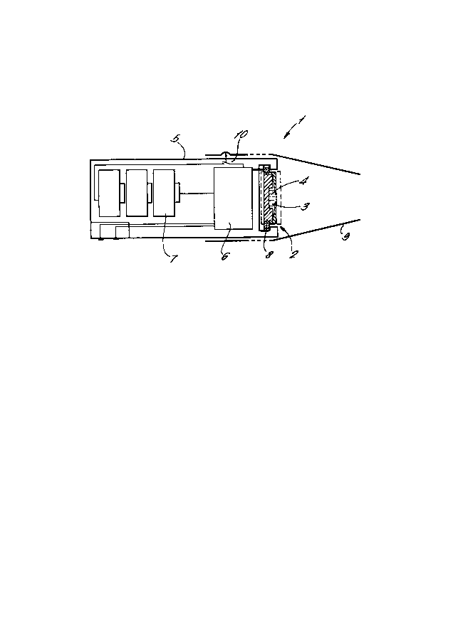
Figure 1 is a schematic section of a hand held
dispensing apparatus;
Figure 2 is a schematic section of theapparatus of Figure 1 connected to an electronic
control unit;
Figure 3 is a sectional elevation of the spray
head of the apparatus of Figures 1 and 2;
Figures 4, 5, 6 and 7 are sectional elevations
of further alternative spray heads;
Figure 8 is a view of the rear face of a
perforate membrane for use in a spray head of any of
the preceding figures;
Figure 9 is a sectioned elevation of a
perforate sheet portion of the perforate membrane of
Figure 8; and
Figure 10 is a plan view of a perforate sheet
portion of the perforate membrane of Figure 8.
Figure 1 shows dispensing apparatus 1 which is

2031907
-- 5 --
a hand held inhaler for medical use. Apparatus 1
comprises a housing 2 defining a chamber 3 containing
liquid 4 to be dispensed.
The housing 2 is mounted on a hand held casing
5 within which is located an electronic control
circuit 6 and batteries 7. An electro acoustic
transducer 8 of the piezoelectric type is mounted on
the housing 2 and is powered and controlled by the
control circuit 6. A mouthpiece 9 fits slidably on
the casing 5 and movement of the mouthpiece 9
relative to the casing actuates an on-off switch 10.
The detailed construction of the housing 2 and
transducer 8 can be seen from Figure 3. The housing
comprises a disc ll having a central aperture 12 with
a thin perforate membrane 13 bonded to the disc so as
to overlay the aperture. The construction of a
suitable membrane 13 is described below with
reference to Figures 8 and 9. The membrane 13 is
perforated by a large number of holes 25 of which
only a few are included in Figure 3 by way of
schematic representation. The disc 11 has a flat
front face 14 and a frusto-conical rear face 15 so
that the disc tapers linearly in thickness in the
radially inward direction towards the perforate
membrane 13.
The disc 11 has a periphery 16 from which
projects rearwardly a tubular portion 17.
The housing 2 also includes a circular base 18
which fits within the tubular portion 17 so that a
chamber 3 is defined between the base and the disc
11. The base 18 has a front face 19 having a central
recess 20 such that the chamber 3 is deepest in the
region adjacent to the membrane 13.
An annular rib 21 is formed on the base 18
peripherally of the front face 19 and locates in an
annular groove 22 formed in the disc 11 thereby

20~907
-- 6 --
sealing the chamber 3. An annular space 29 is formed
between the tubular portion 17 and the base 18.
The transducer 8 is a circular ring
piezoelectric element and is bonded to a rearward end
23 of the tubular portion 17.
The transducer 8 is arranged such that when
energised with an alternating voltage the transducer
expands and contracts radially to impart an
ultrasonic vibration to the tubular portion 17. The
thickness of the rearward end 23 (measured in the
direction in which it is vibrated by the transducer)
is considerably thicker than the thickness of the
disc 11 at the point of contact with the membrane
13. The disc 11 flexes in response to radially
outward movement of the transducer by pivotal action
about the annular rib 21 so as to move the membrane
13 axially towards the base 18. On radial
contraction of the transducer 8 pivotal action about
the rib 21 causes flexure of the disc so as to move
the membrane 13 away from the base 18. At ultrasonic
frequencies however the movement of the disc 11 can
be characterised more in terms of transmission of
transverse acoustic wave motion in a direction
radially inward through the disc 11. The effect of
the taper present in the shape of the disc 11 results
in the amplitude of such transverse vibrations
increasing progressively in the radially inward
direction to thereby maximise the axial displacement
of the membrane 13. The increase in amplitude is
associated with the decreasing impedance of the disc
11 in the radially inward direction.
In use to dispense liquid, the apparatus 1 is
held in an orientation in which liquid 4 is in
contact with the rear surface 24 of the perforate
membrane 13. Prior to actuation of the transducer 8
there will generally be no loss of liquid through the

7 2031907
holes 25 in the membrane 13 since a liquid surface
formed in the holes will generally have sufficient
surface tension to resist the outflow of liquid.
Dispensing operation is commenced by the user
actuating the switch 10 so that the transducer 8 is
energised to vibrate at ultrasonic frequency. This
vibration is conducted by the disc 11 to the
perforate membrane 13. During rearward motion of the
vibrating membrane 13 an instantaneous pressure rise
in the liquid adjacent to the membrane will result in
the surface tension being overcome and droplets of
liquid being ejected through the holes 25.
A fine mist of atomised liquid is dispensed
through the membrane 13 into the mouthpiece 9 and is
inhaled by the user.
The apparatus 1 is shown in its normal
orientation for oral dispensing in which the membrane
13 is approximately vertical.
Continued operation will deplete the quantity
of liquid within the chamber 4 so that eventually
dispensing will no longer be possible once there is
no liquid in contact with the rear surface 24 of the
membrane 13. The recess 20 in the base 18 ensures
that the bulk of the liquid is stored adjacent to the
membrane 13 to thereby minimise the amount of liquid
wastage which occurs when there is insufficient
liquid remaining in the chamber 3 for dispensing
operation to continue.
The apparatus 1 may be programmed to deliver a
predetermined dose of atomised liquid by means of a
timer within the control circuit 6 which allows the
transducer 8 to be energised for a predetermined time
period. The control circuit 6 may be programmed by
means of an electronic control unit 26 as shown
schematically in Figure 2, the control unit having a
keyboard 27 for the input of data.

2031907
- 8 -
Once the supply of liquid 4 is exhausted or
depleted to the extent of being unusable a
replacement housing 2 can be fitted to the casing 5
and containing a new supply of liquid.
The housing 2 is arranged to be received as a
sliding fit within the transducer 8 for ease of
replacement.
The housing 2 and the transducer 8 together
comprise a spray head 28. An alternative spray head
30 as shown in Figure 4 will now be described.
Corresponding reference numerals to those of
preceding figures are used where appropriate for
corresponding elements.
The alternative spray head 30 has a base 18
including an annular flange 31 constituting a side
wall of the chamber 4. The flange 31 has a lip 32 to
which the disc 11 is bonded such that a peripheral
portion 33 of the disc projects radially outward from
the flange 31.
The base 18 of the alternative spray head 30
includes a radially projecting portion 34 and a
piezoelectric transducer 8 is located outboard of the
flange 31 in contact with the peripheral portion 33
of the disc 11 and the radially projecting portion 34
of the base 18. The transducer 8 is of a type
producing axial expansion and contraction when
energised such that when actuated by the control
circuit 6 it produces an ultrasonic vibration of the
peripheral portion 33.
This vibration is communicated by pivotal
action about the lip 32 to the perforate membrane
13. Ultrasonic transverse waves transmitted radially
inwardly through the disc 11 are amplified by virtue
of a linear taper of the disc 11.
Liquid 4 in contact with the rear surface of
the membrane 13 is dispensed through holes 25 as a

- 9 - 203 1 9 07
fine atomised mist.
A further alternative spray head 40 is shown in
Figure 5 and will be described using reference
numerals corresponding to those of previous figures
where appropriate for corresponding elements.
The spray head 40 includes a disc 11 having a
planar front face 14 and a dished rear face 41. The
rear face 41 is profiled such that the thickness of
the disc 11 tapers radially inwardly in an
approximately exponential manner. The disc 11
includes a rearwardly extending tubular portion 42
having an internal surface 43 which merges smoothly
with the rear surface 41. A plate 44 is located
within the tubular portion 42 so as to constitute a
rear wall of the chamber 4. A piezoelectric disc
transducer 45 is bonded centrally to the plate 44 and
is of a type which expands and contracts radially
when energised.
In use the transducer 45 is energised so as to
vibrate radially at ultrasonic frequencies and this
vibration is communicated through the plate 44 to the
tubular portion 42. Transverse wave motion is
propagated through the tubular portion in an axial
direction and is conducted along a curved path
following approximately the curvature of the rear
surface 41 to vibrate the perforate membrane 13. The
amplitude of this vibration is progressively
amplified by virtue of the tapered thickness of the
disc 11.
The plate 44 and transducer 45 are renewable
together with the disc 14 when a fresh housing 2 is
fitted into an apparatus 1 with a fresh supply of
liquid 4.
A further alternative spray head 50 is shown in
Figure 6 and is described with corresponding
reference numerals to those of Figure 5 for

2031~07
-- 10 --
corresponding elements where appropriate.
The spray head 50 includes a disc 11 having a
dished rear face 41 and a tubular portion 42. An
internal surface 43 of the tubular portion 42 is
stepped to provide a shoulder 51 against which a
plate 44 is located and bonded. The plate 44
supports a central disc transducer 45 arranged to
radially vibrate the membrane.
The spray head 50 differs from the spray head
40 of Figure 5 in that the tubular portion 42 is
thinner in radial width than the corresponding
tubular portion of Figure 5 and provides a shoulder
51 for positively locating the plate 44.
The thickness of the membrane 13 in the above
apparatus can be typically in the range 1 to 80
microns. The size of holes 25 can be typically of
the range 1 to 200 microns depending on the required
droplet size. The apparatus is however particularly
useful in applications where small droplets are
required such that the thickness of the membrane 13
and the size of the holes 25 are less than 20
microns. The membrane 13 may be provided with holes
25 of uniform or non-uniform hole size depending on
the required distribution of droplet size.
A further alternative spray head 60 is shown in
Figure 7 where corresponding reference numerals to
those of previous figures are used where appropriate
for corresponding elements.
The spray head 60 has a disc 11 formed of
aluminium alloy and having a circular planar front
face 14 of 22mm diameter. An annular piezoelectric
transducer 8 having an internal radius of lOmm is
bonded to a peripheral portion 61 of the front face
14 so as to be radially spaced from a circular
central aperture 12 of the disc 11 having a diameter
of 4mm.

- 11 - 2~1907
The disc 11 tapers in thickness in the radially
inward direction such that a rear face 15 of the disc
11 has an outer annular portion 62 which tapers at an
angle of 20 relative to the front face 14 when
viewed in radial section and an inner annular portion
63 which tapers at an angle of 10 relative to the
planar front face 14. The inner annular portion 63
joins the outer annular portion 62 at a circular
interface 64 which is adjacent the radially inner
edge 65 of the transducer 8. The transducer 8
thereby is bonded to a relatively thick outer portion
66. A relatively slender inner portion 67 of the
disc 11 defines the aperture 12.
A perforate membrane 13 overlays the aperture
12 and is bonded to an edge portion 68 of the inner
portion 67. The perforate membrane 13 as shown in
Figures 8 and 9 comprises a nickel sheet 69 having an
integrally formed support 70 in the shape of a grid
having circular symmetry as shown in Figure 8.
The support 70 comprises thickened elements 72,
73 and 74 of the membrane 13 defining a series of
apertures 71 which expose corresponding portions of
the sheet 69. The support 70 has an outer annular
element 72 which is connected to an inner annular
element 73 by radial elements 74 defining the
apertures 71 therebetween. A central aperture 75 is
defined within the inner annular element 73 thereby
exposing a central portion 76 of the sheet 69. The
membrane 13 is formed in an electroforming process in
which nickel is electro-deposited on selected areas
of a substrate masked using a photographic process
and the resulting sheet 69 is then detached from the
substrate. The outer annular element 72 of the
support 70 is bonded to the edge portion 68 so that
vibration of the disc is conducted through the
support to the sheet 69.

20~1907
- 12 -
The membrane 13 is coated in a liquid repellant
coating 80 using a commercially available surface
treatment process in which sub-micron particles of
polytetrafluroethylene are incorporated in a nickel
phosphorous matrix which is auto-catalytically
applied to the nickel material of the sheet 69 and
support 70. A small proportion of phosphorous
co-deposited with the nickel enhances the corrosion
resistance of the resulting finish.
As shown in Figures 9 and 10 the sheet 69
includes a regular array of circular holes 77 and has
a front face 78 to which the support 70 is bonded.
The sheet 69 has a rear face 79 which is normally
contacted by liquid 4 and the holes 77 are flared
such that the cross-section of each hole narrows in a
direction from the rear face 79 towards the front
face 78.
The resulting holes 77 in the sheet 6g are of 3
microns diameter and 25 microns spacing. The
resulting droplets are formed in the range 5 to 7
microns when dispensing a pharmaceutical product in
aqueous solution, this droplet size being suitable
for delivery of atomised products to the lungs of a
patient. A typical flow rate in the range 10 to 20
cubic millimetres per second is achieved, the flow
rate being dependent on the power and frequency with
which the transducer 8 is driven.
The sheet 69 includes approximately 1500 holes
77 of which only a proportion will emit droplets in
use. Those of the holes 77 which do emit droplets
tend to be concentrated in regions adjacent to the
thickened elements 72, 73 and 74 and also in the
central portion 76. The number of such holes 77
which do emit droplets will also depend on the
amplitude of vibration induced in the membrane 13 and
in a typical example the proportion of holes which

20~907
- 13 -
emit droplets is about 10%.
The size of the droplets produced is closely
dependent on the diameter of the holes 77 so that for
different applications it may be necessary to use a
sheet having different hole size.
Apparatus in accordance with the present
invention may be used to dispense products in
solution or suspension. Pharmaceutical products
will generally require the presence of a preservative
in aqueous solution such as benzalkonium chloride
which has a tendency to reduce the surface tension of
the resulting solution. When dispensing such
solutions it is particularly important for the sheet
69 to be treated with a liquid repellant coating and
for the external surface of the sheet to be as smooth
as possible in order to reduce the tendency of the
solution to wet the external surface of the sheet.
Alternative liquid repellant coatings may be used
such as silanes, fluorosilanes, micronised PTFE
(polytetrafluoroethylene) particles and PTFE applied
and heated in situ to form a conformal coating.
The control circuit 6 includes a simple
oscillator circuit arranged to drive the transducer 8
at a frequency typically in the range of 3KHz to lMHz
selected to be at resonant frequency of the
transducer in order to maximise efficiency. The
resonant frequency of the transducer 8 is matched to
that of the disc 11 so as to achieve maximum
amplitude of vibration at the membrane 13.
The chamber 3 containing liquid 4 is a closed
chamber which would not normally have any means of
inducing excess pressure within the chamber. The
emission of atomised spray droplets through the
membrane 13 is achieved in the above embodiments
solely by vibration of the membrane and not by
supplying excess pressure to the liquid by other

20319~7
- 14 -
means.
The vibration of the membrane 13 achieved by
the apparatus of the present invention does not rely
on the transmission through the liquid 4 of
ultrasonic waves so that problems associated with
cavitation in the liquid are avoided.
The apparatus will function in any orientation
provided the level of liquid 4 in the chamber 3 is
such that liquid is maintained in contact with the
rear surface 79 of the perforate membrane 13.
The apparatus may optionally be provided with a
sensor responsive to inhalation by the user through
the mouthpiece. The control circuit may then be
programmed to dispense only after commencement of
inhalation has been sensed.
Control circuitry for the apparatus may include
a memory and microprocessor to monitor the
accumulative dispensed volume and control the
duration of delivery and the time interval between
successive deliveries. The apparatus may also
optionally be provided with visual or audible
indicators to provide indication of for example
elapsed time since last use, warning that the
remaining liquid is nearly depleted and indication
that the next dispensing cycle is due.
The membrane may alternatively be provided with
holes which are other than circular. The membrane
may alternatively comprise a perforate sheet without
having a support. Where a membrane is provided with
a support, the support may be other than of circular
symmetry and may for example be in the form of a
rectangular grid.

Representative Drawing
A single figure which represents the drawing illustrating the invention.
Administrative Status

2024-08-01:As part of the Next Generation Patents (NGP) transition, the Canadian Patents Database (CPD) now contains a more detailed Event History, which replicates the Event Log of our new back-office solution.

Please note that "Inactive:" events refers to events no longer in use in our new back-office solution.

For a clearer understanding of the status of the application/patent presented on this page, the site Disclaimer , as well as the definitions for Patent , Event History , Maintenance Fee  and Payment History  should be consulted.

Event History

Description Date
Inactive: Expired (new Act pat) 2010-12-10
Inactive: IPC from MCD 2006-03-11
Grant by Issuance 1997-06-24
Notice of Allowance is Issued 1997-01-21
Request for Examination Requirements Determined Compliant 1994-12-23
All Requirements for Examination Determined Compliant 1994-12-23
Application Published (Open to Public Inspection) 1991-06-13

Abandonment History

There is no abandonment history.

Fee History

Fee Type Anniversary Year Due Date Paid Date
MF (patent, 7th anniv.) - standard 1997-12-10 1997-09-30
MF (patent, 8th anniv.) - standard 1998-12-10 1998-11-18
MF (patent, 9th anniv.) - standard 1999-12-10 1999-10-15
MF (patent, 10th anniv.) - standard 2000-12-11 2000-11-21
MF (patent, 11th anniv.) - standard 2001-12-10 2001-10-12
MF (patent, 12th anniv.) - standard 2002-12-10 2002-11-08
MF (patent, 13th anniv.) - standard 2003-12-10 2003-10-24
MF (patent, 14th anniv.) - standard 2004-12-10 2004-11-10
MF (patent, 15th anniv.) - standard 2005-12-12 2005-11-10
MF (patent, 16th anniv.) - standard 2006-12-11 2006-12-04
MF (patent, 17th anniv.) - standard 2007-12-10 2007-11-13
MF (patent, 18th anniv.) - standard 2008-12-10 2008-11-10
MF (patent, 19th anniv.) - standard 2009-12-10 2009-11-10
Owners on Record

Note: Records showing the ownership history in alphabetical order.

Current Owners on Record
BESPAK PLC
Past Owners on Record
CALVIN JOHN ROSS
VICTOR CAREY HUMBERSTONE
Past Owners that do not appear in the "Owners on Record" listing will appear in other documentation within the application.
Documents

To view selected files, please enter reCAPTCHA code :


To view images, click a link in the Document Description column. To download the documents, select one or more checkboxes in the first column and then click the "Download Selected in PDF format (Zip Archive)" or the "Download Selected as Single PDF" button.

List of published and non-published patent-specific documents on the CPD .

If you have any difficulty accessing content, you can call the Client Service Centre at 1-866-997-1936 or send them an e-mail at CIPO Client Service Centre.


Document
Description 
Date
(yyyy-mm-dd) 
Number of pages   Size of Image (KB) 
Abstract 1997-05-05 1 22
Description 1997-05-05 14 605
Claims 1997-05-05 4 181
Drawings 1997-05-05 4 74
Cover Page 1993-12-14 1 12
Abstract 1993-12-14 1 18
Description 1993-12-14 14 523
Claims 1993-12-14 2 68
Drawings 1993-12-14 4 66
Cover Page 1997-05-05 1 15
Representative drawing 1999-07-14 1 6
Fees 2001-10-12 1 29
Fees 2003-10-24 1 31
Fees 1998-11-18 1 32
Fees 2000-11-21 1 30
Fees 2002-11-08 1 31
Fees 1997-09-30 1 32
Fees 1999-10-15 1 26
Fees 2004-11-10 1 27
Fees 2005-11-10 1 25
Fees 2006-12-04 1 27
Fees 2007-11-13 1 28
Fees 2008-11-10 1 34
Fees 2009-11-10 1 34
Fees 1996-09-30 1 39
Fees 1994-10-07 1 40
Fees 1995-10-06 1 36
Fees 1992-10-21 1 29
Fees 1993-09-29 1 33
Prosecution correspondence 1995-04-13 2 44
Prosecution correspondence 1995-04-18 1 26
Prosecution correspondence 1994-12-23 2 49
PCT Correspondence 1997-03-20 1 31
Courtesy - Office Letter 1991-03-28 1 36