Language selection

Search

Patent 2032047 Summary

Third-party information liability

Some of the information on this Web page has been provided by external sources. The Government of Canada is not responsible for the accuracy, reliability or currency of the information supplied by external sources. Users wishing to rely upon this information should consult directly with the source of the information. Content provided by external sources is not subject to official languages, privacy and accessibility requirements.

Claims and Abstract availability

Any discrepancies in the text and image of the Claims and Abstract are due to differing posting times. Text of the Claims and Abstract are posted:

  • At the time the application is open to public inspection;
  • At the time of issue of the patent (grant).
(12) Patent Application: (11) CA 2032047
(54) English Title: MAT HOLDERS
(54) French Title: DISPOSITIFS DE RETENUE DE TAPIS
Status: Deemed Abandoned and Beyond the Period of Reinstatement - Pending Response to Notice of Disregarded Communication
Bibliographic Data
(51) International Patent Classification (IPC):
  • A47L 23/22 (2006.01)
  • A47G 27/02 (2006.01)
  • A47G 27/04 (2006.01)
  • A47L 23/26 (2006.01)
(72) Inventors :
  • MOGEL, PHILIP (United Kingdom)
  • CALVERT, JOHN (United Kingdom)
(73) Owners :
  • KIMBERLY-CLARK LIMITED
  • KIMBERLY-CLARK LIMITED
(71) Applicants :
  • KIMBERLY-CLARK LIMITED (United Kingdom)
  • KIMBERLY-CLARK LIMITED (United Kingdom)
(74) Agent: BORDEN LADNER GERVAIS LLP
(74) Associate agent:
(45) Issued:
(22) Filed Date: 1990-12-13
(41) Open to Public Inspection: 1991-06-16
Examination requested: 1997-11-13
Availability of licence: N/A
Dedicated to the Public: N/A
(25) Language of filing: English

Patent Cooperation Treaty (PCT): No

(30) Application Priority Data:
Application No. Country/Territory Date
8928367.5 (United Kingdom) 1989-12-15

Abstracts

English Abstract


ABSTRACT
IMPROVEMENTS IN AND RELATING TO MAT HOLDERS
A holder (6) for a floor mat comprises at least one
connecting means (14, 16) and at least one connecting
member (20, 26, 30) which has complementary connection
means (22, 28, 32), whereby the connecting member may be
connected in a releasable manner to at least two adjacent
mat holders so as to secure the mat holders together.
Preferably at least one of the holder or the connecting
member are made from flexible material or are designed to
be slightly flexible.


Claims

Note: Claims are shown in the official language in which they were submitted.

What we claim is :-
1. A holder for a flexible floor mat comprising at least
one connecting means and at least one connecting member
which has complementary connecting means, whereby the
connecting member may be connected in a releasable manner
to at least two adjacent mat holders, so as to secure the
holders together.
2. A holder as claimed in claim 1 wherein one of the base
of the holder or the connecting member is provided with
holes which are engageable with lugs provided on the other.
3. A holder as claimed in claim 2 wherein the holes
extend through the base of the holder.
4. A holder as claimed in any preceding claim wherein the
connecting member includes a tongue which extends through
a slot provided in the base of the holder, such that the
tongue lies against the top surface of the base.
5. A holder as claimed in any of the preceding claims,
wherein the holder and/or the connecting member is made
from a flexible material.
6. A holder as claimed in claim 5 wherein the flexible
material is rubber or a rubber substitute.
7. A holder as claimed in any preceding claim wherein the
connecting member is made of polypropylene.
8. A connecting member for use with a holder as claimed
in any preceding claim comprising an elongated body having
connecting means at or adjacent either end.
9. A connecting member as claimed in claim 8 wherein the
connecting member includes at least one aperture between
the connecting means of the member.
10. A connecting member as claimed in claim 9 wherein the
aperture comprises thin elongated slots which extend
between the connecting means.
11. A holder substantially as hereinbefore described with
reference to the accompanying drawings.

12. A connecting member substantially as hereinbefore
described with reference to the accompanying drawings.

Description

Note: Descriptions are shown in the official language in which they were submitted.


~7~
_PROVEMENTS IN AND REL~TING TO M~T ~IOLDERS
This invention relates to mat holders generally and
more particularly to holders ~or disposable floor mats.
Floor mats which are intended to be disposable may be
made of paper or synthetic fabrics and rest directly on the
floor. ~owever, in this case, the mats tend to become
displaced and/or torn and so do not adequately carry out
the function for which they are designed. Holders have
therefore been developed to hold the mats in position on
the floor and to protect the edges of the mat. This
greatly prolongs the life of each disposable mat.
One such mat holder is described in our European
Patent Publication No 260864. The holder has a base on
which the mat rests and side flaps which clamp the mat in
place. The holder is then placed in the desired location.
Another such holder is described in the Applicant's British
Patent Application No. 8920349.
These mat holders are suitably manufactured in one
piece and are usually made in a limited number of standard
sizes. When a mat is required to cover an area greater
than the maximum available size of a holder, more than one
holder will therefore be required. With this arrangement,
the holders tend to become separated when walked over, and
so undesirably expose areas of the floor and also edges of
the holder over which people may trip.
In accordance with the invention a holder for a floor
mat comprises at least one connecting means and at least
one connectiny member, which has complementary connection
means whereby the connecting member may be connected in a
releasable manner to at leask two adjacent mat holders, so
as to secure the holders together.
This allows two adjacent holders to be connected
together in such a wa~ that the holders are generally
unable to be separated when a lateral force is exerted on

~$32~
the holder, for example when a person walks across the area
of matting.
The connecting memher may consist of an elongated body
having connecting means at eith~r end. The connecting
means may be in the form of a l~g~ which cooperates wikh a
complementary hole provided in the holder, or vice versa.
Alternatively, the connecting member may cooperate
with connecting means which extend for a significant
fraction of a side of the holder. A narrow channel may be
provided in either the holder or the connectin~ member,
with complementary connectin~ means, in the form of ridges
or the like, being provided on the connecting member or
holder respectively.
The connecting member may be made from a flexible
material, for example rubber or a rubber substitute, or may
be relatively stiff, for example, made of polypropylene or
any other suitab~e plastics makerial. In the latter case,
the connecting member may include at least one apert-lre
between the connecting means of the member and these
apertures may take the form of thin elongated slots which
extend generally between the connecting means of the
member.
These slots or apertures allow one end of a connectiny
member to move slightly relative to the other end, in a
direction in the plane of the member perpendicular to the
510ts. This means that if the connecting means on adjacent
holders are not directly opposite each other, as may be the
case with holders from different manufacturing batches or
plants, the connecting member may be attached to one
holder, sligh~ly twisted and attached to another mat
holder.
Each mat holder may be provided with both forms of
connecting meansl but preferably only one form is provided.
It is preferred that at least one of the holder or the
connecting member be flexible, so that the conneckion will

2 ~ ~ ~3, ~ l~ 7
yield slightly.
The invention will now be described by way of example
with reference to the accompanying drawings, in which:
Figure 1 is a partial plan view of three holders in
accordance with two embodiments of the
invention;
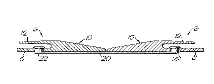
Figure 2 is a section through the holders of Figure
l along the line A-A;
Figure 3 is a section through the holders of Figurè
1 along the line B-B; and
Figure 4 is a perspective view of one embodiment of
the connection member of Figure 3.
Figure 5 is a plan view of a further embodiment of a
connecting member.
Figure 6 is a plan view of a mat holder,
incorporating the connecting member of
Figure 5; and
Figure 7 is a cross-sectional view along the line
VII-VII of Figure 6.
The figures show a number of mat holders 6, each of
which has a base 8 and side walls 10. ln use, a mat is
placed on the base 8, within the recess defined by the side
walls, and ~laps 12 resiliently close down over the edges
of the mat, so holding the mat in place.
A number o~ holes 14 are provided around the. edge of
the holder 6, beneath the flaps 12. Alternatively, a
recess 16 may be provided which extends for a substantial
fraction of a side of the holder. A connecting member,
which is further described below, fits into khe holes 14 or
the recesses 16.
one embodiment of the connecting member is shown in
Figures 1 and 2. The connecting member 18 consists of an
elongated body 20 having, at either end, a lug 22, each of
which fits snugly into adjacent holes 14 of two juxtaposed
holders 6, in order to hold the two holders together.

Another embodiment of the connecting member is ~hown
in Figures 1, 3 and ~. The connec~ing member 2~ consists
of a strip 26 having connecting means, in the fo~m of two
ridges 28, which extend ~or the length of the strip 26.
The length of connecting members 2~ is intended to be of
the same order of magnitude as the length of the edge of
the mat holder 6. This means that the connection between
two holders is firmer and stronger than with connecting
member 18.
Another embodiment of a connecting member for use with
a mat holder is shown in Figure S. The connecting member
30 has four lugs 32 and a plurality of elongated slots 34
which extend between the lugs. The slots 34 allow one end
o~ the connecting member 30 to move slightly, in the
direction shown by the arrow, relative to the other end.
The member 30 may also be provided with a tongue 36 at
either end, the purpose of which will be described
hereafter.
The lugs 32 of the connecting member 30 are intended
snugly to fit within holes 14 provided on the mat holder.
The member 30 requires two holes to be provided in the base
of the holder, as shown in Figure 6. The lugs may pass
through the base 8, as shown in Figure 2, or may fit with
holes 14 provided in the side walls 10 of the holder as
shown in Figure 7.
A slit 38 is provided in the base 8 of the holder,
adjacent the holes l~L and beneath the flap 12, to accept
the tongue 36 of the connecting member 30 as shown in
Figures 6 and 7. This serves to provide a stronger
connection between adjacent holders than would be provided
solely by the engagement of the lugs 32 by the holes in the
base of the holder.

Representative Drawing
A single figure which represents the drawing illustrating the invention.
Administrative Status

2024-08-01:As part of the Next Generation Patents (NGP) transition, the Canadian Patents Database (CPD) now contains a more detailed Event History, which replicates the Event Log of our new back-office solution.

Please note that "Inactive:" events refers to events no longer in use in our new back-office solution.

For a clearer understanding of the status of the application/patent presented on this page, the site Disclaimer , as well as the definitions for Patent , Event History , Maintenance Fee  and Payment History  should be consulted.

Event History

Description Date
Inactive: IPC from MCD 2006-03-11
Application Not Reinstated by Deadline 2001-12-13
Time Limit for Reversal Expired 2001-12-13
Deemed Abandoned - Failure to Respond to Maintenance Fee Notice 2000-12-13
Amendment Received - Voluntary Amendment 1998-06-10
Letter Sent 1998-01-26
Inactive: Status info is complete as of Log entry date 1998-01-26
Inactive: Application prosecuted on TS as of Log entry date 1998-01-26
Request for Examination Requirements Determined Compliant 1997-11-13
All Requirements for Examination Determined Compliant 1997-11-13
Application Published (Open to Public Inspection) 1991-06-16

Abandonment History

Abandonment Date Reason Reinstatement Date
2000-12-13

Maintenance Fee

The last payment was received on 1999-09-28

Note : If the full payment has not been received on or before the date indicated, a further fee may be required which may be one of the following

  • the reinstatement fee;
  • the late payment fee; or
  • additional fee to reverse deemed expiry.

Patent fees are adjusted on the 1st of January every year. The amounts above are the current amounts if received by December 31 of the current year.
Please refer to the CIPO Patent Fees web page to see all current fee amounts.

Fee History

Fee Type Anniversary Year Due Date Paid Date
MF (application, 7th anniv.) - standard 07 1997-12-15 1997-09-26
Request for examination - standard 1997-11-13
MF (application, 8th anniv.) - standard 08 1998-12-14 1998-09-24
MF (application, 9th anniv.) - standard 09 1999-12-13 1999-09-28
Owners on Record

Note: Records showing the ownership history in alphabetical order.

Current Owners on Record
KIMBERLY-CLARK LIMITED
Past Owners on Record
JOHN CALVERT
PHILIP MOGEL
Past Owners that do not appear in the "Owners on Record" listing will appear in other documentation within the application.
Documents

To view selected files, please enter reCAPTCHA code :


To view images, click a link in the Document Description column. To download the documents, select one or more checkboxes in the first column and then click the "Download Selected in PDF format (Zip Archive)" or the "Download Selected as Single PDF" button.

List of published and non-published patent-specific documents on the CPD .

If you have any difficulty accessing content, you can call the Client Service Centre at 1-866-997-1936 or send them an e-mail at CIPO Client Service Centre.


Document
Description 
Date
(yyyy-mm-dd) 
Number of pages   Size of Image (KB) 
Description 1998-06-09 4 171
Claims 1998-06-09 1 45
Abstract 1993-11-11 1 14
Drawings 1993-11-11 2 63
Claims 1993-11-11 2 45
Description 1993-11-11 4 164
Representative drawing 1999-07-13 1 7
Reminder - Request for Examination 1997-08-12 1 117
Acknowledgement of Request for Examination 1998-01-25 1 179
Courtesy - Abandonment Letter (Maintenance Fee) 2001-01-09 1 183
Fees 1996-09-23 1 79
Fees 1995-09-19 1 76
Fees 1994-09-20 1 84
Fees 1993-09-23 1 78
Fees 1992-09-24 1 74