Language selection

Search

Patent 2032188 Summary

Third-party information liability

Some of the information on this Web page has been provided by external sources. The Government of Canada is not responsible for the accuracy, reliability or currency of the information supplied by external sources. Users wishing to rely upon this information should consult directly with the source of the information. Content provided by external sources is not subject to official languages, privacy and accessibility requirements.

Claims and Abstract availability

Any discrepancies in the text and image of the Claims and Abstract are due to differing posting times. Text of the Claims and Abstract are posted:

  • At the time the application is open to public inspection;
  • At the time of issue of the patent (grant).
(12) Patent: (11) CA 2032188
(54) English Title: ILLUMINATED MARKER BUOY
(54) French Title: BOUEE LUMINEUSE
Status: Expired and beyond the Period of Reversal
Bibliographic Data
(51) International Patent Classification (IPC):
  • B63B 22/16 (2006.01)
  • B63B 45/00 (2006.01)
(72) Inventors :
  • SCHROEDER, HUGH I. (United States of America)
(73) Owners :
  • HUGH I. SCHROEDER
(71) Applicants :
(74) Agent: SMART & BIGGAR LP
(74) Associate agent:
(45) Issued: 1995-10-24
(22) Filed Date: 1990-12-13
(41) Open to Public Inspection: 1991-11-19
Examination requested: 1991-05-15
Availability of licence: N/A
Dedicated to the Public: N/A
(25) Language of filing: English

Patent Cooperation Treaty (PCT): No

(30) Application Priority Data:
Application No. Country/Territory Date
07/526,158 (United States of America) 1990-05-18

Abstracts

English Abstract


A spherical buoy of translucent plastic
material has a circular cutout leading to the open
interior of the buoy. A cylindrical insert having a
closed inner end portion and an open unobstructed
interior is inserted into the cutout. The outer end
portion of the insert is bonded to the margin of the
cutout. A self-contained battery-operated light is
actuated and inserted into the insert whereupon the
outer end of the insert is closed by a screw cap to
retain the actuated light in the insert. The insert is
of light transmissive material such that the buoy is
illuminated from the interior.


Claims

Note: Claims are shown in the official language in which they were submitted.

The embodiments of the invention in which an
exclusive property or privilege is claimed are defined
as follows:
1. A nautical marker buoy for receiving a
self-contained battery-powered light having a casing
supporting a bulb and containing batteries for powering
the bulb, said buoy comprising a hollow shell of
translucent material having a cutout, an elongated
insert having a closed inner end, an open outer end and
a continuous sidewall extending between said inner and
outer ends defining an unobstructed interior cavity
sized for reception of the entire self-contained
battery-powered light, said insert being secured in
said cutout of said shell with the inner end of said
insert received in the interior of said shell and the
outer end portion of said insert supported on said
shell, and cap means separate from said self-contained
battery-powered light for closing the open outer end of
said insert for enclosing and retaining the self-
contained battery-powered light therein but manually
detachable from said insert for removal of said self-
contained battery operated light in its entirety, said
insert being transmissive of light whereby, with said
light received in said insert and actuated, said shell
is illuminated by transmission of light through said
insert into the interior of said shell.
2. The buoy defined in claim 1, in which the
insert includes an elongated inner portion having the
closed inner end, an open outer end and the continuous
sidewall extending between the closed inner end and
said open outer end, said insert further including a
fitting having an open outer end and an inner end
forming an opening for closely receiving the sidewall
of said insert by sliding movement of said insert inner
portion into said fitting, said insert inner portion

being secured in said insert fitting and said fitting
being received in the cutout of the shell and being
bonded therein.
3. The buoy defined in claim 2, in which the
outer end portion of the insert inner portion has an
outward-projecting flange and the inner end portion of
the insert fitting having an inward-projecting lip,
said flange and said lip being engaged to limit
insertion of the insert inner portion into the insert
fitting.
4. The buoy defined in claim 2, in which the
outer end portion of the fitting has an outward-
projecting flange limiting insertion of the fitting
into the cutout of the shell.
5. The buoy defined in claim 4, in which the
fitting is bonded in the shell cutout by a friction
bond formed by spinning the fitting in the cutout.
6. The buoy defined in claim 3, in which the
fitting has internal threads and the outward-
projecting flange of the insert inner portion has
external threads mating with said internal threads of
the fitting.
7. The buoy defined in claim 6, in which the
sealing means includes a screw cap having an externally
threaded portion for mating with the internal threads
of the fitting for closing the open outer end of the
fitting.
8. The buoy defined in claim 7, in which the
screw cap has an outward-projecting flange overlying
the outer end of the fitting, and including a resilient
member interposed between and compressed by engagement
between said cap flange and the outer end of the

fitting for a watertight fit of the cap relative to the
fitting.
9. The buoy defined in claim 1, in which the
shell is substantially spherical and the inner end
portion of the insert is disposed approximately at the
center of the shell.

Description

Note: Descriptions are shown in the official language in which they were submitted.


2032188
ILLUMINATED MARKER BUOY
The present invention relates to nautical
buoys.
Nautical marker buoys having electric lights
are disclosed in the following U.S. patents:
No. 1,374,942, issued April 19, 1921 (Melvin);
No. 1,481,583, issued January 22, 1924 (Anundi);
No. 1,796,460, issued March 17, 1931 (Jackson);
No. 3,071,788, issued January 8, 1963 (Nelson);
No. 3,698,025, issued October 17, 1972 (Worobel).
10 As illustrated by the above patents, there have been
efforts to provide a practical illuminated nautical
marker buoy for a considerable length of time. The
buoys disclosed in the above patents have ballast or
are otherwise of specialized construction to maintain
the buoys and their lights in a desired orientation,
and more or less complicated internal workings or
specialized constructions in order that the electric
light can be incorporated in or supported by the buoy.
Patent No. 4,291,484, issued September 29,
1981, to Young discloses an illuminated fishing float
or bobber and in the "Description of the Prior Art"
refers to other such devices, but that patent does not
pertain to a nautical marker buoy.
The principal object of the present invention
is to provide a novel illuminated nautical marker buoy
of simple inexpensive construction but reliable and
durable over a long period of use and having familiar
standard components easily recognized, maintained and
repairable by fishermen and boaters.
In the preferred embodiment of the present
invention, the foregoing object is accomplished by
providing a nautical marker buoy for receiving a self-
contained battery-powered light having a casing
supporting a bulb and containing batteries for powering
the bulb, said buoy comprising a hollow shell of
4~

203~188
_ 2
translucent material having a cutout, an elongated
insert having a closed inner end, an open outer end and
a continuous sidewall extending between said inner and
outer ends defining an unobstructed interior cavity
sized for reception of the entire self-contained
battery-powered light, said insert being secured in
said cutout of said shell with the inner end of said
insert received in the interior of said shell and the
outer end portion of said insert supported on said
shell, and cap means separate from said self-contained
battery-powered light for closing the open outer end of
said insert for enclosing and retaining the self-
contained battery-powered light therein but manually
detachable from said insert for removal of said self-
contained battery operated light in its entirety, said
insert being transmissive of light whereby, with said
light received in said insert and actuated, said shell
is illuminated by transmission of light through said
insert into the interior of said shell.
In drawings which illustrate the preferred
embodiment of the invention,
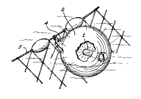
Figure 1 is a somewhat diagrammatic top
perspective of an illuminated nautical marker buoy in
accordance with the present invention secured to the
float line of a fishing net assembly; and Figure 2 isan enlarged fragmentary central transverse section of
such buoy.
With reference to the drawings, in accordance
with the present invention a cylindrical insert 1 is
incorporated in a hollow buoy 2 which preferably is of
translucent rigid plastic material. The buoy can be
approximately 18 inches in diameter and the insert
preferably extends about halfway into the buoy. Buoy 2
can have a projecting ear 3 with an eye 4 for easy
connection to the float line 5 of a fishnet assembly,
or for any other desired use for a nautical marker
buoy.

2032188
_ 3
As shown in Figure 2, the inner portion of
the insert 1 has a generally hemispherical closed
bottom 10 and a long cylindrical peripheral sidewall 11
leading to a top outward-projecting lip 12 having
external threads. Such threads mate with the internal
threads of a fitting 13 having an inward-extending
bottom annular flange or lip 14 for tight engagement by
the insert lip 12. Fitting 13 is snugly received in a
complementally shaped bore 15 through the translucent
generally spherical wall or shell 16 of the hollow buoy
2. Insertion of the fitting into the buoy is limited
by an outer annular flange 17 of the fitting engaged
against the exterior of the buoy shell 16.
Preferably the fitting and buoy are of
compatible meltable plastic materials such that the
insert 1 can be secured in the buoy by a friction bond
formed by rapidly spinning the fitting in the buoy bore
15 to achieve melting of the plastic material which
then solidifies for a permanent waterproof fit.
The open outer end of the fitting can be
closed by a screw cap 18 having an outer annular radial
flange 19 overlying the flange 17 of the fitting. A
resilient gasket or rubber O-ring 20 is interposed
between such flanges for an airtight and waterproof fit
when the cap 18 is screwed into the fitting.
Nevertheless, the cap 18 can be quickly and
easily removed, thereby exposing the open and
unobstructed interior of the insert 1. Such insert is
sized to receive a standard self-contained battery-
powered light having a casing 21 supporting a bulb 23and containing batteries for powering the bulb, such as
a standard self-contained marine light of the type
having a transparent dome 22 enclosing the bulb 23 for
radiation of light in all directions, as compared to
standard self-contained flashlights intended to shine a
beam of light generally axially away from the body of
the flashlight. The light sold under the trademark
"SCOTTY" available from Marine & Fishing Products of

2032188
_ 4
Victoria, British Columbia, Canada, is acceptable for
use in the present invention.
After actuation of the self-contained light
21, it can be quickly and easily fitted into the insert
and sealed therein by the cap 18. A resilient pad 24
can be interposed between the cap and the adjacent end
of the light to hold the light securely in position
with its bulb 23 at approximately the center of the
spherical buoy. When the buoy is retrieved, the cap
can be removed to turn off the light, or the light can
be of the type having a sensor so that power to the
bulb is automatically cut off during the daytime.
The improved buoy in accordance with the
present invention does not require specialized lights,
wiring or switches, but is adaptable to different types
of standard lights and, therefore, does not require
complicated construction or specialized maintenance.

Representative Drawing
A single figure which represents the drawing illustrating the invention.
Administrative Status

2024-08-01:As part of the Next Generation Patents (NGP) transition, the Canadian Patents Database (CPD) now contains a more detailed Event History, which replicates the Event Log of our new back-office solution.

Please note that "Inactive:" events refers to events no longer in use in our new back-office solution.

For a clearer understanding of the status of the application/patent presented on this page, the site Disclaimer , as well as the definitions for Patent , Event History , Maintenance Fee  and Payment History  should be consulted.

Event History

Description Date
Time Limit for Reversal Expired 2000-12-13
Letter Sent 1999-12-13
Grant by Issuance 1995-10-24
Application Published (Open to Public Inspection) 1991-11-19
All Requirements for Examination Determined Compliant 1991-05-15
Request for Examination Requirements Determined Compliant 1991-05-15

Abandonment History

There is no abandonment history.

Fee History

Fee Type Anniversary Year Due Date Paid Date
Reversal of deemed expiry 1997-12-15 1997-09-05
MF (patent, 7th anniv.) - small 1997-12-15 1997-09-05
MF (patent, 8th anniv.) - small 1998-12-14 1998-11-25
Owners on Record

Note: Records showing the ownership history in alphabetical order.

Current Owners on Record
HUGH I. SCHROEDER
Past Owners on Record
None
Past Owners that do not appear in the "Owners on Record" listing will appear in other documentation within the application.
Documents

To view selected files, please enter reCAPTCHA code :


To view images, click a link in the Document Description column. To download the documents, select one or more checkboxes in the first column and then click the "Download Selected in PDF format (Zip Archive)" or the "Download Selected as Single PDF" button.

List of published and non-published patent-specific documents on the CPD .

If you have any difficulty accessing content, you can call the Client Service Centre at 1-866-997-1936 or send them an e-mail at CIPO Client Service Centre.


Document
Description 
Date
(yyyy-mm-dd) 
Number of pages   Size of Image (KB) 
Description 1995-10-23 4 169
Abstract 1995-10-23 1 20
Claims 1995-10-23 3 96
Abstract 1995-10-23 1 19
Drawings 1995-10-23 1 40
Representative drawing 1999-07-21 1 16
Maintenance Fee Notice 2000-01-09 1 178
Fees 1996-09-10 1 74
Fees 1995-07-25 1 64
Fees 1994-10-03 1 59
Fees 1993-09-09 1 41
Fees 1992-08-25 1 36
Prosecution correspondence 1990-12-12 3 116
Prosecution correspondence 1991-05-14 1 22
Courtesy - Office Letter 1991-08-22 1 21
Correspondence related to formalities 1995-08-20 2 41