Note: Descriptions are shown in the official language in which they were submitted.
- 1 -
9-18225/=/GSY 558
METI-IOD AND APPARATUS FOR CHECKING
FILM-CUTTING POSITIONS
This invention relates to cutting photographic film into strips for insertion
into envelopes and, more particularly, to a method and apparatus for sensing
film
density so as to prevent cutting the film through an exposed frame.
In amateur photography, most film processing is accomplished in large,
automatic batch-processing labs to help hold down developing costs and reduce
turnaround times. Individual rolls of undeveloped film are spliced together to
form large rolls of film for batch processing. As the film is processed, a
notcher
locates the exposed frames and notches an edge of the film near each detected
frame. Printing equipment uses the notches to position each frame before print-
ing the frames on photographic paper. Prior to redelivery of the processed
film to
the customer, the film is cut into strips. A film cutter senses the notches as
a
means of positioning the film to the proper cut location. As the film advances
through the cutter, the notches are counted. After a predetermined number of
notches has been sensed, the film has been advanced an appropriate distance so
that, ideally, the film cutter cuts the film in the unexposed area between
adjacent
exposed frames.
One problem associated with automated batch-processing labs is that, if for
any reason the notches are not located in proper relation to the exposed
frames,
the film cutter may cut the film in the wrong location. There are numerous
reasons why the notcher might place a notch in a wrong location, including,
for
example, operator error in setting up and adjusting the notcher or a component
failure in the notcher that causes the notcher to be out of calibration. In
any
event, misplaced notches may cause the film cutter to cut the film through an
exposed frame, thereby irretrievably damaging that frame. Obviously, the conse-
- 2 -
quences of such an error are unpleasant and will most likely subject the
processing
lab to customer complaints and a loss of future business from that customer.
As can be readily appreciated from the foregoing discussion, there is a need
in a film-processing operation for preventing a film cutter from cutting film
in a
predetermined cut location that erroneously lies in an exposed frame. This
inven-
tion is directed to a method for achieving these results and an apparatus for
carrying out the method.
In accordance with the present invention, a method for checking film-cutting
positions is provided. The method includes the steps of sensing a base density
of
the film, sensing a film density at a predetermined cut position of the film,
com-
paring the base density of the film and the film density at the predetermined
cut
position, and producing a cutter control signal that causes a film cutter to
cut the
film at the predetermined cut position only if the film density at the
predeter-
mined cut position is within a predetermined range of the base density of the
film.
In accordance with further aspects of the present invention, the method
further camprises the steps of continuously sensing 'the density of the film
and
producing film density data whose values are related to the density of the
film
sensed, selecting a data value indicative of the lowest film density and
producing
this data value as base density data fox the film, producing cut position
density
data whose value is related to the film density at the predetermined cut
position,
and comparing the base density data and the film density data at the predeter-
mined cut position.
In accordance with still further aspects of the gresent invention, the method
includes keying the base density data to a particular roll of film. This step
in-
cludes detecting a splice at a first time indicative of an end of the base
density
data for a first roll of film and detecting the splice at a second time,
subsequent
to the first time, indicative of a start of the base density data for a second
roll of
film.
In accordance with the present invention, an apparatus for carrying out the
cut position verification method described above is provided, The apparatus
Includes a first density sensor that senses film density of the film at a
plurality of
locations and produces film density data related to the film densities sensed.
A
second density sensor senses film density at a predetermined cut position and
produces cut position density data whose value is related to the film density
at the
predetermined cut position, A base density selector selects a data value
indica-
tive of the lowest film density and outputs this value as base density data
whose
value is related to the base density of the film. A comparator compares the
base
density data and the cut position density data and produces a cutter control
signal
that causes a film cutter to cut the film at the predetermined cut position
only if
the cut position density data shows that the density at the predetermined cut
position is within a predetermined range of the base density.
In accordance with still further aspects of the invention, the base density
selector includes first and second splice detectors. The first and second
splice
detectors are used to determine the beginning and end of successive film
orders so
that the base density data can be updated for each new film order.
As will be appreciated from the foregoing summary, the invention provides a
method for checking film-cutting positions by comparing the film density at a
predetermined cut position with the base density of the film and permitting a
film
cutter to cut the film only if the film density at the predetermined cut
position is
within a predetermined range of the base density of the film. Further, an
appara-
tus is provided for carrying out this method.
The foregoing and other features and advantages of this invention will
become more readily appreciated as the same becomes further understood by
reference to the following detailed description when taken in conjunction with
the
accompanying drawings wherein:
Fig. 1 is a block diagram depicting the bro~~d, functional aspects of
the present invention; and
Fig. 2 is a block diagram of a preferred embodiment of the invention
illustrated in Fig. 1.
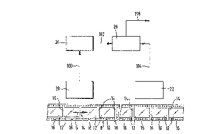
F~.g. 1 illustrates the broad features of the present invention. In a
batch operation, individual rolls of film are spliced together to form a
continuous film web 8 that is advanced through the several stages of the
processing operation. In Fig. 1, the film web 8 is illustrated as moving
from left to right, as indicated by an arrow 9. The film web 8 contains
exposed frames 12 located along its length, which are separated by unexpo-
sed spaces.l4. The density (i.e., the optical density) of the film web 8
varies significantly between the unexposed spaces 14 and exposed frames 12.
Typically, the density of the unexposed spaces 14 is substantially less
than the density of the exposed frames 12 even though the density of dif-
ferent exposed frames 12 may, and typically does, vary significant-
- 4 -
ly. The lowest density value of the film web 8 is hereinafter referred to as
the
base density of the film.
In a conventional manner, notches 16 are cut along an edge 18 of the web 8.
The notches 16 are cut by a notcher, which is not shown and does not form part
of
the present invention. Different types of notchers, all of which are well
known in
the photographic film-processing art, place a notch 16 in a particular
location
adjacent each frame 12. The relative location of the notches 16 with respect
to
the adjacent frames 12 may vary between the different types of notchers, but
the
relative locations are the same for any one type of notcher. For purposes of
simplicity, the notches 16 shown in~Fig. 1 are centered along each frame 12.
It is to be understood, hawever, that the present invention works equally well
with
notches 16 placed in other locations relative to the exposed frames 12.
Once the notches 16 have been cut into the web 8, they, in part, control the
processing operation. For example, a film cutter (also not shown in Fig. 1 and
also not part of the present Invention) cuts the web 8 into strips whose
length is
determined, in part, by a predetermined number of notches 16. That is, once
the
processing equipment senses the passage of a predetermined number of notches
16, 'the film cutter cuts the web 8. More specifically, once the predetermined
number of notches 16 has been sensed, the film web 8 is advanced a fixed dis-
tance. This fixed distance positions the film so that the film cutter cuts the
web 8 in a predetermined cut position. Ideally, the predetermined cut position
lies
in an unexposed space 14 between adjacent frames 12. The distance the film is
advanced after the predetermined number of notches 16 has been sensed is de-
pendent upon the type of notcher used in the processing operation. That is, if
the
notch 16 is located along the center of the frame 12, as shown in Fig. 1, the
processing equipment is programmed to move the film a certain distance so as
to
position the next unexposed space 14 at the cutter. As can be readily
appreciated
by one of ordinary skill in the photographic film-processing art, when the
notches
16 are placed in the wrong location, due to the notcher being out of
calibration,
for example, the film may very likely be advanced so that the predetermined
cut
position does not lie in an unexposed space 14 but, rather, in an exposed
frame
12. As will become better understood from the following discussion, the method
and apparatus of the present invention are designed to doublecheck the
predeter-
mined cut position and prevent the cutter from cutting the film through an
exposed frame 12.
- 5 -
As illustrated in Fig. 1, the apparatus of the present invention in-
cludes density sensors 20 and.22, a base density selector 24, and a compa-
rator 26. The distance between the tc~ density sensors must be smaller
than the distance between two consecutive splices._The
first density sensor 20 senses film density at a plurality of locations as the
film
web 8 passes the density sensor 20. Preferably, the first density sensor 20
contin-
uously senses the film density: In the illustrated embodiment, density sensor
20
produces film density data on line 100 having values related to the sensed
film
densities. The base density selector receives the data on line 100, selects a
data
value indicative of the lowest film density, and outputs this value as base
density
data on line 102. In a manner that will be discussed more fully below, the
second
density sensor 22 senses film density at a predetermined cut position and
produces
cut position density data on line 104. Again, in the illustrated embodiment,
the
data on line 104 has a value related to the film density at the predetermined
cut
location. The comparator 24 compares the data on lines 102 and 104 and
produces
a cutter control signal on line 106. The cutter control signal, in part,
controls a
film cutter (not shown). If the data on lines 102 and 104 indicates that the
density
read by the second density sensor 22 is equal to, or within a predetermined
range
of, the base density determined by the base density selector 24, the cutter
control
signal will cause the cutter to cut the film web 8. If, however, the data on
lines
102 and 104 indicate that the film density at the predetermined cut position
is nat
within the predetermined range, e.g., where the film density at the
predetermined
cut position is substantially greater than the base density, the cutter
control
signal will prevent the cutter from cutting the film web 8, since the
possibility
exists that the cut position is in the area of a high-density exposed frame
12.
Fig. 2 Is a block diagram illustrating, in more detail, a preferred embod-
iment of the invention depicted in', Fig. 1 and discussed above. As noted
above, the density data values on lines 102 and 104 are related to the
appropriate _
film densities. As will become better understood from the following
discussion,
the density data values in the preferred embodiment depicted in Fig. 2 are
directly proportional to the film densities. However, it will be clear to
those of
ordinary skill in the art that the electronics could be engineered to use a
different
relationship between the density and the density data with equally successful
results. For example, the density data could be inversely proportional to the
film
density.
- 6 -
The first density sensor 20 is an optical sensor and includes a first transmit-
ter 30, a first receiver 32, and an analog-to-digital (A/D) converter 36. A
beam of
light, or light signal, 34 is transmitted by the first transmitter 30 and is
directed
toward the film web 8. The light signal 34, after passing through the film web
8,
is detected by the first receiver 32. The strength of the received light
signal 34 is
a function of the density of the film web 8 through which it passes. More spe-
cifically, the strength of the light signal 34 that passes through higher
density
portions of the film web 8 is lower than the strength of the light signal 34
that
passes through a lower density portion of the film web 8. Accordingly, less
light
will reach the first receiver 32 when the light signal 34 passes thzough an
exposed
frame 12 (i.e., a higher density portion of the film web 8) than when the
light
signal 34 passes through an unexposed portion of the film web 8, such as a
space
14 (i.e., a lower density portion of the film web 8). As a result, the
strength of
the received light signal 34 is inversely proportional to the transmission
of the film web 8 through which it passes. It is well understood
that the density is given by the negative logarithm of the transmission.
Tn response to the received light signal 34 the first receiver 32 produ-
ces an electric signal on line 108 whose magnitude is related 'to
the density of the film portion through which the light signal 34 passes.
As noted above, the first sensor 20 preferably continuously senses the den-
sity of the film web 8 as it passes by the sensor 20. Further, the signal on
line 108
is an analog signal. The A/D converter 36 converts the analog signal on line
108
to a digital signal and produces the film density data on line 100, as noted
above.
The second sensor 22 is also an optical sensor and similarly includes a second
transmitter 40, a second receiver 42, and an A/D converter 46. The second
sensor
22 is preferably positioned near the film cutter (not shown) so that the
second
sensor 22 senses film density of the film web 8 at a predetermined cut
position. A
beam of light, or light signal, 44 is transmitted by the second transmitter 40
and is
directed toward the film web 8. The light signal 44, after passing through the
film
web 8 at the predetermined cut position, is received by the second receiver
42.
The strength of the received light signal 44 is inversely proportional to the
density
of the film web 8 sensed by the sensor 22. The receiver 42 produces a film
density
signal on line 116 and, more particularly, a cut position density signal
correspond-
ing to the density of the film at the predetermined cut position on the film
web
8. In response to the received light signal 44 the magnitude of the cut
position
density signal is related to the strength of the received light signal 44 and
to the
density of the film. The A/D converter 46 converts the signal on line 116 from
an
analog signal to a digital signal and produces the cut position density data
on
line 104, as noted above.
In accordance with the preferred embodiment of the present invention, the
light signals 34 and 44 consist of visible light energy. Other forms of light
energy,
such as infrared or ultraviolet energy, are typically not well suited for
determin-
ing film density. For example, both the exposed and unexposed portions of the
film web 8 appear transparent under infrared light and opaque under
ultraviolet
light. Further, the A/D converters 36 and 46 have been discussed above as form-
ing a part of the respective density sensors 20 and 22. Such a grouping of com-
ponents was done for the purpose of understanding and discussing the present
invention. It is to be understood, however, that in an actual physical
embodiment,
the A/D converters 36 and 46 may be separate from the sensors 20 and 22. Fur-
ther, in accordance with the preferred embodiment of the present invention
illustrated in Fig . 2 , the density data values produced on lines 100 and 104
are
directly proportional to the corresponding film densities. However, it is to
be
understood that the method and apparatus of the prf;sent invention work
equally
well with other relationships between the film density and density data
values.
'fhe base density selector 24 includes data storage devices 50 and 52 and
splice detectors 54 and 56. The splice detectors 54 and S6 will be discussed
in
more detail below. The first data storage device 50 receives and stores the
film
density data on line 100 and produces an output, in the form of film density
data,
on line 110. The first data storage device 50 also operates as a latching
device
that updates the output on line 110 each time a lower film density data value
is
received on line 100. That is, the first data storage device 50 selects the
lowest
value of the film density data on line 100 and outputs this value on line 110.
The
second data storage device 52 reads and stores the output from the first data
storage device 50. As will be discussed more fully below, the data stored in
the
second data storage device 52 is updated at appropriate times and produced as
the
base density data on line 102, as noted above.
As is well known in the photographic film-processing art, individual rolls of
film are spliced together to form the continuous film web 8 for batch
processing.
The continuous film web 8 aids in reducing both processing costs and
processing
times of the individual rolls. The individual rolls of film are typically
spliced
together at adjacent ends with splice tape. As can be seen int Fig . 2 , a
portion
of the film web 8 includes a first roll of film 10 and a second roll of film
11
spliced together at their ends by a piece of splice tape 60. Specifically, a
trailing
edge 62 of the first roll of film 10 is spliced to a leading edge 64 of the
second roll
of film 11. Typically, the splice tape 60 is substantially opaque and, hence,
opti-
cally much denser to light signals than either the exposed frames 12 or
unexposed
spaces 14. The significance of the splice tape's high density will become
evident
from the following discussion.
Because different rolls of film may very likely have different base densities,
it is important to determine the base density for each particular roll of
film. That
is, the base density data values should be keyed to each respective .roll of
film.
This is accomplished in the present invention, in part, by providing splice
detec-
tors 54 and 56, briefly noted above. The splice detectors 54 and 56 may be
thought of as comparators that compare the magnitudes of the signals on their
input lines to predetermined threshold values. Preferably, the only time the
signal
magnitudes on the input lines to the splice detectors 54 and 56 are less than
the
threshold values is when the splice tape 60, which, as noted above, is
substantially
opaque, is sensed by the sensors 20 and 22. Accordingly, the splice detectors
54
and 56 will switch states when the splice tape 60 is sensed. Thus, the splice
tape
60 may be used to indicate the beginning and ending of a particular roll of
film,
such as the roll of film 10 311ustrated in Fig. 2.
A first splice detection transmitter 31 is located in close proximity to the
first transmitter 30. In fact, in most situations the first transmitter 30,
first
receiver 32, first splice detection transmitter 31, and a first splice
detection
receiver 33 will all be part of a signal optical sensor module. The first
splice
detection transmitter 31 produces a light signal 35 that passes through the
film
web 8 and is received by the first splice detection receiver 33. When the
splice
tape 60 passes between the first splice detection transmitter 31 and the first
splice detection receiver 33 the light path is essentially blocked and the
magni-
tude of the signal on line 109 to the first splice detector 54 drops below the
g
threshold value. As a result, the splice detector 54 switches states and
produces
outputs on lines 112 and 114. The output on line 114 is a reset signal that
causes
the first data storage device 50 to reset, thus indicating an end of the
density data
for the roll of film 10. Concurrently, the output on line 112 is a stop signal
that
causes the second data storage device 52 to stop reading outputs on line 110,
thus
indicating that subsequent data values on line 110 are for the next roll of
film 11.
As the film web 8 continues to advance (i.e., from left to right in Fig. 2) ,
the splice tape 60 passes between a second splice detection transmitter 41 and
its associated second splice detection receiver 43. The splice tape 60 blocks
the
passage of light beam 45, thereby decreasing the signal from second splice
detec-
tion receiver 43 on line 117 to the second splice detector 56. When the
magnitude
of the density signal on line 117 drops below the threshold value, the splice
detec-
tor 56 switches states and produces an output on line 118. The output on line
118
is a start signal that causes the second storage device 52 to resume reading
data
on line 110, i.e., the base density data for the next roll of film 11.
As noted above, the purpose of the present invention is to verify that a
predetermined cut position lies in an unexposed portion of the film web 8 and
to
prevent the film cutter from cutting the film web 8 through an exposed frame
12. To accomplish this, the second sensor 22, as noted above, senses the film
density at a predetermined cut position. As illustrated in Fig . 2 , the com-
parator 26 is controlled by a contral signal on line 1 S?0. The signal on line
120 is
irelated to the advancement of the film web 8. 'the signal on line 120 may,
for
example, be produced by a counter 66 that counts pulses produced by a film
drive,
such as a stepper motor, which advances the film web 8. In a conventional
manner, the stepper motor produces pulses on line 122. A predetermined number
of pulses is produced between successive predetermined cut positions.
According-
ly, these pulses can be counted, and when the predetermined number of pulses
has
been counted, the counter 66 produces the control signal on line 120. Thus,
the
control signal on line 120 causes the comparator to compare the current base
density data value on line 102 with the cut position density data on line 104
and
the cutter control signal on line 106, as noted above.
As also noted above, in the preferred embodiment of the invention, the
density data values are directly proportional to the corresponding film
densities.
- 10 -
Accordingly, if the cut position density data on line 104 is greater than the
base
density data on line 102 (which indicates that the cut position density is
greater
than the base density), there is a possibility that the predetermined cut
position
lies in an exposed frame 12, in which case, the cutter control signal on line
106
will not permit the film cutter to cut the film 10.
As can be readily appreciated from the foregoing description, the invention
provides a method and apparatus for checking cutting positions by sensing film
density and permitting a film cutter to cut the film only when a predetermined
cut position lies in an unexposed portion of the film. While a preferred
embodi-
ment of the invention has been Illustrated and described herein, it is to be
under-.
stood that, within the scope of the appended claims, various changes can be
made. Since the invention may be practiced otherwise than as specifically de-
scribed herein, the invention is to be defined solely with reference to the
claims
that follow.