Note: Descriptions are shown in the official language in which they were submitted.
2~ ~ J ~
REFRI&ERATION SYSTEN WITH MASS FLOW LIMITING D~ICE
In its simplest form a closed refrigeration system, such as is
used in transport refrigeration equipment, serially includes a
compressor, a discharge line, a condenser, an expansion device,
an evaporator and a suction line connected to the compressor. In
such a system, the mass flow, which is gsnerally proportional to
the suction pressure, is indicative of the compre.s~or power
requirements~ In normal operation, the suction gas is in the
form of a low pressure superheated vapor and its state is
dependent upon a number of factors such as ambient temperature,
the temperature being maintained and whether the system has
reached equilibrium or is still heing pulled down. At startup,
the suction gas may be at ambient temperature and even partially
condensed in the evaporator and suction line. Under these
conditions, and especially during conditions of pulldown, the
mass flow of refrigerant drawn into the compressor and
subseguently compressed is much greater than it would be in an
equilibrium situation. This greater mass flow results in
significantly increased power requirements. During operation,
the mas~ flow rate will change with ambient temperature and other
variations in the heat load on the space being refrigerated such `
as the exposure of a refrigerated cargo container to sun load.
Refrigeration systems that see a wide variation in air
temperatures over the condenser and evaporator coils experience a
correspondingly large variation in suction pressure and mass flow
rate of the refrigerant, resulting in a wide variation in the
power requirements of the compressor. A transport refrigeration
system i5 an example of this. Cargo requirements can range from
55F for bananas to -20F for ice cream, and ambient temperatures
can range from -20F to 120F. There are, in addition, operating
factors such as having to pull down the temperature of cargo
loaded at a temperature greater than the desired setpoint, and
size and weight limitations on the system components, which
result in instances where the mass flow rate and pressure of the
suction gas returning to the compressor, if not regulated, would
overload the engine which drives the compreslsor.
A properly designed mass flow limiting device is located in the :
compressor suction line of a re~rigeration s~ystem~ Proper design
requires consideration of the desired limits of suction pressure
and mass flow as well as the type of refrigerant being used. The
device includes a variable flow restriction whosa position is
responsive to khe differential fluid pressure across the
restriction plus a spring bias. Movement of the variable flow
restriction achieves a relatively constant downstream pressure
and thereby limits the mass flow. However, the variable ~low
restriction only changes the cross section of the flow path after
a predetermined pressure drop is achieved.
~asically, the mass flow of suction gas supplied to the inlet of
the compressor of a refrigeration system is limited to prevent
overloading the engine or motor which powers the compressor.
Since the mass flow is generally proportional to the pressure of
the gas, an increase in the suction pressure upstream of the
device beyond a predetermined value tends to cause it to move to
a position restricting the flow and this movement is opposed by
the suction pressure downstream of the device plus a spring bias.
This coaction maintains a relatively constant suction pressure
downstream of the device thereby limiting the mass flow.
Figure 1 is a schematic diagram of a refrigeration system
employing the present invention;
Figure 2 is an isometric view of the mass flow limiting device;
~ :,
~ ~ 3 ~
,.. , :
Fi~ure 3 is a partially cutaway isometric ViPW of the mass flow
lim.iting device;
~igure 4 is a ~ectional view of the mass flow limiting device;
Figure 5 is a top view of a portion of the central me~ber; and
Figure 6 is a sid~ view of a portion of the central member.
In Figure 1, the numeral 10 generally desi~nates a refri~eration
system such as a truck/trailer unit driven by an internal
combustion engine 12. Driven by engine 12, compressor 14
compresses the refrigerant thereby raising its temperature and
pressure and forcing tha refrigerant to ~low through discharge
line 16 to condenser 18 where the refrigerant is forced into the
condenser tube~ (not illustrated)O Heat is removed from the
refrigerant in the condenser 18, and the refrigerant liquifies. :~
The high temperature, high pressure liquid refrigerant flows via
line 20 to expansion device 22 such as a thermostatic expansion
valve which reduces the pressure of the liquid refrigerant and : :
meters the flow of liquid refrigerant to evaporator 26 via line
24. The reduction in pressure in expansion device 22 is ~ ~:
accompanied by a drop in temperature so that the low temperature,
low pressure liquid refrigerant supplied to the evaporator 26 is
colder than the air circulated over the evaporator tubes (not
illustrated). Thus, heat is removed from the air circulated over
the evaporator 26 and the resultant cold air is circulated, for
example, throughout a box to maintaln the cargo at the desired
temperature. The transfer o~ heat from the air to the low
temperature refrigerant in the evaporator 26 causes the liquid
refrigerant to vaporiæe. The resultant low temperature, low
pressure superheated vapor refrigerant is supplied via line 28 to
compressor 14. According to the teachings of the present
invention, a flow limiting device 30 is placed in the line
.
~ ~ 3 ~
between evaporator 26 and compressor 14, and is connacted thereto
via lines ~8 and 3~, respectively.
The function of flow limiting device 30 is to limit the mass flow
of refrigerant to compressor 14 to prevent the overloading of
engine 12 during those conditions in which excessively high mass
~low rates would otherwise result. Overloading is the result o~
compressing more mass of refrigerant per stroke of the compressor
than the compre~sor and its powar source are designed to handle.
However, under equilibrium conditions the flow limiting device 30
should have minimal influence on the system 10 since it is
designed fox the correct response for the refrigerant used and
specific system parameters.
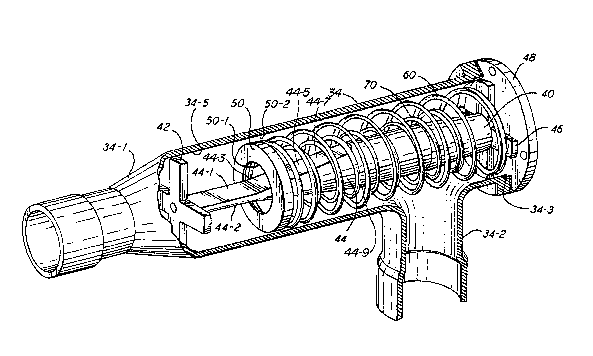
Referring now to Figures 2-4, flow limiting device 30 includes a
generally cylindrical housing portion 34 having a frustoconical
transition portion 34 1 adapted to be connected to line 28 and a
side passage 34-20 Within cylindrical housing portion 34 and
co-extensive therewith is a central member 40 having up~tream and
downstream cruciform end pieces 42 and 46, respectively, integral
with elongated axial member 44 which is located in cyli:ndrical
housing portion 34 by end pieces 42 and 46. Specifically, a
shoulder 34~3 is formed in housin~ 34 and coacts with the ends of
the arms of cruciform end piece 46 and end plate 48 to secure
central member 40 axially and radially in bore 34-5 of housing
34. Cruciform end piece 42 serves to keep annular member 50 on
central member 40 and helps to maintain central member 40
centered in bore 34~5. Elongated axial member 44 is of a varying
cross section in the axial direction with the cross section ~eing
the least at the upstream portion and then increasing in the
downstream direction for at least a portion of its length. In
the preferred embodiment illustrated, axial member 44 is
generally cylindrical with two symmetrically located uniform
portions 44-1 and 44-2 formed therein at the upstream end and
2 ~ 8
multiple symmetrical tapering portions 44-3 through 44-8 ~ormed
downstream of uniform portions 44-1 and 2 as is best shown in
Figures 5 and 6. Referring spacifically to 'Figure 6, it will be
noted that the uni~orm portions A4-1 and 2 transition into
tapering portions 44 3 and 44-4, respectively, and these, in turn
transition into tapering portions 44-5 and 6, respectively, which
have a different taper. Similarly, tapering portion 44-5 and 6
transition into tapering portions 44-7 and 8, respectively, which
have a different taper. Annular member 50 is located on axial
member 44 with coiled spring member 60 located on axial member 44
between annular member 50 and end piece 46. Spring member 60
normally biases annular member 50 so as to cause it to be located
at or near the upstream end of cylindrical housing portion 34 to
the extent permitted by end piece 42 and/or the unstressed length
of spring member 60 so that the resulting flow area defined by
opening 50-1 and member 44 is relatively large due to the uniform
portions 44-1 and 2. A second spring 70 is located on axial
member 44 but is of a shorter length than spring 60. As
illustrated in Figures 3 and 4, the annular member 50 engages
second spring 70 in the vicinity of the transition from unifoxm
portions ~4-1 and 2 to tapering portions 44-3 and 4. In addition
to the flow area defined by opening 50-1 and member 44, there is
a second annular flow area 50-2 defined between the outer
circumference of annular member 50 and the inner sur~ace of bore
34-5~
In operation, the upstream psrtion of annular member 50 is acted
on upon the pressure in line 28 which represents the pressure o~ :
the suction gas available to be supplied to the suction side of
the compressor 14. The downstream portion of annular member 50
is acted upon by the pressure in lin~ 32 which is the actual
pressure of the gas supplied to the suction side of the
compressor 14 plus the bias force of spring 60. At any given
position of annular member 50 on axial member 44, if changes to
~3~
the system 10 cause an increase in the upstream pre~sure and ~as~ :
flow rate, then the pressure differential across the flow areas
defined by openings 50-1 and 50-2 will increase. As the pressure
diferential increases, the annular member 50 moves downstream in
opposition to the bias of spring 60 which increases as it
compresses until a balance is again reached. When spring 60
compresses suf*iciently, spring 70 will be engaged and contact
both annular member 50 and end piece 46 so that there will be a
different spring rate for further pressure d:ifferential
increases. As the annular member 50 moves downstreaml th~
opening 50-1 initially coacts with uniform portions 44 1 and 2 so
that the cross sectional area of the flow path through opening
50-1 remains constant until the opening 50-1 coacts with tapering
portions 44-3 and 4 so as to decrease the flow area which reduces
the flow as well as increases the pressure dif~erential across
member 50. As opening 50-1 coacts with different ones of the
tapering portions 44-3 through 44-8, the response changes due to
the change in the angles of slopes of tapering portions 44-3
through 44-8. The multiple tapering portions more closely
maintain a constant suction pressure downstream of the device.
In addition, a stop 44-9, in the nature of a shoulder, is
incorporated into axial member 44 to limit the downstream
movement of annular member 50 to prevent compressing springs 60
and 70 beyond their elastic limits. As best shown in Figure 5,
it will be noted that annular member 50 would engage stop 44-9
prior to the reaching of the downstream ends of tapering sections
44-7 and 44-8. As the device adjusts, the pressure in line 28
will gradually reduce permitting annular member 50 to move
upstream to increase the flow area, thus permitting refrigeration
system 10 to reach a state of equilibrium with optimal power
consumption.
Although the present invention has been described in terms o~ an
internal combustion engine driven system, it is equally
-` 2~32~8
applicable to an electric or dual powered sy~temO Also, the bia~
on member 50 may be provided by any suitable device which
provide.s a Porce proportional to the displac:ement o~ member 50
with re~pect to member 44. It is therefore intended that the
present invention i~ to be limited only by the scope o~ the
appended claims.