Note: Descriptions are shown in the official language in which they were submitted.
2 ~ .~ 2 ~
Process an~ Equ~pment To Determlne ~i5turbance Varlabl~3 ~lhen Pourln~
Molten Metal From ~ Container
The inventi~n re]ates to a proce5s to determine disturbance v3riables
wnen pouring molten metal from a container having an outlet ~hannel and
related equipment. When pouring molten metal~ disturoance varlables
occur primarily in the form of vorte~, discharge of slag, blockages in
the outlet channe~ and/or due to defective, refraetory material forming
the outlet channel.
ln known processes of publication ~WO-Al 8~fO2583), in particular to
detect slag in steel melts, voltages that are evaluated
frequency-selectively are induced by means of the transmitting and
receiving coil enclosing the stream of metal melt without makinq
contact. The distribùtion of conductivity over the cross-section of flow
and from that the proportion of slag in the passing metal melt is~
determined from the frequency analvsis of said voltage~. In addition to
this, measurements of the changing temperature of the melt and the
measuring sensDrs are performed that are coupled to measured values of
the induced voltage spectrum. Since said transmitting and recqiving
coils are subject to intensive heat, on the one hand~ they wear
relatively rapidly, and, on the other hand, incidences that disturb
normal operation cannat, therefore, be ruled out. In addition to this,
this methad of measurement is time-consuming and, therefore, also not
reîiable.
The object of the present invention is to design a process and equipment
of the aforementioned kind in such a manner that with said process
disturbance variables can be determined reliably and quite simply.
The invention solves the problem in that vibrations qenerated by means
of the melt flowing on the container, respectively on its connecting
parts on the lip, are measured and disturbance variables are detected
froniany deviatjons from a desired vibrational characteristic.
.,
In this manner disturbances during pDuring can be determined early,
and thus the efficiency during pouring can also be increased.
'~
: :~ :. :.
2 ~ c r ~
~t the end Df the po~1r when the conta~ner i; almost empty~ tne
~ibrational characteristic 5hows an aDrupt variation ~ith re5~ect t~ the
desire~ ch3racteristic from ~hich the discharge of molten metal is
immediatelY stapped or after a pre-set period of time. rhus a pourinq Ot ~ '~~laa can oe avoided with certaintY and at the same time the residual
melt remaining in the contajner can be reduced to a mlnimum. In a
similar manner other disturban~e var1able5 such as blockaaes in the
outlet channel or the like can be determined.
The equipment of the inYention to carry out the prDcess has a
vibration measuring device on the container andlor on a cannectinq part
on the container lip. Said measurinq device permlts disturbance
variables to be detectèd at a distance from the melt radiating quite
intensive heat.
Other advantages and an embodjment Df the invention are explained in
deltail with reference to the drawing.
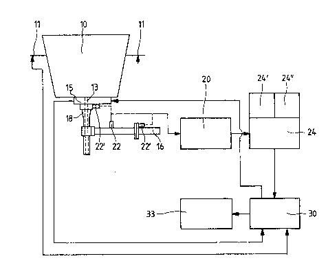
Figure i is a schematic presentation of equipment of the invention on acontainer containing metal melt.
Figure 2 is a diagram of the vibrational characteristics as a function
of time, illustrated at the end of the paur.
Fig. 1 shoKs a container lO containing metal melt; said contalner can
be, for exa0ple, a ladle containing steel melt or a tundish for
continuous casting. At its suspension points 11 weighinq cells to
measure the weight of the cDntainer are provided that send a signal to a
process cantrol computer 30. ~t the lip of the container IO i5 a closing
member 15, which serves to pour the quantity of melt in a controlled
manner and which is designed as a slide gate nozzle in the illustrated
case. ~ pouring pipe 18 that is held in posltion by a holding device 1~
and from which the metal melt flows, for example, into a mould ~hen the
qate lS is open, is adioined to this gate 15 50 as to seal. The
container IO and the aforementioned connectinq parts 15. 18 at the lip
are made of refractory material in the regiDn that makes contact w~th
the liquid melt.
. . ''
The mechanical vibrations caused by the stream of the metal ~elt flowing
on the container IO and on its csnnectinq parts 15, 16, 10 are measured
4 ;
: ~. '',~'.
2 ~
by a vibration measuring device 22 in which a cDnventinnal. so-called
- ple-o-electric accelerometer can be used. The measurinq device 72 is
mounted on the pouring pipe holding device 1~ in a vertical nr
horizontal direction 50 as to be detachable. ~f course, it could also be
mounted direct~y on the pouring pipe 18, at the gate ~S and/or also on
the container, as indicated with the measuring devices 22 . ~ maunting
on the pouring pipe changing device Ih has the advantage that when
changing the container 10, this device 2~ and its connecting lead to the
measurement processor 20, 24 can be left and consequently when changinq
the ladle there is no need for additional assembly or disassembly work.
The electrical signals of the vibrational amplitude y, measured by the
measuring device 22, are fed to a process control computer 30 from an
amplifier 20 via a filter ~4! which has a high pass 24 and a low pass
filter 24 . This process cantrol camputer 30 recDrds the measured
signals. It compares the vibratinnal characteristic ~ith a desired
vibrational characteristic, frDm which disturbance variables are
detected and, when possible disturbances occur, an alarm signal 33
and/or closing member or Pther means are activated.
8y means of the weight measurement 11 of the container 10 a signal is
fed to the computer 30; from which signal said computer knows how much
melt the container still contains. ~t the end of the pour the weight
determination is used as a support to detect the outflow of slag. The
actual detection of a vortex ~eddy formation in thæ bath) and outflow
of slag i5 performed by measuring the vibrational characteristic, as
shown in Fig. ~. The actual characteristic 40 of the vibrational
amplitudes y experiences an abrupt variation and thus a deviation from
the desired characteristic 45, a condition that can be traced to vortex
formation and to related outflow of slag. Having determined these
disturbance variables, the process control computer 30 indicates an
alarm 33 and the pDuring stops by means of closing the gate 15, said
stoppage can be delayed if, as eNperience has shown, the slag does not
exit immediately after the abrupt variation but rather after a
determinable amount of time, a state that can be determined by means of
mi~rostructural ~analysis of the steel poured at the end of the pour.
When the outflow is stopped, the vibration 48 drnps to: ero.
The vibrational amplitude 40 is approximately linear as a function of
the degree of opening 44 of the closing member lS, The mDre the gate P~
~ ~ 5 ~
,,~""~, ;:. ~ :
~s openea the ~reater the vibraticnal amplitude and ~lce versa.
~nother disturbance variable can occur if the outlet channel 13 is
clogged, d state resulting from alumina deposits in the channel walls.
The greater the accumulation of deposits, the more the ampl1tude of
Yibration is dampened. If the process control cDmputer ~0 detects such a
dampening, an alarm is triqgered and countermeasures are initiated, for
example, by blowlng gas into the outlet channel 13 inDt Illu3trated~ or
changing the openinq position of the qate 15 for a short peri~d of time.
With this method of measurement a defect of one or more of the
refractary parts 10, 15, 18 enclDsing the melt can be determined: said
defect in turn manifests itself in a deviation of the viorational
amplitude from the desired amplitude. Thus early intervention can
als~ Dccur here.
The inventlon can be applied not merely to the arrangement illustrated
in Figure 1. Detection i5 just as applicable to c,ther container systems
such as a free running noz21e or other closing member (plug).
~ ~.
: h .
..... ~
: