Note: Descriptions are shown in the official language in which they were submitted.
C A2034 1 04
WELDING GUN ASSEMBLY AND FLUID ACTUATED CYLINDER
BACKGROUND OF THE INVENTION
1. Field of the Invention
The present invention relates to an apparatus for performing spot welds
5 wherein the apparatus is actuated by a fluid driven cylinder having an external
housing that can float with respect to a plurality of pistons contained within
the external housing.
2. Description of the Prior Art
The prior art discloses a variety of welding devices that employ a fluid
10 driven cylinder to move electrodes into and out of engagement with a
workpiece. In general, most of the prior art welding assembly devices utilize,
in conjunction with a single fluid driven cylinder, steel springs in order to
balance or equalize the electrodes about the workpiece. Some prior art devices
attempt to balance the electrodes about the workpiece by using two fluid
15 driven cylinders to operate the welding gun assembly. Whether one cylinder
with springs or two cylinders are used to equalize the gun, most of these prior
art devices mount the body of the fluid driven cylinder about a fixed pivot
point, while the rod is attached to a movable pivot point. The resulting
arrangement causes the body of the cylinder to oscillate through a relatively
20 large angular sector, therefore requiring that the cylinder be mounted a fairdistance from the transformer or any other fixture component to permit the
cylinder to oscillate substantially without interfering with any other componentmounted on the welding gun fixture assembly. In general, most of the prior art
devices utilize a fluid driven cylinder in which the external housing is fixed
25 against axial movement. Such devices rely upon internally positioned pistons
and attached piston rods to move relative to the fixed position external
housing .
The present invention differs from the welding gun that is shown and
described in U.S. Patent No. 3,008,033 entitled
CA2034 1 04
"Welding Gun" issued November 7, 1961, to Charles Senn. Figure 1 of the
Senn patent depicts a pair of cylinders, one within the other in telescoped
fashion. The external cylinder has an end closure with a threaded extension
for securing the welding gun in a fixed position. The internal cylinder houses a5 fixed position piston with an accompanying fixed position piston rod that is
attached to the end closure of the external cylinder. One end closure of the
internal cylinder is in the form of an apertured piston that slides on the fixedposition piston rod. The other end of the internal cylinder protrudes from the
external cylinder and has attached thereto welding electrodes. By regulating
10 the fluid pressure on either side of the apertured sliding piston and the fixed
piston, the internal cylinder can be programmed to move toward and away
from a workpiece that is to be welded.
The present invention differs from the above described device in that the
external housing of the fluid driven cylinder is capable of controlled movement
15 under the influence of internally positioned pistons.
In U.S. Patent No. 4,137,828 entitled "Welding Gun" issued February 6,
1979, also to Charles Senn, there is shown a welding apparatus capable of
delivering a heavy axial load such as that required for welding concrete
reinforcing steel. The welding apparatus utilizes inner and outer telescoped
20 cylindrical members. The external housing is fixed against axial movement andcontains an internal cylinder to which welding electrodes are attached. The
internal cylinder has an apertured end closure that serves as a piston. A pistonrod fixed to and cantilevered from the attached end of the external cylinder
passes through the apertured end closure of the internal cylinder. The piston
25 rod contains two spaced apart pistons attached thereto. The internal cylindercontains a fixed position bulkhead that is positioned between the pair of
spaced apart pistons. The bulkhead has an axially located aperture through
which the piston rod can move relative thereto. The internal cylinder is driven
from within the external cylinder under the influence of three air chambers to
30 which air pressure is
CA320341 04
applied simultaneously. The return stroke of the internal cylinder is controlledby the application of air pressure to a fourth pressure chamber.
While the present invention does use the fixed bulkhead concept in one
embodiment, there is no telescoping cylinder arrangement nor is the housing
containing the pistons of the fluid driven cylinder fixed with respect to the
workpiece .
In U.S. Patent No. 4,684,778 entitled "Resistance Spot Welding Gun
and Transformer Assembly" issued August 4, 1987, to Dimitrios G. Cecil, there
is shown and described a spot welding assembly that includes a transformer
fixed base and a sliding cylinder mounted thereon. As shown in Figure 5 of
this patent, the sliding cylinder has a closed end and a centrally positioned
apertured bulkhead therein. A piston rod is trained through an apertured end
closure of the sliding cylinder. The piston rod has dual pistons attached
thereto that lie in chambers on either side of the bulkhead that is attached to
the sliding cylinder. The piston rod extends when air pressure is introduced
between the closed end of the sliding cylinder and the piston located
immediately adjacent thereto. The piston rod retracts when air pressure is
introduced to the chamber between the bulkhead and the aforesaid piston.
Thus, there is actual movement of the piston in one direction and a reaction
movement of the sliding cylinder in the other direction. Welding electrodes are
attached, respectively, to the free end of the piston and a cantilevered U-
shaped arm attached to the sliding cylinder. The above described device
permits welding electrodes to be biased in opposed directions toward a
workpiece .
U.S. Patent No. 3,732,784 entitled "Sequentially Operated Linear
Actuator" issued May 15, 1973, to Robert A. Vogelei, et al depicts an actuator
device that employs two cylinder rods that are in axial alignment and protrude
from opposite ends of an external cylindrical housing. The external housing is
not adapted for the containment of pressure.
C A2034 1 04
What is lacking in the prior art is a pincher welding gun assembly which
utilizes a single fluid driven cylinder without springs, yet provides equalization
of the electrodes about the workpiece and also restricts movement of the fluid
driven cylinder to allow a compact, lightweight design and assembly of a
5 pincher gun welding assembly.
SUMMARY OF THE INVENTION
The present invention is a dual action fluid actuated apparatus for use in
any application where a generally linear equal and opposite compressive or
10 tensile force is applied to a workpiece such as for example in welding, forming,
and piercing applications.
The invention is particularly adaptable for use in automated machines
such as computer controlled robots. When such automated systems are
utilized, it is important that the machine operate in a repetitive manner with
15 little or no malfunction occurring. In order to describe the prevent invention, it
will be placed in a welding environment.
The apparatus includes a compact support framework to which an
electrical transformer is attached. A fluid driven cylinder is mounted in very
close proximity to the transformer. The fluid driven cylinder has a piston rod
20 extending from one end of the housing which is coupled to the support
framework while a second piston rod extends from an opposite end which is
attached to a pair of movable electrode carrying arms. Relative movement
between the cylinder housing and the piston rods contained therein cause link
and bell crank coupled electrode arms to move into and out of engagement
25 with a workpiece while providing the appropriate equalizing feature as well as a
midpoint stability of the electrodes. The fluid driven cylinder is mounted at one
end to a fixed point on the support framework and at an opposite end to a
moving pivot associated with the electrode arms which significantly limits the
movement of the cylinder thereby permitting the cylinder housing to be
30 mounted in very close proximity to the fixture weldments and/or transformer
mounting,
5 CA2034 1 04
resulting in a more compact arrangement of a pincher type welding gun
assembly .
Another embodiment of the present invention utilizes a floating piston
that is positioned in contact with one of the piston rods. The floating piston
enables more accurate equalizing pressure control between the electrodes that
are coupled thereto.
An additional embodiment of the invention encompasses not only the
floating piston but, also, a fixed bulkhead contained within the cylinder body
and a pair of pistons that are positioned on either side of the bulkhead and
0 attached to a common piston rod. The dual pistons connected to a common
piston rod provide for an amplified power output.
A primary object of the present invention is to provide a force generating
multi-action apparatus that is compact and can function with a variety of tools
attached thereto.
Another object of the present invention is to provide a fluid driven
apparatus over which the movement thereof can be accurately controlled.
A further object of the present invention is to provide a fluid driven
cylinder that can move relative to the axial movement of piston rods contained
therein.
Another object of the present invention is to reduce the distance
between the transformer and the fluid driven cylinder.
Still another object of the present invention is to produce a nearly
balanced loading on the workpiece.
A further object of the present invention is to utilize a fluid driven
cylinder that provides limited pivoting movement to permit the cylinder to be
mounted near the transformer, resulting in a more compact assembly.
Another object of the present invention is to provide a welding apparatus
that can be hydraulically driven into contact with the workpiece as well as
hydraulically driven away therefrom.
CA20341 04
An additional object of the present invention is to provide midpoint
rigidity to the movement of the electrodes attached to the apparatus.
A yet further object of the present invention is to provide forward and
rear piston rods with pinned connections.
Further objects and advantages of the present invention will become
apparent from the following description and the appended claims, reference
being made to the accompanying drawings forming a part of this specification,
wherein like reference characters designate corresponding parts in the several
views.
BRIEF DESCRIPTION OF THE DRAWINGS
Figure 1 is a perspective view that shows the apparatus of the present
invention in a welding environment;
Figure 2 is a perspective view of a fluid driven cylinder that provides the
mechanical power for the apparatus shown in Figure 1;
Figure 3 is a side elevational view that shows an electrical transformer
mounted in close proximity to a fluid driven cylinder;
Figure 3A is a side view of a yoke link associated with the lower yoke as
shown in Figure 3;
Figure 4 is an elevational end view facing the left-hand side of Figure 3.
Figure 5 is a cross-sectional view taken along line 5-5 of Figure 3;
Figure 6 is a cross-sectional view taken along line 6-6 of Figure 3;
Figure 7 is a cross-sectional side view taken axially through the fluid
driven cylinder depicted in Figure 2;
Figure 8 is a top plan view of the fluid driven cylinder shown in Figures 2
and 7;
Figure 9 is an elevational end view of the right-hand end of the fluid
driven cylinder shown in Figures 2, 7 and 8;
Figure 10 is a cross-sectioned view taken along line 10-10 of Figure 7;
CA20341 04
Figure 11 is a schematic side view of a single stroke clamping and
equalizing cylinder with attached electrodes in an open position;
Figure 12 is a schematic side view similar to that shown in Figure 11
with the electrodes in a closed position;
Figure 13 is a schematic side view of a double stroke clamping and
equalizing cylinder with attached electrodes in an open position;
Figure 14 is a schematic side view similar to that shown in Figure 13
with the electrodes in an intermediate position;
Figure 15 is a schematic side view similar to that shown in Figures 13
and 14 with the electrodes in a closed position;
Figure 16 is a schematic side view of a multiple piston high force
generating cylinder with attached electrodes in an open position;
Figure 17 is a schematic side view similar to that shown in Figure 16
with the electrodes in an intermediate position; and
Figure 18 is a schematic side view similar to that shown in Figures 16
and 17 with the electrodes in a closed position.
DETAILED DESCRIPTION OF THE PREFERRED EMBODIMENT
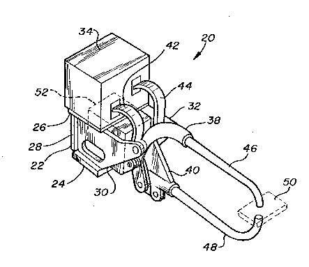
Referring now to the drawings and more particularly to Figure 1, there is
illustrated in perspective an apparatus of the present invention in the form of
an electrical spot welder. The tool shown in Figure 1 is adapted particularly for
attachment to the arm of an industrial robot that would find use in industry
such as automobile assembly lines.
With reference to Figure 1, the overall apparatus is represented by the
numeral 20. A box-like cradle or frame support structure 22 is assembled by
welding or in the alternate with bolts. The support structure 22 has a bottom
plate 24 and a top plate 26 that are positioned in generally parallel relationship
to one another. A back plate 28 is positioned between the top plate 26 and
the bottom plate 24. Spaced apart side plates 30 and 32 are attached to the
bottom plate 24 and the back plate 28. An electrical transformer 34 is
attached to the top plate 26 by a
8 '`A20341 04
plurality of bolts 36, as best seen in Figure 3. The electrical transformer 34
can, by way of example, be a 32 KVA transformer that operates on a single
phase 440 volt, 50-60 hertz input which is coupled to the primary coil of the
transformer 34. The overall apparatus 20 has an upper yoke 38 and a lower
yoke 40 to which a pair of shunts 42 and 44 are, respectively, attached. The
shunts 42 and 44, similar to the upper and lower yokes 38 and 40, are
constructed from a good electrical conductor such as copper. Sine the shunts
42 and 44 are required to undergo repetitive flexing, they are essentially U-
shaped leaf springs each consisting of a plurality of very thin copper sheets.
The shunts 42 and 44 are, of course, attached to the secondary output
terminals of the electrical transformer 34. The upper yoke 38 has attached
thereto an elongate electrode 46, and a similar elongate electrode 48 is
attached to the lower yoke 40. The electrodes 46 and 48 are curved at their
terminal ends so that they can contact opposing faces of a workpiece 50. The
electrodes 46 and 48 are hollow in construction to permit the ingress and
egress of a cooling fluid such as water. The upper and lower yokes 38 and 40
are actuated by a fluid driven cylinder 52 that is positioned within the supportstructure 22. A brief description of the fluid driven cylinder 52 is set forth
immediately below.
Figure 2 is a perspective view of the fluid driven cylinder 52 that
provides mechanical power for the overall apparatus 20. The fluid driven
cylinder 52 has a rear cylinder head 54 and a front cylinder head 56 that are inspaced apart parallel orientation. A bulkhead 58 is positioned between the rear
and front cylinder heads 54 and 56. A rear cylinder body 60 is positioned
between the rear cylinder head 54 and the bulkhead 58. In a similar manner,
and in axial alignment therewith, a front cylinder body 62 is positioned
between the bulkhead 58 and the front cylinder head 56. The front and rear
cylinder heads 56 and 54, the bulkhead 58, and the front and rear cylinder
bodies 62 and 60 are coupled together by a plurality of tie rods 64 that pass
through apertures in the rear cylinder head 54 and the
C~20341 04
bulkhead 58 and are anchored in the front cylinder head 56 by a threaded
engagement. The assembly of the just mentioned parts of the fluid driven
cylinder 52 forms an external housing 65. A reaction piston rod 66 is shown
as it extends outside of the rear cylinder head 56. The reaction piston rod 66
is in axial alignment with the longitudinal axis of the fluid driven cylinder 52.
The reaction piston rod 66 and a front piston rod 68 have longitudinal axes
that are coincident with each other. A double apertured link 70 is attached to
the free end of the front piston rod 68. A clevis 72 with an aperture 74
through the legs thereof is positioned on each side of the front piston rod 68.
The details of the fluid driven cylinder 52 will be explained more fully below.
Figure 3 is a side elevational view that shows the electrical transformer
34 mounted immediately above the fluid driven cylinder 52 to maintain a
compact assembly. The transformer 34 is attached to the top plate 26 by a
plurality of bolts 36. As best seen in Figure 5, the side plates 30 and 32 are of
symmetrical configuration and each contain an elliptical aperture 78 that
permits access to the fluid driven cylinder 52 which is contained within the
support structure 22. The side plates 30 and 32 have cantilevered support
arms 80 and 82 that extend in a forward and upward direction. The support
arms 80 and 82 have bores 84 and 86 that are in axial alignment with each
other. A pivot pin 88 is supported within a pair of flange bearings 90 and 92
which are installed in the bores 84 and 86. The pivot pin 88 and its function
will be discussed in more detail below.
The back plate 28 of the support structure 22 has a pair of spaced apart
brackets 94 and 96 that are positioned on each side of a centrally located
2s aperture 98 in the back plate 28, as shown in Figure 4, and the brackets 94
and 96 are attached to the back plate 28 by a series of bolts 102. The
brackets 94 and 96 each contain a bore 100 which are in axial alignment with
each other into which a pivot block 104 is journaled. The pivot
~ Q2~34 1 04
block 104 provides the sole support for the rear portion of the fluid driven
cylinder 52.
Attention is now directed to the upper yoke 38 which supports the
electrode 46. An upper yoke end 106 contains a clamp arrangement for the
immobilization of the electrode 46. Bolts 108 provide the clamping force
necessary for complete immobilization of the electrode 46. The upper yoke 38
is partially cored for the conveyance of a cooling fluid such as water
therethrough. A fluid ingress port 110 is in communication with the interior of
the electrode 46. A fluid egress port 112 receives the outflow of the cooling
fluid from the electrode 46. The upper yoke 38 is bifurcated into two widely
spread apart legs 114 and 116, as best seen in Figure 5. The apex of the
bifurcation occurs at approximately the broken line 118, as shown in Figure 3.
The upper yoke 38 has a boss 120 that serves as the attachment point for the
shunt 42.
The lower yoke 40 has a clamp arrangement for securing the electrode
48. Bolts 122 generate the clamping force necessary for the containment of
the electrode 48. The lower yoke 40 has a fluid ingress port 124 that is in
communication with the interior of the electrode 48 and the outflow of the
cooling fluid passes through a fluid egress port 126. The lower yoke 40 has an
upwardly extending arm 128 that is clamped to the pivot pin by a bolt 130 and
has a boss 131 to which the shunt 44 is attached. A bore 133 passes through
the upwardly extending arm 128 as shown in Figure 5. The lower yoke 40 has
a downwardly extending clevis 132 adjacent to the electrode 48 which has a
bore 134 through both legs thereof for the accommodation of a pin 136. An
adjustable rod 138 is retained at one end by the pin 136 and at the opposite
end the adjustable rod 138 is retained by a pin 140 that is coupled to the lowerends of spaced apart yoke links 142 and 144. The profile of the yoke link 142
can be seen in Figure 3A. The pin 140 is created by two bosses machined
cylindrically on a cube-shaped yoke through which passes the adjustable rod
138. The cylindrical bosses or pin 140 is journaled in a pair of bores 146
11 CA20341 04
and 148 in the yoke links 142 and 144 and the yoke links 142 and 144 also
have a centrally positioned bore 147 that accommodates a pin 150. The pin
150 also passes through an aperture 76 in the outboard end of the link 70
(shown in Figure 7) which is attached to the front piston 68 of the fluid drivencylinder 52. The yoke links 142 and 144 have a bore 153 positioned at the
top end to contain the pivot pin 88.
Figure 4 is an elevational end view facing the left-hand side of Figure 3.
The shunts 42 and 44 are shown at the top of Figure 3. A shunt adaptor 154
connects the shunt 42 to the electrical transformer 34. In a similar manner, a
shunt adaptor 156 connects the shunt 44 to the electrical transformer 34. The
back plate 28 of the support structure 22 contains the centrally positioned
aperture 98 as well as four additional apertures 158 which permit access to
the tie rods 64 and also provide weight reducing holes in the back plate 28.
An appropriate access aperture (not shown) is also provided in the back plate
to permit access to the fluid port 310. The brackets 94 and 96 are anchored
to the back plate 28 by the bolts 102. The pivot block 104 is journaled in the
bores 100 and, as previously mentioned, provides the sole support for the rear
portion of the fluid driven cylinder 52. The pivot block 104 contains a centrally
located bore 160 that is in axial alignment with the longitudinal axis of the fluid
driven cylinder 52.
Figure 5 is a cross-sectional view taken along line 5-5 of Figure 3 which
shows the pivot pin 88 and the associated components that are journaled
thereon. The pivot pin 88 is supported by the flange bearings 90 and 92
which are seated in the bores 84 and 86 of the side plates 30 and 32. The
downwardly extending legs 114 and 116 of the upper yoke 38 have centrally
positioned intermediate bosses 162 and 164 through which bores 166 and
168 are located. The bores 166 and 168 contain the pivot pin 88. The legs
114 and 116 also have lower extensions 170 and 172 which have end bosses
174 and 176 that accommodate bores 178 and 180. The bores 178 and 180
contain pins 182 and 184 that couple
12 CA2034 1 04
the end bosses 174 and 176 to the pair of clevises 72 that are attached to the
front cylinder head 56 of the fluid driven cylinder 52. The pins 182 and 184
support the front half of the fluid driven cylinder 52.
Figure 6 is a cross-sectional view taken along line 6-6 of Figure 3 that
shows the adjustable rod 138 and its end connections. The pin 140 is shown
within the bores 146 and 148 of the yoke links 142 and 144. The bore 134
through both legs of the clevis 132 contains the pin 136.
Figure 7 is a cross-sectional side view of the fluid driven cylinder 52
taken axially through the cylinder which is shown in perspective in Figure 2.
The fluid driven cylinder 52 has the centrally positioned bulkhead 58 as well asthe front and rear cylinder heads 56 and 54 that are held in spaced relationshipby the front and rear cylinder bodies 62 and 60. The rear cylinder head 54 has
a cylinder head bearing 186 that is positioned in an axially aligned bore 188
and held in position by a retaining ring 190. The reaction piston rod 66 is
threaded at its end 192 for engagement with the pivot block 104, as shown in
Figure 3. The reaction piston rod 66 has a reduced diameter section 194 that
contains a reaction piston 196 flanked by washers 198 and 200. A sleeve
202 is placed over the reduced diameter section 194 in abutment with the
washer 200. A piston stop 204 is placed in abutment against the ends of the
reaction piston rod 66 and the sleeve 202. The reaction piston rod 66, the
washers 198 and 200, the sleeve 202, and the piston stop 204 are locked
together as a unit by the installation of a bolt 206 in a threaded bore 208 in
the end of the reaction piston rod 66. The reaction piston rod 66 has an
axially aligned bore 210 that commences at the threaded end 192 and ends at
radially aligned bores 212 and 214. The sleeve 202 contains notches (not
shown) at its end adjacent to the washer 200 so as not to impede access to
the ends of the radially aligned bores 212 and 214. A floating piston 216 that
contains an axially aligned bore 218 is positioned over the sleeve 202 so that it
is in sliding engagement therewith. The
CA2034 1 04
13
floating piston 216 has an impact plate 220 attached to one face by a plurality
of bolts 222.
The front piston rod 68 consists of a rear piston rod section 224 and a
forward piston rod section 226. The rear piston rod section 224 has a partially
threaded reduced diameter section 228 and an intermediate diameter section
230. A shoulder 232 is formed at the junction of the reduced and intermediate
diameter sections 228 and 230. A rear piston 234 is positioned on the
reduced diameter sections 228 in abutting contact with the shoulder 232. A
threaded nut 236 is engaged with the reduced diameter section 228 to lock
0 the rear piston firmly into engagement with the shoulder 232. The
intermediate diameter section 230 is trained through a bore 238 in the
bulkhead 58. The front end, or right end as viewed in Figure 7, of the rear
piston rod section 224 terminates with a flange 240 of greater diameter than
the intermediate diameter section 230. The rear piston rod section 224
contains a large axially aligned bore 242 that permits the piston stop 204 of
the reaction piston rod 66 to move freely therein. Two radially aligned bores
244 and 246 are positioned in the intermediate diameter section 230 so that
they intersect the axially aligned bore 242.
The forward piston rod section 226 is in the form of a sleeve with an
external diameter 248. The forward piston rod section 226 has an internal
bore 250 that terminates at its forward end with a shoulder 252 that is
adjacent to a smaller diameter bore 254. A link adaptor 256 is contained
within the internal bore 250 with its forward end abutting the shoulder 252.
The flange 240 of the rear piston rod section 224 fits into the internal bore
250 of the forward piston rod section 226 so that it is in contact with the linkadaptor 256. A forward piston 258 is positioned on the intermediate diameter
section 230 of the rear piston rod section 224 adjacent to and in contact with
the flange 240. The forward piston 258 is also in abutting relationship with an
end 260 of the forward piston rod section 226. A series of bolts 262 are
utilized to attach the forward piston 258 to the end
~A20341 04
14
260 of the forward piston rod section 226. The installation of the bolts 262
firmly lock together the rear piston rod section 224, the forward piston rod
section 226, the forward piston 258, and the link adaptor 256.
The front cylinder head 56 consists of two parts, a retainer 264 and a
piston rod bushing 266. The retainer 264 contains as an integral part thereof
the two clevises 72 shown in Figure 2. A vent 268 is threaded into a bore
270 that passes through the wall of the retainer 264. The retainer 264 also
has an internal bore 272 that is in axial alignment with the overall apparatus
20. A slightly larger diameter bore 274 is positioned adjacent to the bore 272
lo and a radially disposed wall 276 interconnects the bores 272 and 274. The
piston rod bushing 266 has an internal bore 278 through which the forward
piston rod section 226 passes and also has a radially extending flange 280 that
fits into abutment against the radially disposed wall 276 of the retainer 264. Aplurality of circumferentially spaced apart bolts 282 clamp the retainer 264 andthe piston rod bushing 266 together.
Returning once again to the bulkhead 58, a partially threaded bore 284 is
positioned in the exterior wall of the bulkhead 58. An intercepting bore 286
connects the bore 284 with a chamber 288. Another partially threaded bore
290 is positioned in the exterior wall of the bulkhead 58. An intercepting bore
292 connects the threaded bore 290 with a chamber 294 which is positioned
between the forward face of the bulkhead 58 and the rear surface of the
forward piston 258. The chamber 294 is in communication with a chamber
296 located in the intermediate diameter section 230 of the rear piston rod
section 224 via the radially aligned bores 244 and 246. The bulkhead 58
contains a recess 298 to accommodate a boss 300 on the rear piston 234.
This arrangement permits the rear piston 234 to move into close engagement
with a rear wall 302 of the bulkhead 58. A forward wall 304 of the forward
piston 258 and the front cylinder head 56 define a chamber 308.
. ~2034 1 04
The rear cylinder head 54 contains a threaded bore 310 in the exterior
wall thereof. The threaded bore is in communication with a chamber 312
which is positioned between the forward wall of the rear cylinder head 54 and
the rear face of the reaction piston 196. The bore 210 and the radially aligned
bores 212 and 214 are in communication with a chamber 314 that is
positioned between the forward face of the reaction piston 196 and the rear
face of the floating piston 216. An additional chamber 316 is positioned
between the forward face of the floating piston 216 and the rear face of the
rear piston 234. The chamber 316 is in direct communication with the
chamber 296.
Figure 8 is a top plan view of the fluid driven cylinder 52 which shows
the tie rods 64 in a clamped position. The tie rod 64 has a wrenching head
318 adjacent the rear surface of the rear cylinder head 54. The opposite end
of the tie rod 64 has a threaded end 320 that mates with a threaded bore 322
in the front cylinder head 56.
Figure 9 is an elevational view of the right-hand end of the fluid driven
cylinder 52 shown in Figures 2, 7, and 8. Corners 324 of the rear cylinder
head, the bulkhead 58, and the front cylinder head 56 are chamfered to reduce
the weight of the overall fluid driven cylinder assembly. The link 70 is shown
in the center of the forward piston rod section 226. A pin 326 is contained in
the link adaptor 256, and best seen in Figure 7.
Figure 10 is a cross-sectioned view taken along the line 10-10 of Figure
7 which shows the forward piston rod section 226 and the link adaptor 256.
The pin 326 is contained in a bore 328 and the pin 326 has an axially
extending bore 330 that contains insulating end caps 332.
Throughout the discussion and description of the invention presented
above, it is assumed that those skilled in the art are aware that certain
insulative materials have to be utilized between some adjacent components in
order to assure the integrity of the electrical system. Also, seals such as 0-
rings have been shown but not individually identified.
CA2034 1 04
16
ASSEMBLY AND OPERATION
The assembly of the present invention is very straightforward. The
cylinder head bearing 186 is installed in the rear cylinder head 54. The
reaction piston rod 66 is pushed through the cylinder head bearing 186. The
reaction piston 196, the washers 198 and 200, the floating piston 216 with its
impact plate 220, and the sleeve 202 are then placed in proper position on the
reaction piston rod 66. The piston stop 204 is placed on the bolt 206 which is
then threaded into the threaded bore 208 in the end of the reaction piston rod
66. The rear cylinder body 60 is then positioned over the reaction piston 196
and the floating piston 216. The above subassembly is then set aside.
A separate subassembly is made of the link 70, the pin 326, the adapter
256, the front piston rod 68, the rear piston rod section 224 and the forward
piston 258. This may be accomplished by aligning the link 70 with the bore
328 in the link adapter 256 and inserting the pin 326 to firmly attach the link
70 to the link adapter 256. The link adapter 256 with the link and pin installedis then inserted in the bore 250 of the front piston rod 68. The flange 240 of
the rear piston rod section 224 is placed onto abutting relationship with the
end of the link adapter 256. The forward piston 258 is then pushed onto the
intermediate diameter portion of the rear piston rod section 224 until it abuts
the forward piston rod section 226 of the front piston rod 68 and then bolted
in placed using the bolts 262. This separate subassembly is then mounted to
the bulkhead 58 and the rear piston 234 by pushing the rear piston rod section
224 through the bulkhead 58 and thereafter mounting the forward piston 258
on the reduced diameter section 228 of the rear piston rod section and
securing the rear piston thereto by way of the nut 236.
The previously set aside rear portion subassembly is then moved into
axial alignment so that the front end of the reaction piston rad 66 enters the
axially aligned bore 242 in the rear piston rod section 224. The tie rods 64 arethen installed to the fluid driven cylinder 52 together as a working unit.
CA20341 04
17
The assembled fluid driven cylinder 52 is positioned within the support
structure 22. The pivot block 104 is installed on the threaded end 192 of the
reaction piston rod 66. The brackets 94 and 96 are positioned on the ends of
the pivot block 104 and then bolted to the back plate 28 with the bolts 102.
5 The electrical transformer 34 is installed on the top plate 26 of the support
structure 22 by the bolts 36. The pivot pin 88 is trained through the bores 84
and 86 of the support arms 80 and 82, the bores 166 and 168 in the upper
yoke 38, the bores 153 in the yoke links 142 and 144, and the bore 133 in the
upwardly extending arm 128 of the lower yoke 40. The lower yoke 40 is then
clamped to the pivot pin 88 by the bolt 130. The pin 150 is then inserted
through the bores 147 in the yoke links 142 and 144 and through the bore
152 in the link 70. The pins 182 and 184 are then inserted through the
clevises 72 and the bores 178 and 180 of the upper yoke 38. The adjustable
rod 138 is attached to both lower ends of the yoke links 142 and 144 with the
pin 140. The other end of the adjustable rod 138 is then coupled to the clevis
132 on the lower yoke 40 with the pin 136. The shunt adaptors 154 and 156
are then attached to the electrical transformer 34. The shunts 42 and 44 are
coupled between the shunt adaptors 154 and 156 and the respective shunts
42 and 44. The electrodes 46 and 48 are inserted into the upper and lower
20 yokes 38 and 40. Fluid connections for cooling and operation, including
additional electrical connections, may then be completed. After assembly, the
fluid driven cylinder 52 is in an operating attitude, that is, it is completely
suspended within the confinement of the support structure 22 but not in
contact with it. The fluid driven cylinder 52 is pivotally supported at the rear25 entirely by the pivot block 104 and in the front the entire support is provided
by the coupling to the upper yoke 38. Thus, the external housing 65 of the
fluid driven cylinder 52 can translate and rotate relative to the surrounding
support structure 22. Also, the external housing 65 can move relative to the
reaction piston rod 66 and the front piston rod 68.
CA~0341 04
18
The present invention will work equally well with a scissor or bell crank
system which has been described above, or with a linear system which will
now be set forth during an explanation of the operation sequences of the
embodiments of the invention.
Figure 11 is a schematic side view of a single stroke clamping and
equalizing cylinder with attached electrodes 46 and 48 in an open position with
respect to a workpiece 50. Fluid pressure is applied to the chamber 312
causing the external housing 65 to move to the left, as viewed in Figure 11,
since the reaction piston rod 66 is held in fixed position. As the external
housing 65 moves to the left, the electrode 46 approaches the workpiece 50.
Fluid pressure is then introduced to the chamber 316, acting on the rear piston
234 which causes it to move to the right. As the rear piston 234 moves to the
right, the front piston rod 68 advances the electrode 48 towards the workpiece
50 to clamp the workpiece.
Figure 12 is a schematic side view which shows the electrodes 46 and
48 in a closed position with respect to the workpiece 50. Since the effective
working area of the reaction piston 196, as it faces the chamber 312, is less
than the area of the rear piston 234 area facing the chamber 316, the
respective fluid pressures may have to be balanced so that undue force is not
applied to the workpiece by either of the electrodes 46 or 48. After the weld
sequence has been performed, the fluid pressure is released in the chambers
312 and 316 and fluid pressure is applied to the chamber 288. The pressure
reaction against the face of the rear piston 234 causes the front piston rod 68
to move away from the workpiece 50. When the rear piston has moved its
maximum distance to the left, the external housing 65 will move to the right,
moving the electrode 48 away from the workpiece 50. The chamber 288 is
vented as the robot is moved to its next work position to begin the next weld
sequence and the weld cycle is ready to start again.
19 CA20341 04
Figure 13 is a schematic side view of a second embodiment of the
present invention which sets forth a double stroke clamping and equalizing
cylinder which provides electrodes 46 and 48 in an open position with respect
to the workpiece 50 as well as a midpoint position. In this embodiment of the
5 invention, the floating piston 216 has been installed on the forward section of
the reaction piston rod 66. During the initial start position, the electrodes 46and 48 are at their maximum distance from the workpiece 50. Also, in the
start position, as shown, the external housing 65 is advanced its maximum
toward the right, as viewed in Figure 13. The floating piston 216 and the rear
piston 234 are in close proximity to the reaction piston 196.
Figure 14 is a schematic side view similar to that shown in Figure 13
except that the electrode 48 has moved to an intermediate position toward the
workpiece 50. Fluid pressure is applied to the chamber 314, moving the
floating piston 216 into abutting relationship with the rear piston 234. The
floating piston 216 and the rear piston 234 move in unison toward the right
until the floating piston 216 reaches its stop position against the piston stop
204. The advancement of the rear piston 234 to the right carries the electrode
48 to an intermediate position with respect to the workpiece 50.
Figure 15 is a schematic side view that shows the electrodes 46 and 48
20 in contact with the workpiece 50. To arrive at this position from the
intermediate position set forth above, the fluid pressure in the chamber 288 is
exhausted and maintained in the chamber 314. Fluid pressure is then applied
to the chambers 312 and 316. The rear piston 234 moves to the right causing
the electrode 48 to contact the workpiece 50. At the same time the external
25 housing 65 moves to the left bringing the electrode into contact with the
workpiece 50. After the weld has been performed on the workpiece 50, the
electrodes 46 and 48 can be returned to the intermediate position by releasing
the fluid pressure in the chambers 312 and 316, and by applying fluid pressure
to the chamber 288 which causes the rear piston 234 to
CA2034 1 04
move to the left and the external housing 65 to move to the right. The
electrodes 46 and 48 can be moved to the fully opened, or start position, by
venting the fluid pressure from the chamber 314.
Figure 16 is a schematic side view of a third embodiment of the present
5 invention which shows a multiple piston high force generating system with the
electrodes 46 and 48 in the open position with respect to the workpiece 50.
In this concept of the invention, the bulkhead 58 is attached to the external
housing 65 to the right of the rear piston 234. The forward piston 258 is
attached to the front piston rod 68 between the bulkhead 58 and the right end
10 of the external housing 65. The initial start position is shown in Figure 16 with
the reaction piston 196, the floating piston 216, and the rear piston 234 all tothe left in close proximity to the left end of the external housing 65.
Figure 17 is a schematic side view similar to that shown in Figure 16
except that the electrode 48 has moved to an intermediate position with
respect to the workpiece 50. The electrode 48 arrives at its intermediate
position by introducing fluid pressure to the chamber 314 causing the floating
piston 216 to move to the right, carrying the rear piston 234 to the right. The
pressure in chamber 314 is maintained at this time.
Figure 18 is a schematic side view that shows the electrodes 46 and 48
20 in contact with the workpiece 50. Fluid pressure is then applied to the
chambers 312 and 316 as well as the chamber 294. The chambers 316 and
294 can be pressurized from a common source. The force exerted by the
electrodes 46 and 48 is increased considerably because the increase in area
provided by the combination of the rear piston 234 and the forward piston 258
25 acting in unison. During the advancement of the forward piston 258 toward
the right the chamber 308 is vented to the atmosphere. The electrodes 46 and
48 are returned to an intermediate or midpoint position by removing the
pressure from the chambers 312, 316 and 294 and applying pressure to the
chamber 288. The
21 CA2034 1 04
electrodes 46 and 48 are then returned to a full open position by removing the
pressure from the chamber 314 and maintaining pressure to the chamber 288.
The pressurizing and venting of the chambers heretofore discussed in
describing the operation of the various embodiments of the invention can be
5 accomplished by the utilization of two-way and three-way valves as is readily
apparent to those skilled in the art. Additionally, the term fluid pressure has
been referred to throughout the discussion. Such terminology applies equally
well to liquids such as oil and to gaseous mediums such as air.
While the illustrative embodiment of the invention has been described in
10 considerable detail for the purpose of setting forth practical operative
structures whereby the invention may be practiced, it is to be understood that
the particular apparatus described is intended to be illustrative only, and thatthe various novel characteristics of the invention may be incorporated in other
structural forms without departing from the spirit and scope of the invention
15 defined in the appended claims.
What is claimed is: