Note: Descriptions are shown in the official language in which they were submitted.
COEL.~ATION APPA~ATUS
FOR X-~AY sEAM CORREC~IOU 15CT03280
Z~ 32~
This invention relates to x-~ay collimatorg for use in
computed tomography systems and the like and specificalt~ to
a collimation system for correct.ng er~ors in the x-ray fan
beam location and angle of incidence with the detector
mechanism resulting from misalignment of the position of the
x-ray tube focal spot.
Computed tomography systems, as are known in the art,
typically include an x-ray source collimated to form a fan
beam directed through an object to be imaged and received by
an x-ray detector array. The x-ray source and detector array
are orlentated to lie within the x-y plane of a Cartesian
coordinate system, termed the "lmaging plane". The x-ray
source and detector array may be rotated together on a gantry
within the imaging plane, around the image object, and hence
around the z-axis of the Cartesian coordinate system.
Rotation o~ the gantry change~ the angle at whlch the fan
beam intersects the imaged ob~ect, termed the "gantry" angle.
The detector array is comprised of detector elements
each of which measure~ the inten~ity of transmitted radiation
along a ray path projected ~rom th~ x-ray sourcQ to that
partlcular detector element. At each gantry anqle a
pro~ection i3 acquired comprlsed of intensity signals from
each of the detector elements. The gantry i5 then rotated to
a new gantry angle and the procesQ i~ repeated to collect an
number of pro~ectlon~ along a number of gantry angle~ to form
a tomographlc pro~ection set.
Each acquired tomographic projection set may be s~ored
in numerical form for later computer processing to
reconstruct a cross sectlonal imaqe accord~ng to aLgorithms
known in the art. The reconstructed image may be displayed
on a conventional CR~ tube or may be converted to a film
record by means of ~ computer controlled camera.
2g
-2- 15CT03280
The x-ray source is ordinar7ly an x-ray ~tube" comprised
of an ev~cuated glaoc x-ray envelope containing an anode and
a cathode. X-rays are produced when electronc from the
cathode are accelerated aqainst a focal spot on the anode by
meana of a high voltage across the anode and cathode. ~he
voltage applied across the anode and cathode, the current
flowing between the anode and cathode, and the duration of
the expo~ure, for a given x-ray procedure, is termed the
"exposure technique n .
The efficiency or energy converqion in ~enerating x-rays
is low, and aa a consequence, con3iderable heat is developed
in the ancde of the x-ray tube. ~or this reason, the anode
may be rotated at high speeds so that the focal spot
con-qtantly strikes a new and cooler area of the anode. ~ven
lS so, the surface temperature of the anode may riqe as high as
2000 C during the acquiqition of the projections for a
serie~ of tomo~raphlc pro~ection set~ and the anode
aupporting structure including the shaft on wh~ch it rotateq
may ri~e to 400C or more.
A3 the x-ray source heat~ up, thermal expansion of the
anode supportlng ~tructure relult~ in movement of the focal
qpot relatlvo to the gla~ envolope of the x-ray tube and
movement of the fan beam. She focal spot may move as much as
0.25 mm ~0.01 inch) due to thermal expan~ion durlng the
ac~uiqlt~on of a ~erle~ of tomographlc projectlon~.
The anode shaft ls aligned with the z-axis, about which
the gantry rotates, to prevent gyroacopic tor~ues from acting
on the rotating anode during movement of the gantry. ~hermal
expanqion of the anode support structure therefore tends to
move the focal RpOt along the z-axiq. Wlth a fixed
collimator po~ltlon, movement of the focal apot in the z-axis
sweep~ the fan beam in the oppoqite dlrectlon along the
surface of the detector array.
2~
~3~ 15CT03280
Another source of motlon oS the focal spot is mechanicaL
stres~ of the gantry and rotating anode as the gantry
rotate~. Thls stress results fsom the changing angle of
gravitational acceleration and the changing magnitude of
S centripetal acceleration as a function of the rotational
veloclty of the gantry, actlng on the gantry and anode.
TheQe resulting forceq contrlbute up to 0.25 mm (0.01 inch)
of addltional focal spot motion.
~he detector array may be an ionization type detector or
solld state detector as are known in the art. Both detector
type~ exhibit changeq in their sen3itl~ity to x-rays as a
functlon of the po-~ition of the fan beam along their surface.
Accordingly, movement of the fan beam as a result of t~.ermal
drift or mechanical deflection of the x^ray source focal spot
may change the strength of the signal from the detector
array. Such change~ in signal strength during the
acqulsition of a tomographic projection set produce ring like
image artifact~ in the re ultant recon~tructed image.
Wlth a fixed collimator position, movement of the
focal spot in the z-axis al o affects the alignment of the
fan ~eam wlth tho imaglng pl~ne. The mathematlc~ of image
reconstrùctlon assumes that each acquired pro~ection is taken
wlthln a slngle plane. Lack of parallelism of the fan beam
with the lmaging plane will also produces shadlng and streak
image arttfact~ ln the reconqtructed image. Also, for small
slice width~, the mi~aLignment due to motion induced stress
on the gantry and anode may Qlgn~ficantly enlarge the
effective slice wldth o~ images reconstructed from opposing
but misaligned views. Thts mot'on induced misallgnment will
reduce contra~t resolution for small imaged ob~ects, such a~
leQlons, making them harder to detect. ~n addltlon, the
spat~al resolutlon o~ the CS im~ging system will be reduced
for high frequency features at oblique angles to the slice.
;~03~3;;~
_4_ 15CT03280
S~lmmar~r af the r~ e~
According to the present invention the collimator
position Cz is automatically adjusted so a~ to control :he
allgnment of the fan beam plane and therefore to reduce imaqe
artifacts. A z-axi~ offset detector, posltioned to ir.tercept
the fan beam, produces a fan beam positi~n signal dependant
. on the position of the fan beam plane and an error signal is
generated from that position signal. A collimator controller
re~ponsive to the error signal, change~ the collimator
po~ition Cz so aq to reduce the error signal.
It is one ob~ect of the invention to reduce image
artifacts re~ulting from the changes in the fan beam position
with respect to the detector. In a first embodiment, t~e
error signal is made proportional the difference between the
fan beam position and an alignment point. The collimator
controller repo~ition~ the collimator to reduce the error
signal thereby aligninq the fan beum plane with the alignment
polnt. Drift of the fan beam plane with re~pect to the
d-toctor array i~ thereby corrected.
It i~ anothe~ ob~ect o~ thc inventlon to reduce imaqe
artifact~ re~ultlng from the devlation of the angle of the
fan beam plane from the angle of the image plane. In a
second embodiment, the error signal is made proportional to
the difference b-tween the po~ition of the fan beam and the
po~itlon of the collimator. The collimator controller
repo~itlont the coll~ator to reduce the error ~ignal by
maklng the colli~ator po~ition equal to the po~ition of fan
beam, which allgn~ the fan beam plane with the lmaging plane.
Deviation of the angle of the fan beum plane from the image
plane. i3 thereby corrected.
~ t i~ another ob~ect of th- invention to permit the
rapid alignment oS the x-ray ~ource with the detector array
during initial a~embly or later replacement of the x-ray
3Z~
-S- 15CT0~280
source.or detector array. The adjustable coll~mator cf t~e
pre~ent invent~on permits the x-ray source to be alisned
approximaeely by mechanicaL stops. Flnal, accurate aligr.ment
i~ performed automatlcally by movement of the colllmator.
It ls yet another object of the invent~on to allo~ ~he
use of solid ~tate detector array elements with higher
variations in sensitivitie~ a3 à function of the posit~on of
the fan beam on their surface (z-axis sen~itivity).
Presently, solid state detector elements are culled to select
units with low z-axiq sensitivity. The present lnvention, by
reduc$ng the z-axis drift of the fan beam, permits the use of
detectos element~ with higher z-axls sen itivitie~, t~.ereby
reducing wa~te and exyense.
During the initial projection acqui~ition~, ~he correct
collimator position is estimated based on the previous use of
the x-ray tube and hence the heat absorbed by the x-ray tube
anode and its supporting structure. A memory store~ the
previou~ expo~urc techniques u~ed with the x-ray tube and the
tlme of uso of each technlque. From thls lnformatlon, the
thermal oxpan~lon o~ the tubo 1~ predlctod and a value of the
current focal spot posltlon Fz estl~ated. The collimator
controller posltlons the colllmator in reJpOnse to the
predlcted Yalue of Fz.
It i~ thut another ob~ect of the invention to allow for
corsectlon of the fan beam plane pr~or to the detesmination
of fan be~m posltion by means of the z-axis offset detector.
In another e~bodiment, mechanlcal ~tres~es acting on the
gantry and the x-ray tube are estimated based cn the gantry
speed and angle. Fro~ thl~ lnfosmatlon, the mechanical
deflection of the focal spot lq estlmated and a value of the
current focal ~pot po~ition Fz computed. The collimator
controller po~ltlon~ the collimator ln response to the
predlcted value of Ez.
203~329
-6- 15CT03280
It l~ thu~ another ob~ect of the invention to allow for
correction o~ the fan beam planc re~ulting from motion
induced mechanical stre~se~
Other ob~ect~ and advantage~ be~ide~ tho~e discussed
S above shall ~e apparent, to tho~- experlcnced l~ the art,
from th- deJcrlpt~on of a preferred embodlment of the
lnventlon whlch ~ollow~ ~n the de~crlptton, reference is
made to the accompanylng drawing~, whlch form a part hereof,
and whlch ~llu~trate one example of the 'nventlon Such
example, however, ~ not exhau~ttvc of the varlou~
alternative form~ of the inventlon, and therefore reference
~ made to the clalm~ which follow the de~criptlon for
determlnlng the scope of the ~nventlon
r~e~ ne~L~t pt t ~n ~1' t~e DraY~ r~
Flgur- 1 1J a ~ch-matlc r-pre~entatlon of an x-ray
~ource and x-ray d-tector a~ may be w -d with the pre~ent
lnv ntlon;
Figur- 2 1~ a ~ch-matlc vlew of the per'pheral detector
element~ o~ the detcctor array of Flgure l;
Flgure 3 l~ a p-r~p-cttv- vl-w o~ th- colllmator
a~embly of th- pr-~-nt inv ntlons
Flgur- 4 ~a) and (b) ar- cro~ ~ectlonal vlew~ of th-
mandr-l of th- coll~ator of F'gure 3 ~howlng orlentatlon of
the man~r-l for thlck and thln fan beum~ re~pectlvely;
2S Flgur- 5 11 a Jlmpllfi-d cro~ ~ectlonal vtew of th-
path of t~- x-~ay fan beam, tak-n along lln- 5--5 ln F'gur-
1, wlth t~e x-ray tube anod , the coll~mator and the detector
array exaggerated for clarlty;
Flgure 6 i5 a cro~ ~cctlonal vicw, ~lmllar to that of
Flgure 5, ~howlng th- ;ffect of thermal drlft of the x-ray
anode on fan beam allgnment;
-7- 15CT03280
Figure 7 i3 a cross sectional view, similar to that of
Fi~ure 6, showin~ rotation of the co~limator to make the fan
beam plane parallel with the imaging plane:
Fi~ure 8 is a cross sectLonal view, similar to that o~
Figure 6, showing rotation of the collimator to align t~.e fan
beam withln the detector lrray;
Figure 9 is a block diagram showing the control system
for the collimator of Figure 3 according to the present
invention.
_----
Referring to ~igure 1, a gantry 20, representative of
a "third generation" computed tomography scanner, incl-des
an x-ray ~ource 10 collimated by collimator 38 to project a
fan beam of x-rays 22 through imaged ob~ect 12 to deteceor
array 14. The x-ray source 10 and detector array 14 rotate
on the gantry 20 as indicated by arrow 28, with~n an
imaging plane 60, aligned with the x-y plane of a Cartesian
coordlnate system, and about the z-axis of that coordinate
qyatem.
Sho detector array 14 ls comprised of a num~er of
detector elements 16, organlzed within the imaging plane
60, which together detect the projected image produced by
the attenuated transmiqsion of x-ray~ through the imaged
o~ect 12.
The fan beam 22 emanates from a focal spot 26 in the
x-ray source 10 and is dlrected alons a fan beam axis 23
centered within the fan beam 22. The fan beam anqle,
mea~ured along the broad face of the fan beam, i~ larger
than the angle subtended by the imaged ob~ect 12 so that
two perlpheral beam 24 of the fan beam 22 are transmitted
pa~t the body without substantlal attenuation. These
~6)3~3~
3 15CT03280
peripheral beams 24 are received by peripheral detector
element~ 13 withln the detector a~ray 14.
Referring to F~ure 3, uncolllmated x-rays 19
radlating from the focal spot 26 in the x-ray source lO
~not shown in F~gure 3) are formed into a coarse fan ~ie~m
21 by primary aperture 40. $he coarse fan beam 21 is
collimated lnto fan beam 22 by means of collimator 38.
Refersing generally to Flgures 3, 4ta~ and 4(b),
collimator 38 ~s comprlsed of a cylindrical x-ray absorbing
molybdenum mandrel 39 held withLn the coarse fan beam 21 on
bearlngs 42 allowing the mandrel 39 to rotate along itS
axisi. A plural1ty of tapered slots 41 are cut through the
mandrel's diameter and extend along the length of the
mandrel 39. The slots 41 are cut at ~arying angles about
the mandrel's axis to permit rotatlon of the mandrel 39 to
brinq one such slot 41 into alignment with the coarse fan
beam 21 so as to permit the pas~a~e of some ray~ of the
coarse fan beam 21 through the i~lot 41 to form fan beam 22.
Referring to Fiyure 4~a) and 4~b), the tapered slots
41 are of varylng wldth and hence the rotatlon of the
mandrel 39 allow~ the width of the fan beam 22 to be ~aried
between a narrow ~1 mm) a~ ~hown ln ~lqure 4(b) and wide
(lOmm) as shown ln Figure 4(b). The ~lotsi 41 ensure
dimenslonal accuracy and repeatabllity of the fan beam 22.
$he slot~ 41 are tapered so that the entrance
aperture 43 of each ~lot 41, when or~entated with re~pect
to the coarse fan be~m 21, ii3 wlder thAn the exit aperture
45. The exlt aperture 45 deflnes the width of the fan beam
22 and the extra width of the entrance aperture 43 preYents
either edge of the entrance aperture 43 from blocklng the
coarse fan beam 21 durlnq rotatlon of the mandrel 39 when
~uch rotatlon ls uqed to control the allgnment of the fan
beam axis 23 as will be discused ln detall below.
~()3~3~
~9~ 15CT03280
Reerring again to ~lgure 3, a positioning motor 48
is connected to one end of the mandrel 39 by flexible
coupliaq S0. ~he ot~er end of the mandrel 39 Ls attached
to a position encoder 46 which allows accurate position
of the mandrel by motor 48. ~an beam angle shutters 44 at
either ends of the ma~drel 39 control the fan beam angle.
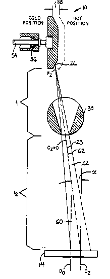
Referring to ~igure S, the x-ray qource 10 is
comprised of a rotating anode 52 held with~n an evacuated
glas~ tube (not shown) and supported by supportlng
structure including principally anode shaft 54 which is
heLd on bearlng3 56 ~one shown), The coarse fan beam 21
e~anate~ from focal spot 26 at the surface of the anode 52.
The positlon of the focal spot 26 along the z-axi~ will be
termed Fz and will be defined aa being equal to zero when
the focal spot 26 is at a reference polnt Fo defined
further below.
The coar-Qe fan beam 21 is then colllmated by the
colllmator 38 to form a fan beam 22 as previou~ly
de~crlbed. The z-axl~ positlon of the center o~ the exit
aperture 45, for the ~lot 41 that i~ allgnod with the
coar~e ftn beam 21 (shown ln Flgure 3) will be termed Cz
and will be deflned a~ being equal to zero when the center
of the exit aperture 45 13 at a reference line Co whlch
will al~o be deflned below.
2S Referrlng to Flgure 2, the fan beam 22 (not shown in
Flgure 2) expo~e~ an area 36 on the facè of the detector
array 14 and accordlngly on the face of the peripheral
detector element~ 18. Peripheral detector elements 18
include reference detector~ 34 and a z-axi~ offset detector
30 30. The face of z-axls off~et detector 30 19 partlally
occluded by a wedge filter 32 whlch i~ tapered to bloc~ a
changing percentage of the fan beam 22 a~ a functlon of the
fan beam positlon with re~pect to the z-axl~ off~et
detector 30. The z-axl~ po~ltlon of the center of exposure
~3~3;~9
-10- 15CT08280
area 36 with re3pect to the detector array 14 will be
termed t~e fan beam position, Dz ant is deflned as equal to
zero when D2 is e~ual to a ~eferenoe value Do Aa wiil be
defined below. A detailed descr~ptlon of the detection of
fan beam positlon, through the use of a wedge filter 32 in
con~unctlon with a z-axis of~set detector 30 and reference
detector 32 ls de cribed in ~.S. patent 4,5S9,639,
entitled: "X-ray Detector with Compensation for Heighe-
Dependant Sensitivity and Me~hod of Using Same", issued on
December 17, 1985, a~signed to the same as~ignee as the
present invention, and hereby incorporated by reference.
Fo, Co, and Do are defined such that the fan beam axis
23 is parallel to the imaging plane when the focal SpOt is
at Fo and the collimator is at Co and the fan beam is
centered at Do on the detector array 14.
Referring again to Figure 5, the plane containing ~he
centerllne of the focal spot 26, the center line of the
exit aperture 45, and the centerline of the exposure area
36, and thu~ bi~ecting the fan beam 22 in the z axi~
direction, wtll be termed the "fan beam plane" 62.
As pr¢viou~ly d-~cribed, tho focal ~pot 26 may not be
aligned with the imaging plane 60 either because of thermal
drift of the anode 52 and its ~upporting structure or
because of minor misalignment of the x-ray source 10 during
a~embly. Re~erring to ~igure 6, the anode 52 is shown
dl~placed from.the lmaging plane 60 by miqalignment
dl~tance 58. T~e effect of this misalignment i~ to
di~placo focal spot position Fz away from the imaging plane
60 and to move the the center of the fan beam exposure area
36 in the oppo~ite direction accord~ng to the formula:
DZ--F2 11 ( 1 )
1329
~ 15CT03280
where ll is the distance between the focal SpOt 26 and
the center of the exlt aperture 45 and 12 i the distance
between the center o~ the exit aperture 45 and the detector
array l4. ~or a typlcal computed tomography sy~tem the
ratio l2 i3 approximately 3.3.
Aq a re ult of the movement of the focal spot 26 as
shown in ~lgure 6, the exposure area 36 is no lonqer
centered at Do and the fan beam plane 62 i~ no longer
parallel with the imaging axis 60 but deviate~ by angle a.
Referring to FLgure 7 the collimator 33 may be
rotated to positlon Cz removed f~om the lmaging plane 60.
When Cz is equal to Fz, then Dz will also equal C2 and the
fan beam plane 62 will be reqtored to being parallel with
the imaging plane 60. Thls correction of the angle of the
fan beam plane 62 will be termed "parallelism correction .
Alternatively referring to Figure ~ the collimator
33 may be rotated so that Cz i-~ equal to Fz l +2l2. Dz will
thus be made e~ual to Do and the exposure area 36 will
agaln bo contered at Do. Corroctlon of the positlon of the
Or the fan beam expo~ure area 36 with respect to the
detector 14 wlll be termed "z-ax~3 offset correction .
In summary, rotation of the coll~mator 3~ may correct
for mi~alLgnment of the fan beam plane 62 either to make it
parallel wlth the imaging plane 60 or to bring the exposure
area 36 into allsnment with Do on the detector array 14.
A~ previously di~cussed both of these correctlons will
reduce imaqe artlfacts.
It will be understood by one skilled in the art that
first a parallelism correction may be performed to make the
~0 fan beam plane 62 parallel to the imaging plane 60. The
re~ulting Dz value may then be defined a~ Do and maintained
again~t thermal drift of the focal spot 26, to ensure
;~33~32~
-12- 15CT03280
constant detector 14 gain by means of continulng z-axis
offset correctlon.
Referr-ng ~o F~gure 9, a feedback control system
controls ~he po~ition Cz of the oollimator 38 in response
S to change~ in the focal spot 26 posltion Fz for either
parallellsm correction of z-axis offset correction. ~he
indlvidual elements of the control sy~tem may be
implemented by a combination of dlscrete digitaL and analog
functional module~, a are known in the art, or, in the
preferred embodiment, by means of a high speed diqital
computer 71 ~not shown) interfaccd eo analog circuit
module~ by analog-to-dlgital and digitally controlled
interface circuits to be de~cribed. The functional blocks
implemented by computer 71 will be indicated in the
following di cu~lon by the prefix "30ftware-n and are
enclosed in da~hed line 71 ln Figure 9.
Slgnals from the z-axis off~et detector 30 and the
reference detector 34 are received by an z-axis offset
detector data acqui~itlon ~y~tem ~DAS~) 68 and a reference
detector DAS 70 for ampli~lcation and digitization. The
di~ltlzed ~lgnal~ are communlcatod to computer 71.
Sho ~lgnnl from the z-axi~ detector 30, i9 tlvided by
the signal fro~ the refercnce detector 34 at software-
dlvldcr 72, implemented by computer ~1 as ha~ previou31y
been de~crlbed, to produce a ~an beam poRition signal
indicatlng the z-axla po~ition Dz of the exposure area 36
on the detector array 14. Dlvision of these two signals
reduce~ the effect of varlation~ in the intensity of fan
beam 22 unrelated to the actlon of the we~ge filter 32.
The mea~ured value of Dz produced by the signal.~ from
detector array 14 i~ labeled Dz~ to dlstlnguish lt from the
predicted value Dzp produced from a ~oftware
thermodynamic/geometrlc model and a ~oftware mechanical
.~tre~ model 81 a~ will now be de3cribed.
~3~1 ~32~
15CT03280
-13-
The previous exposure techniques employed with the x-
ray source 10, i.e. x-ray tube volta~e, x-ray t~be current,
and exposure duratlon, are rece~ved f~om the x-ray source
controller (not shown) and stored ln computer memory 78
along with the tlme at whlch the exposure wa-~ init~ated, ~o
created a record of the total energy input to the x-ray
source 10. A software thermodynamlc/geometric model 76
equates the total energy input to the x-ray source 10 as a
functlon of time to the temperature of the various x-ray
tube components and thereby predicts the thermal expansion
of these tube components and the corre~ponding movement of
the focal spot 26 as a function of tlme. Thl~ software
thermodynamic/geometric model 76 may be constructed
emplrically throuqh observation of a tube of a glven
deqign, and recording of the focal spot movements as a
function of temperature, tlme and uQe. In it~ simplest
~mplementation the software thermodynamic model 76
incorporates a look-up table holding the~e mea~ured values.
~he techni~ue hi~tory stored ln memory 78 19 used by
the thermodyna~ictgeometric model 76 to produce the
predlcted value of the focal spot positlon due to thermal
expan~lon.
Slmilarly, th- Qoftware mechanical streQQ model 81 is
a table of emplrically determined or analytically computed
focal 9pot movement value~ aa a function of gantry rotation
speed and gantry tllt angle. Tho gantry angle and speed is
received by the software mechanical Ytre~s model 81 from
angular encoder~ attached to the gantry ~not shown) as is
under~tood in ~he art.
The focal spot movement predicted by the 30ftware
thermodynamic model 76 is added to the movement prPdicted
by the -~oftware mechanlcal stregs model 81 by software
adder 82 to provide predicted focal spot po~ltion Fzp. A
~3~3~9
-14- 15CT03280
predicted value of D~, termed Dzp, is then calculated by
software scaler 83 as followY:
Dzp--~Fzp-~C)~ C (2)
where ~C-CZ-Co
S Referring again to ~igure 9, the negative input of a
second software-adder 74 maybe connected either to Dzm~
when the x-ray source 10 is on and Dzm may be measured, or
to Dzp when the x-ray source 10 is off.
One of two error signals El or e2 ia thus produced by
the software-adder 74 depending on the type of correction
de~ired. For parallelism correctlon, 1 ls produced by
subtracting Dz from Cz:
El-Cz~D2
A feedback loop controlling the collimator position
and descrlbed below will act to reduce this error term El
thcreby making Cz-Ds~ thc condition required for the fan
beam plane 62 to be parallel to the imaglng plane 60.
For z-axla o~set correctlon, e2 ia produced by
~ubtractlng Dz from Do:
C2-Do-Dz (4)
Agaln the feedoack loop controlling the collimator
poaltlon will act to reduce this error term e2 thereby
making Dz-Do, the conditlon required for the fan beam
exposure area 36 to be allgned wlth Do.
Error term Cl or 2 is integrated aa a function of
tlme a~ indicated by software-integrator 75-to produce a
collimator poaltlon change ~lgnal ~C whlch is 3ummed by
means of software-adder 77 to Co to produce Cz, the
collimator poaitlon. The collimator po~ltlon Cz ia
-15- ~G)31~3~9
15CT03280
connected to a motor ccntroller 80 to posi~ion the
colllm~tor 38
Motor controller 80 is implemeneed as an analog
module d~stlnct from the computer 71 and controlled by a
S dlgital signal from the computer 71 The motor controller
80 first convert~ the Carteqian poaitlon C~ to the
correspondin~ polar or rotational coordlnateq of the
colllmator actuator and poqitions the collimator 38 to
position Cz by means of feedbac~ loop includ~nq motor 4~
and po~ition encoder 96 Motor controller 80 also includes
a mean~ for offsettin~ the collimator 38 to the various
angular offqet-Q required to bring various of the slots 41
into alignment with the fan beam 21
During the acquisition of the firqt projections or
lS after the tube has cooled for a period of time, the error
signal ~1 or e2 is derived from the thermodynamic/geometric
model 76, the mechanical stres~ model 81, and the fan beam
po~ltlon signal Dzm from ~oftware-divlder 72 Thls
procedure is adoptcd to prevent large amplltude collimator
po~ltlon Cs correctlon~ durlng the stablllzatlon of Dz~
upon inltlal expo~ure o~ the z-axi~ off~et detector 30 and
reference channel 32
Arter the Dza ha~ stabilized, lt i~ reconnected to the
software-addor 74 and also serve~ to correct the predlcted
value o~ the fan beum po~ltlon Dzp The value of Dzm is
also u~ed to correct the value of Fzp derived by the
thermodynamlc ~odel 76 per the following equatlon
Fzp-~C + ~C-Dz~ 5)
where ~C'C2-Co
The above de~crlptlon ha~ been that of a preferred
embodlment of the present lnventlon ~t wlll occur to those
who practlce the art that many modlficat~ona may be made
~3~3Z9
-16- 15CT03280
without departlng from the spi~it an~ scope of the inven~ion.
~or example, thc ~an beam may be aligned to a position that
is a compromi~e between reducing z-axls z-axi~ offset an~
reducing pa~allelism error. In order to apprise the public
Or the varlous embodiments that may fall withln the scope of
the invention, the following claims are made.
,
: ,. . .
: !
' . "`