Note: Descriptions are shown in the official language in which they were submitted.
4~44
-
METHOD AND APPARATUS FOR THE DETERMINATION OF
FORMATION FLUID FLOW RATES AND RESERVOIR DELIVERABILITY
BACKGROUND OF THE INVENTION
10 1. Field of the Invention
During the life of a well, periodic measurements and tests are performed to better
understand the quality of a reservoir. Some tests are made at the surface and some are performed
down-hole by sophisticated tools that are lowered into the wellbore.
This invention involves a method and an apparatus for acquiring formation fluid flow rates
and calculating the reservoirs absolute open flow (AOF) potential by means of a wireline conveyed
tool. The field of this invention relates specifically to, designed down-hole tools to measure
formation fluid flow rates and p,es~ules. In the operation of drilling oil and gas wells, it is
desirable to evaluate the reservoir deliverability at a stage early enough to make the best
20 economical decision regarding the disposition of the wellbore. This invention allows for the fluid
flow rates to be determined by providing a method and an apparatus lowered on a wireline into
an uncased or cased borehole. A set of inflatable packers are used to isolate an interval of a
formation from the wellbore fluids prior to a flow rate test being performed. The results obtained
during the flow test period are transmitted to the surface whereby calculations and deductions can
be made as to the validity of the measurements. This ability to record and interpret data as to the
potential flow rate of a reservoir, essentially in real time, is of extreme importance to those
engaged in well completions and reserve determinations.
2.Description of the Prior Art 2~3~444
In the past, representative formation fluid flow rate measurements have been primarily
restricted to operations involving the use of drill pipe type methods (Drillstem Tests) or production
testing. Attempts have been made to measure flow rates using wireline formation sampling and
testing tools for many years. The Formation Tester, as it is well known, is a wireline tool used for
measuring inferred formation properties and collecting fluid samples. A variety of tools are used
to obtain uncont~min~ted formation fluid samples by means of isolating the wellbore, collecting
a sample and measuring the fluid properties. Based on the fluid test results the sample is recovered
in a chamber or rejected to the borehole. In the past, the measuring of formation properties by
wireline tools has produced unreliable information on the reservoirs ability to produce fluids and
40 estimate the fluid flow rates as a result of the limited tool capacity and capabilities. The financial
benefit of performing fluid flow rate tests using a wireline tool, combined with increased data
reliability and accuracy is of immense concern to the oil and gas industry.
The rem~ining discussion on prior art methods and apparatus will strictly be in regards to
downhole wireline tools and operations.
In the past, a pair of packers mounted on a wireline tool were lowered into a borehole to
obtain formation fluid samples. Expanding the packers isolated an interval in the borehole from
which fluids may be drawn into the tool for analysis. If the formation permitted fluid flow and
the fluid was suitable for sampling, collection to a sample chamber was performed. An example
of such a tool is described in U.S. Pat. No. 4,535,843 entitled " Method and Apparatus for
50 Obtaining Selected Samples of Formation Fluids". The tool described in the '843 patent was used
to measure fluid properties and collect samples which complied to predetermined constraints and
was not used to determine fluid flow rates.
Many of the multi purpose wireline formation testers utilize a probe assembly which
extends through a sealing pad into the formation to isolate the tools' sample point from the
wellbore. These tools are capable of obtaining ples~ule measurements and if desired a sample of
the fluids in communication with the sample point. However, during the drilling process of a
~(~3~444
borehole, the drilling fluid will invade a permeable formation causing pressure and fluid
distortions. Therefore, to make accurate measulelllents of the essential parameters, virgin reservoir
conditions must be observed by the tool. A tool capable of removing the drilling effects must be
60 used before meaningful data can be obtained. The probe type tester has been used to estimate
formation permeability, but due to the shallow depth of investigation during fluid removal the tool
has its limitations. Multiple probe modifications have been designed in an attempt to improve the
situation (such as the tool described in U.S. Pat. No. 4,860,580 entitled Formation Testing
Apparatus and Method). The tool in the '580 patent was intended to predict the nature of the
formation connate fluid by the accurate determination of the pressure-depth gradient between
the two probe assemblies. By increasing the distance between the probes, deeper depth of
investigation can be achieved. But, this technique is limited due to the small bore hole wall area
exposed with the probe tools which affects the fluid extraction rate towards the sample point. This
sink point also causes the magnitude of the plesaule response between the two probes to decrease
70 with increased probe spacing. Therefore, to measure unrestricted fluid flow rates it is desirable
to use a device which is not a probe type testing tool.
Other formation sampling and testing devices have been implemented such as the apparatus
found in U.S. Pat. No. 4,513,612 entitled Multiple Flow Rate Formation Testing Device and
Method. The tool described in the '612 patent employs the use of a fluid sampling probe and is
restricted to the same limitations as discussed earlier.
The apparatus of the present invention is designed to allow a large area of the borehole
to be exposed for fluid removal by the use of a set of inflatable packers spaced some distance
apart which isolates an interval of the formation. This will reduce the affect of the point source
used in probe tools and enhance the flow rate determinations. The tool employs a pump which is
80 used to draw fluids to an inlet positioned between the packers and discharges the fluid above the
top packer. Utilizing the pump to control flow rate and allowing the formation to produce larger
volumes of fluids than known designs, permits the opportunity to determine the absolute open flow
(AOF) rates of the formations being tested.
Flow control by using a restriction device to allow sampling at a constant pressure or
2~ 44
constant flow rate can be used to enhance multi probe permeability determinations and such a
sampling tool is illustrated in U.S. Pat. No.4,936,139 entitled Down Hole Method for Determination
of Formation Properties. Since the sampling apparatus in the '139 patent had an objective of
measuring formation permeability and extracting uncont~min~tec~ samples above bubble point
p1es~u1es, the absolute open flow (AOF) potential of the formation was of no concern.
A preferred method for obtaining formation deliverability is by means of wireline conveyed
testing tools because more complete accurate measurements can be made in a fraction of the time
required by current drill pipe techniques. The existing limitations with the probe type testers and
the bubble point p1es~u1e restriction devices warrant an improved method to determine the
absolute open flow (AOF) potential of a reservoir. The present invention allows for formation fluid
flow rates to be determined by elimin~ting some of the known wireline tool limitations.
SUMMARY OF THE INVENTION
100
The method and apparatus of the invention is to measure a subterranean formation fluid
flow rate by employing a down hole wireline tool. The tool incorporates a high volume variable
rate pump and an arrangement of variably spaced inflatable packers. The inflatable packers isolate
an interval in the bore hole, (unlike the probe type tools) and the pump system causes the
formation to flow at rates not permitted with known designs.
The present invention allows for the formation fluid flow rate to be sequentially increased
or decreased, and with the simultaneous recording of the corresponding pressures, the absolute
open flow (AOF) potential of the formation can be predicted. Also, the pump extracts the damage
effects of the drilling process which permits the measurements to be obtained at essentially the
110 uninvaded conditions (virgin) of the reservoir.
The purpose of this invention is to provide an improved method and apparatus formeasuring the deliverability of a formation. Additionally, the versatility of a wireline conveyed
2Q3~4a~4
tool enables many flow rate tests to be performed on a single descent into a well bore. The
wireline cable provides surface control of the tools' functions which assures that the recorded data
is of sufficient quality. This monitoring of the measurements as they are recorded improves the
reliability and credibility of the test results. Combined with the economical benefits, the method
and apparatus will provide the necessary information for those individuals deciding the disposition
of a well bore.
120 BRIEF DESCRIPTION OF THE DRAWINGS
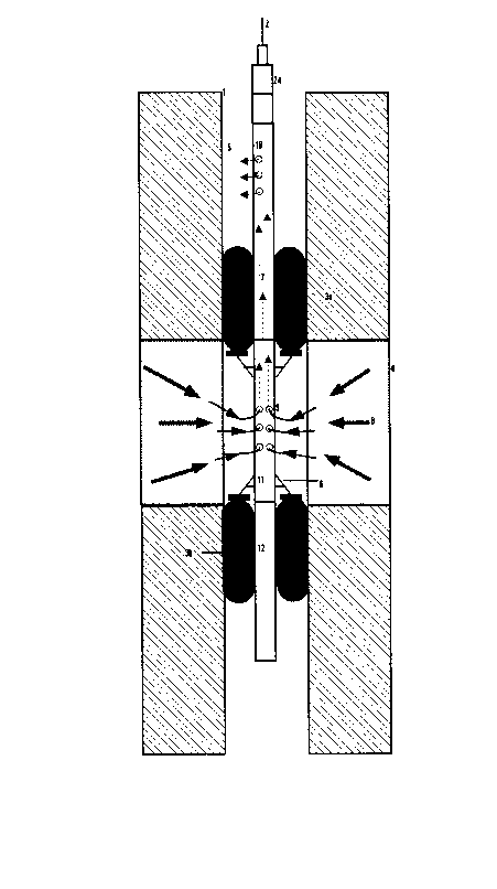
FIG. 1 is a side view of the downhole tool within a section of the wellbore. The packers
are inflated, sealing the desired section of wellbore. The formation fluids are drawn through the
tool by the pump, and thus a fluid flow rate test is depicted.
FIG. 2 is a schematic of the tool showing the relationship of the various components.
FIG.3 is a sketch of the packer support arms.
FIG.4 is a graph of simulated recorded data.
FIG.5 is a graph of bottom hole flowing pressure vs. gross production rate used to
130 determine reservoir performance.
DETAILED DESCRIPTION OF THE INVENTION
In FIG.l the tool is shown in the testing position in a wellbore 1 that penetrates
a subterranean earth formation. The tool is suspended in the wellbore by wireline logging cable
2. Inflated rubber packers 3a and 3b isolate a zone of interest of the earth formation 4 from the
wellbore fluids 5. Packer support arms 6 help prevent the rubber packers from failing due to large
differential pressures. A downhole pump located in the pump section 7 draws formation fluids 8
through the inlet 9 and exits them 10 above the upper most packer 3a. The ability exists to vary
140 the pump rate which produces the necessary flow rates. Corresponding pressure, temperature and
2U3~
fluid density values are measured instantaneously and sent uphole via the logging cable 2 where
they can be used to calculate the absolute open flow potential (AOF) of the zone of interest. Once
sufficient data has been obtained from a particular zone of interest, the pumping is stopped and
the packers deflated, and the tool can now be moved to another zone of interest and the test
procedure repeated.
The distance between the two packers can be set to any preselected value (at
surface) based on the zone of interest size and/or the desired test outcome. This is accomplished
by ch~nging the length of tool 11 between the packers.
A sample chamber 12 can be placed in the lower section of the tool and filled at1~0 any desired time from any particular zone of interest.
In FIG.2 a schematic of the tool components is shown. When the tool is positioned
over a particular zone of interest, the following would represent a typical sequence for performing
an AOF test:
(i) Equalizing valve V0 and flow line valve V2 are opened (all valves are closedprior to descending into the wellbore) allowing hydrostatic equalization across inflatable packer 3a.
(ii) Valve Vl is opened. The electric motor 13 is actuated and a low constant speed
is selected. The output shaft 14 of the electric motor is attached to a gear reduction system 15
effectively reducing the speed of the output shaft 16. The output shaft 16 turns the pump 17 and,
the speed of shaft 16 and the displacement of the pump in cubic m/min determines the displace-
160 ment rate or flow rate through line 18. Wellbore fluids are drawn through line 18 into the pump
17 and expelled through line 19 to the valve body 20. From the valve body the fluids are directed
through line 21 which is connected to packers 3a & 3b via line 22. Line 22 may be of various
lengths based on the variable packer spacing discussed earlier. As the pump continues to flow
wellbore fluids, the inflatable packers 3a ~ 3b start to inflate. As they inflate, packer support
arms 6 in FIG.3 are engaged by the expanding bladder material of the packer and become fully
engaged when the packers are fully inflated. This enables greater hydrostatic p-essules to be
withheld than by conventional inflatable packers because of the mechanical support. Complete
packer inflation occurs at a predetermined pressure and this is ascertained by pressure relief valve
~3~ 4
PVl which will prevent over pressurizing the packers. The pump is then stopped and valve Vl
170 is closed.
(iii) Equalizing valve V0 is closed and the zone of interest between the packers is
effectively sealed from the rest of the wellbore fluids.
(iv) AOF testing can now begin. Valve V3 is opened, this will allow fluids to beexpelled above packer 3a when the pump is actuated.
(v) The electric motor 13 is set to a low speed and the pump 17 draws fluid fromthe interval between the packers through port 9 and expels the fluid above packer 3a at port 10.
The speed of the pump is directly proportional to the pump displacement rate and hence flow rate.
This accuracy of measuring flow rate is uncommon in previous testing techniques. The
measurement of the formation plessule response occurs in the measurement section 23. There are
180 two pressure transducers Pl ~ P2 located here as well as a temperature sensor Tl and a resistance
sensor Rl. As fluid is drawn through the measurement section instantaneous plessule,temperature,
pump rate, differential plesswe and fluid resistivity are sent up to surface via the telemetry
cartridge 24 and logging cable 2. Fluid density can be determined from the differential pressure
and distance between transducers Pl & P2. This along with fluid resistivity provides the important
information to determine the fluid phases present during testing which is critical in determining
reservoir parameters accurately. This is an improvement over existing testing techniques.
(vi) Once the ples~ule response is determined to be satisfactory the flow rate can
be changed to another level. The sequence of ch~nging the pumping rate is repeated until enough
information is gathered to determine the AOF of the zone of interest. After the final flow period,
190 the pump is stopped and valve V3 is closed and the zone of interest is allowed to build up pressure
back to the reservoir pressure. A simulated test plot is shown in FIG.4. The instantaneous
plessule/time and flow rates are graphed here. As the pump rate increases in this example, the
corresponding pressure decreases. The build-up test is shown to start at point B and the final
build-up pressure is recorded at point C. Other presentation formats are possible i.e. fluid density,
temperature, fluid resistance etc.. and are only limited to ones desire.
(vii) Valve V4 can be opened after the build-up test and a representative sample
~Q34 ~4
of connate fluid from the zone of interest will flow through line 25 to the sample chamber 12.
This may occur by one of two ways:
(a) Either the formation has enough deliverability to fill the sample chamber itself,
200 or
(b) The pump 17 may be turned on which will draw connate fluids through line
18 into the pump and to the sample chamber via lines 19 & 25. This represents an improvement
in sampling techniques because the system does not rely on the formation to fill the sample
chamber. "Poor" performing reservoirs can still be drawn or "vacuumed" into the sample chamber.
In FIG. 5 the data that was acquired during the test period is graphed in another
way. This graph is a graph of bottom hole flowing ples~ule versus the gross production rate. By
simply extrapolating the graph to bottom hole flowing pressure = zero, the open flow potential can
be found at A. The graphical representation of results is not limited and can be presented in a
variety of forms and analyzed by those versed in the art of well testing.
210 As may be seen, therefore, the present invention has many advantages. Firstly, by
varying and accurately measuring downhole flow rates and pressure responses, a more accurate
indication of formation performance can be achieved now than with previous testing techniques.
Secondly, the ability to measure the different liquid phases during testing adds to the accuracy of
the testing technique. Thirdly, it provides versatility with the size of the zone of interest to be
tested in that the packer spacing may be selected as to the desired test outcome. Fourthly, the
packer support arms provide additional support for the packers, extending the hydrostatic
limitations of current packer designs. Fifthly, the downhole pump facilitates sample taking from
poor performing reservoirs. Sixthly, it provides a quick and economical way of deciding the
disposition of the wellbore. Seventhly, the method of testing is not limited to the type of borehole
220 encountered.
Various changes and or modifications such as will present themselves to those
familiar with the art may be made in the method and apparatus described herein without departing
from the spirit of this invention whose scope is to fall within these claims: