Note: Descriptions are shown in the official language in which they were submitted.
~0344~;0
PROTECTIVE HELMET
BACKGROUND OF THE INVENTION
The present invention relates to a protective head
covering, consisting mainly of a partial sphere-shaped
shell, fitted with an inner lining, to protect the
wearer from head injury in case of impact during
accidents. Such helmets are worn by race car drivers,
ski racers, motorcycle riders and the like and consist
of a shell, usually constructed from layers of resin and
l0 fibre and fitted with a foam inner lining, which is
shaped to conform tightly to the head of the wearer.
Such helmets may be constructed with or without an
integral chin strap part and may be equipped with or
without a transparent visor to cover the sight opening.
The impact absorbing qualities of the shell and
lining of such a helmet must meet very stringent
requirements and any improvement in this area is
therefore most desirous, especially when at the same
time raising the comfort level for the wearer.
Helmets using a resin and fibre constructed shell
are already well known. However, such conventional
shell construction relies only on surface curvature, as
dictated by the shape of the head, and the shell's resin
and fibre combination to provide the resilience and
25 necessary strength to withstand impact.
The construction method for such a shell usually
employs a mould into which layers of resin and fibre are
formed into the required shape. Hence, the shape of the
mould is entirely responsible for the forming and
30 layering of resin and fibre into the shape of the
finished shell.
SUMMARY OF THE INVENTION
It is therefore an object of the present invention
35 to provide a helmet shell, which, by way of its moulding
method, has increased resilience, strength and impact
resistance, without affecting the overall even thickness
and weight of the shell wall.
.. . .
: . : : , :
: .- ~ . .
2 ~0;~4450
It is another object of the present invention to
provide a helmet shell, which, by way of its moulding
method obtains an overall shell surface with reduced
drag resistance at all speeds, without affecting size
and dimensions of the helmet in general.
According to the invention there is provided a
protective helmet for race car drivers, ski racers,
motorcycle riders and the like, comprising a shell of
substantially spherical shape, constructed by way of a
10 moulding process, using bonded layers of resin and
fibre, to provide the necessary resilience and
resistance to impact, at a lowest possible weight to
strength ratio, wherein the bonded layers of resin and
fibre, instead of following directly the usual curvature
15 of the shell contour, create a series of small rises and
depressions, alternately and adjacent to each other
across the surface of the shell in a determined pattern,
and wherein a depression on the exterior of the shell
surface results in a rise on the interior of the shell
20 and vice versa, and whereas all rises or depressions are
preferably circular in shape and are arranged such,
that, when they are viewed in cross section in any
direction, appear as a continuous wave pattern or type
of corrugation, with such corrugation or embossing of
25 course to be generally known to increase rigidity and
resilience.
Furthermore, such moulded shell surface, in
addition to its increased strength, creates, when in
movement, certain improved air flow velocities across
30 its surface curvature and thereby aiding in the
reduction of drag normally existing at the rear of a
moving helmet. This reduction of drag results in less
lift and buffeting, which is especially problematic for
race car drivers, and eliminates a large amount of
35 pressure on the neck muscles of the wearer and generally
increases the overall comfort level. Ski racers might
experience enough reduction in drag to gain a winning
edge.
.
-:: , .
:: . . :. .
XU;~445~)
INTRODUCTION TO THE_DRAWINGS
Figure 1 of the drawings appended hereto depicts a
preferred embodiment of the present invention,
comprising a section through a resin and fibre layered
shell wall, as located in Figure 2 at 'A-A',
illustrating the corrugation arrangement with its
corresponding mould pattern;
Figure 2 of the drawings depicts a plan view of a
portion of the layered helmet shell, showing the pattern
10 of rises or depressions as appearing on the exterior
side of the shell;
Figure 3 of the drawings depicts a plan view of a
portion of the layered helmet shell, showing the pattern
of rises or depressions as appearing on the interior
15 side of the shell, corresponding to Figure 2;
Figure 4 of the drawings depicts a view of the
shell wall with its rises or depressions in a
combination of 'section through' and 'elevation beyond'
illustration;
Figure 5 of the drawings depicts a view of the
shell wall in section through location 'B-B' as
indicated in Figures 2 and 3.
Figure 6 of the drawings depicts a section through
the shell wall showing some alternative shapes of
25 depressions.
~ETAIL~ DESCRIPTION OF THE DRAWINGS
For the purpose of understanding the principle of
the present invention, reference will now be made to the
30 embodiment illustrated in the drawings and specific
language will be used to describe the same. It will
nevertheless be understood that no limitation of the
scope of the invention is thereby intended, such
alterations and further modifications in the illustrated
35 device, and such further applications of the principles
of the invention as illustrated therein being contem-
plated as would normally occur to one skilled in the art
to which the invention relates.
. . . ~ . .
..
;~0;~4450
Figure 1 of the drawings shows an elevated view
through a section of the helmet shell wall as located in
figures 2 and 3 at section line 'A-A', comprising resin
layers b and c imbedding fibre layer d within, evenly
following the corrugation contour line of the shell wall
as formed in mould a shown in view through a section.
This section view illustrates the arrangements of rises
and depression creating the shell wall's corrugation
effect, with depression h resulting in rise f and rise g
10 resulting in depression e on their opposite sides.
Increased shell wall strength can be obtained when fibre
layer d is imbedded always in the centre of resin layers
b and c, following all contour lines. In a resin and
chopped fibre application or injection type moulding
15 process, increased shell strength can be obtained by
maintaining even shell wall thickness following all
corrugation contour lines.
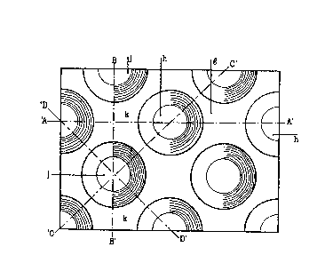
Figure 2 of the drawings depicts a plan view of a
portion of a helmet shell, representing the exterior
20 surface side of such a shell, showing depressions j and
h and rises g and k in an evenly patterned arrangement,
which, when viewed through section line 'A-A' present an
identical pattern as viewed through section line 'B-B',
and, when viewed through section line 'C-C' present an
25 identical pattern as when viewed through section line
'D-D'. Such even pattern exists all across the helmet
shell.
Figure 3 of the drawings depicts a plan view of the
same portion of helmet shell as viewed in figure 2, but
30 representing the interior surface side of that portion
of the shell. The pattern appears identical except for
depressions h and j, as appearing in figure 2, to be now
rises f and 1, and rises g and k, as in figure 2, now to
be depressions e and m. Depressions e and rise f
35 correspond to e and f as appearing in figure 1.
Figure 4 of the drawings dépicts a combination of a
view through section line 'A-A', as shown in figure 1,
and an elevated view beyond such section line view.
`
.
: .
~0~ 4so
This illustrates the corrugation effect using the even
shell wall thickness p to increase the overall shell
wall dimension to q, increasing shell strength without
considera~ly increasing weight or material of such shell
construction. Dimension q is the distance between
points g, gl and g2 etc. and points f, fl, f2.
Figure 5 of the drawings depicts an elevated view
through section line 'B-B' as indicated in figures 2 and
3, and illustrates the identical corrugation pattern
10 effect when compared with view through section line 'A-
A', where points k and j and points m and 1 correspond
with points g and h and points e and f, as in figure 1,
respectively.
Figure 6 of the drawings depicts a section through
lS the shell wall illustrating a different corrugation
pattern, where depressions k and j and rises m and 1
show alternate shapes to the shapes shown in figure 5.
.
', ': '
~ ~;, .. . . , , ,,, . -
: . . . . .