Note: Descriptions are shown in the official language in which they were submitted.
2 ~ ~ L~
15-CT-3331
W. ~ el
~OW-TIE X-RAY FILTER ASSEMBLY
FOR DUAL ENERGY TOMOGRAPHY
This invention relates to x-ray filters for controlling
the energy of an x-ray beam and specifically to filters used
in x-ray computed tomography systems for making dual energy
measurements.
Computed tomography (CT) systems typically include an x-
ray source collimated to form a fan beam directed througA an
object to be imaged and received by an x-ray detector array.
The x-ray source, the fan beam and detector array are
oricntated to lie within the x-y plane of a Cartesian
coordinate system, termed the "imaging plane". The x-ray
source and detector array may be rotate!d together on a gantry
within the imaging plane, around the imaged object, and hence
around the z-axis of the Cartesian coordinate system.
The detector array is comprised oi.- detector elements
each of which measures the intensity ol transmitted radiation
along a ray path pro~ected from the x-r.ay source to that
particular detector element. At each gantry angle a
projection is acquired comprised of int:ensity signals from
each of thc detector elements. The gantry is then rotated to
a new gantry angle and the process is repeated to collect an
number of projection~ along a number of gantry angles to form
a tomographic projection set. Each acquired tomographic
projec~ion set may be stored in numerical form for later
computer procesqing to reconstruct a cross sectional image
according to algorithm~ known in the art. The reconstructed
image may be displayed on a conventional CRT tube or may be
converted to a rilm record by mea~s of a computer controlled
camera. -
The x-ray source is typically comprised of an evacuated
glass x~ray tube containing an anode and a cathode. X-rays
. .
,
.. . ~
.. -
~3~'17~
15CT-3331
--2--
are produced when electrons from the cathode are accelerated
against a focal spot on the anode by means of a high voltage
across the anode and cathode.
The spectrum of the x-rays produced encompasses a band
of radiation of different frequencies and hence different
energies. The short wavelength radiation of higher energy is
referred to as "hard" x-ray radiation and the longer
wavelength radiation of lower energy is referred to as "soft"
x-ray radiation. The very lowest energy x-rays are almost
entireLy absorbed by the body and therefore provide little
contribution to the x-ray image. Nevertheless, these soft x-
rays contribute to the total exposure of the patient to
harmful ionizing radiation. Accordingly, these rays are
usually removed by a filter incorporated into the x-ray tube,
a~ is known in the art.
The x-rays emitted by the x-ray tube may be subjected to
two additlonal filters, a "spectral" filter and an
"attenuation" filter.
The spectral filter may be a molybdenum strip which
serves ~o harden the x-ray beam by further removing longer
wavelength, lower energy x-rays. This spectral filter may be
moved in and out of the beam of x-rays and hence provides the
ability to image an object with x-ray beams of different
spectral composition. The construction of x-ray images from
two or more images taken with x-ray beams of different
spectral composition is termed "dual energy scanning" and
finds considerable use in the imaging of soft tissue where
single energy scanning may only provide limited contrast.
The spectral filter may be equipped wi~h a track or hinge to
permit its introduction and removal from the x-ray beam.
In addition to the spectral filter, the x-rays m~y be
subjected to an attenuation filter. The at~enuation filter
is ordinarily a synthetic polymer such as Teflon having an x-
ray absorption spectral characteristic near to that of wa~er
~ ~ 3 ~ ~ 7 ~
15CT-3331
and hence the human body. This filter is not intended to
adjust the spectral characteristics of the x-ray beam but
rather to compensate for the variation in thickness of the
imaged body The x-rays that pasr~ through the center of the
imaged body, ordinarily the thic~est part, are least
attenuated by this filter whereas the x-rays passing through
the edges of the imaged body, ordinarily the thinnest part
are more attenuated by this filter. The xrays that are not
intercepted by the body at all are maximally attenuated by
this filter, ideally by an amount equal to that of the x-rays
passing through the center of the body. The result of this
selective attenuation is that the x-rays striking the Ct x-
ray detectors are of similar energy and centered around the
middle of the detector's sensitlvity. rrhe attenuation filter
therefore may allow the use of more sensitive x-ray detectors
reducing the range of x-ray energies.
For purposes of calibration it is ordinarily desirable
that the attenuation filter may be removed from the path of
the x-ray beam. Thiq may b~ accomplished by positioning the
attenuation fllter on a movable track.
As mentioned, the attenuatlon filter may be constructed
of a synthetic polymer such as Teflon so as to closely match
the absorption characteristics of the imaged body. Although
the absorption characteristics of such polymers may be
rPlatively stable, under continued x-ray exposure the
mechanical characteristics o~ the polymer change. The color
of the ma~erial may darken and cracks may develop. The
discontinuity of the x-ray beam introduced by the cracks may
cause severe image artifacts and thus require the replacement
of the filter. Such replacement may be both inconvenient an~
costly.
.
~ ~ 3 l~ L~
_4_ 15CT-3331
Although the applicant does not wish to be bound by a
particular theory, it is believed that the cracking of the
attenuation filter under continued use is caused by a
combination of the embrittlement of the polymer of the
attenuation filter through a breaking down of the polymer
molecules by the x-ray beam, together with stresses set up
between the attenuation filter and its support as they expand
from the heat of the adjacent x-ray tube.
According to the present invention, therefore, the
attenuation filter is mounted to reduce expansion induced
stress. Specifi.cally, the filter element for the attenuation
filter is attached to a movable support plate for positioning
the filter element within the x-ray bea~m. The center of the
filter element is affixed to the support plate but the ends
are attached to slide with change~ in t:emperature and thus
with changes in the dimensions of the iilter element and the
support plate.
In one embodiment, the ends of the filter element are
fitted with holes and are held with a fastener having a shanX
diameter less than the diameter of the holes. The difference
between the shank and hole diameter is equal to a
predetermined expansion distance. ~he filter element is held
against the ~upport plate by a compresqion spring positioned
between the hea~ of the fastener and the filter.
It is one object of the invention to permit the ends of
the filter element to slide a~ the filter element expands
with respect to the support plate thus avoiding ~he qtress
that might cause the filter element to fracture as it becomes
brittle with more x-ray exposure. The compression spring
pushes the filter against the surface of the support plate
:
.~ :
~3dL~7
l5CT-3331
but permits the filter to slide along the surface of the
support plate as it expands.
It is another object of the invention to reduce image
artifacts caused by shifting of the filter. The fixing of
the filter along its center line permits the expansion of the
filter toward either end without shifting of the entire
filter toward either end. In one embodiment, the center of
the filter element is attached to the support plate by means
of an attachment wall. A hole in the attachment wall
prevents the formation of stresses on the attachment as a
result of expansion of the filter element ln a direction
perpendicular to its two ends.
In yet another embodiment, a second filter is attached
to the support plate so that at a first support plate
position the x-ray beam ls attenuated by both the first and
second filter element and at a second support plate position
the x-ray beam is attenuated by only one f~lter element. The
second filter is attached to the support plate so as to
tension the first filter with relative expansion of the
support plate.
It is thus another object of the invention to provide a
method of incorporating the spectral filter with the
attenuation filter so as to provide positive positioning of
bo~h. The ~ensioning of the spectral filter upon relative
expansion of the support plate ensures that the spectral
filter is no~ place under compression when cool which might
lead to bucking. The spectral filter is fixed with respect
to the attenuation filter and the entire filter assembly is
moved in and ou~ of the x-ray beam providing more accurate
posi~ioning of the spectral filter.
Othex objects and advantage~ besides those discussed
above shall be apparent to those experienced in the art from
the description of a preferred embodiment of the in~ention
which follows. In the description, reference is made to the
: -. . : . .
:::
~ o ~ rl bi
-6- 15CT-3331
accompanying drawings, which form a part hereof, and which
illustrate one example of the invention. Such example,
however, is not exhaustive of the various alternative forms
of the invention, and ~herefore reference is mad~ to the
claims which follow the description for determining the scope
of the invention.
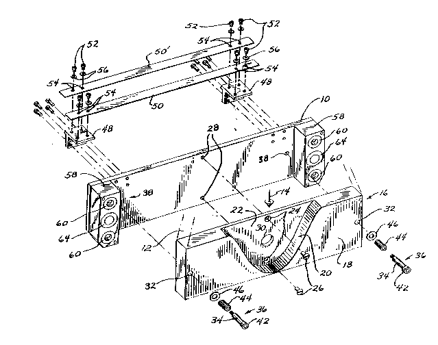
Figure 1 is an exploded perspective view of the filter
assembly showing the relative positions of the attenuation
filter, the support plate and the spectral filters;
Figure 2 is a partial cutaway plan view of the filter
assembly showing the mounting of the at:tenuation filter to
the ~upport plate; and
Figure 3 is a plan view similar to that of Fi~ure 2,
showlng the mounting of the filter assembly on the drive
mechanism for mo~ing the filter assemb:Ly within the x-ray
beam.
D~ rb~
Referring to Figure 1, a generally rectangular
support plate 10 is positioned edgewise to a fan bean of x-
rays 12 radiating vertically along axis 14. Attached to
one face of the support plate 10 is an attenuation filter
16 comprised of a corresponding rec~angular filter block 18
of Teflon. It will be apparent to those of ordinary skill
in the art that other similar materials may be used for the
attenuation filtex 16. I~ the exposed face of the filter
block 18 is a do~nward extendins saddle notch 20 centered
within the filter block i8 bu~ le~s than the full width of
the filter block 18 so as to leave intact a supporting wall
22. The saddle notch 20 reduces the thickness of the
a~tenua~ion filter 16 along the path of the projected fan
~03~
15CT-3331
-7-
beam of x-rays 12 so that the thickness of the attenuation
filter 16 correspond inversely to the thickness of a
typical object being imaged (not shown). That is, the
attenuation filter 16 is thinnest in the center to
attenuate least those x-rays 12 that will pass through the
thickes~ portion of the imaged object, and thickest at
either edge to attenuate most the x-rays 12 which pass
without any attenuation on either side of the imaged object
As mentioned above, the purpose of the attenuation filter
16 is to equalize, approximately, the intensity of the x-
rays 12 received by a CT detector and hence to permit
improved detector sensitivity.
The supporting wall 22 exposed by the saddle notch 20
contains two vertically disposed countersunk holes 24.
Referring both to Figure 1 and 2, the elttenuation filter 16
is attached to the support plate 10 by means of flathead
machine screws 26 fitted within countersunk holes 24 and
received by corresponding tapped hole~ 28 at the center of
the support plate 10. The attenuation filter 16 is thus
fixed to the ~upport plate 10 along the~ vertical line of
symmetry of the support plate 10 and the attenuation filter
16. The interfitting faces of the flathead fasteners 26
and the countersunk holes 24 in the supporting wall 22
serve to prevent the shifting of the center of the
att~nuation filter 16 with respect to the support plate 10.
During use of the CT machine, the x-ray tube (not
shown) releases considerable hea~, heating the attenuation
filter 16 and support plate 10 by up to 50F above the
ordinary room temperature. The expansion of the
attenuation filter 16 will differ from that of the support
plate 10 depellding on the materials from which each is
cons~ructed. With a Teflon atte~uation filter and an
aluminum support plate, the coe~flcient of expansion are
approximately 80xlO-S inches/inch-F and 13x10-6
- ~ . ,: :,, , i ,
.
~ ~ 3 ~
-8- 15CT-3331
inches/inch-F respectively. The difference in expansion
over 50F will therefore be approximately 3 thousandths or
an inch per inch of mat~rial.
A stress relief hole ~0 is cut in the supporting wall
S 22 of the attenuation filter 16 between the countersunk
holes 28 to relieve stress caused by vertical expansion of
the filter block 18 and the supporting wall 22 as it is
heated by the adjacent x ray tube (not shown). The
distance between the mounting points of the supporting wall
24, i.e. the distance between the countersunk holes 24 is
approximately 2 inches and hence 6 thousandths of an inch
of expansion is accommodated by the stress relief hole 30.
The stress relief hole deorms from a circle to an ellipse
to prevent buckllng of the supporting W2l11 between the
lS countersunk holes 24 with relative expansion of the filter
block 18 on the support plate 28.
Horizontal expansion of the filter block 18 is
considerably greater than the vertical expansion, described
above, a~ a result of the greater length than he~ght o~ the
filter block 18. For example, the lengt:h of the filter
block may be 10 inches and hence approxlmately 30
thousandths of an inch of horizontal expansion may be
expected wlth the previously described conditions and
materials.
This hori20ntal expansion of the filter block 18 is
accommodated in a different manner than the vertical
expan3ion. Oversized holes 32 are drilled through the face
of each end of the filter block 18 to permit the insertion
of the shank 34 of shoulder screws 36 which are received by
corre~ponding tapped hol-es 38 in the face of the support
plate 10 a~ either end of the support plate 10. The
shoulder screws 36 are sized so that when the shoulder 40
of the shoulder screws 36 abut the face of the support
plate lQ, the shank 34 of ~he shoulder screws 36 extends
,.
.
_9_ 15CT-3331
beyond the o~ter face of the filter block 18 ~nd the heads
42 of the shoulder screws 36 are displaced from the outer
face of the filter block 18. A compression spring 44 is
placed between the head 42 of each shoulder screw 36 and
the outer face of the filter block 18. The compression
spring 44 is sized so that it is compressed when the
shoulder screw 36 is fully engaged with the support plate
10 and hence the compression spring 44 exerts an inward
force on the fllter block 18 holding it against the support
plate 10. A washer 46 is placed between the compression
spring 44 and the filter block 18 to spread the force of
the compression spring 44 and reduce any cold flow of the
material of the filter block 18.
The oversized holes 32 are of greater diameter than
the shanks 34 of the shoulder screws 36 by approximately 60
thousandths of an inch to accommodate the 30 thousandths of
an inch expansion of the filter block 18 along its
horizontal dlmension of approximately 10 inches. The
compression spring 44 exerts only a normal force on the
filter block 18 and hence does not resist the expansion of
the attenuation filter 16 but affects only the sliding
friction between the at-tenuatlon filter 16 and the support
plate 10. This sliding fric~ion is ordinarily low.
Referring again to Figure 1, two T-brackets 48 are
attached to the top edge of either end of the support plate
10 by means of a vertical leg of the T-bracket 48. The ~wo
horizontal arms of each T-bracket 48 each support one end
of two parallel metallic filter strips 50 and S0' used as
spectral filters. The ends of the filter strips 50 and 50'
are secured to the horizontal arms of the T-brackets 48 by
means of two machine screws 52 passing through holcs 54 in
the ends of the filter strips S0 and S0', and the
horizontal arms of the T-brackets 4~, and are secured with
lock washers 56. The filter strips 50 and 50' are given a
.
`
.. , . :
.. .: ' ~ .' :
2 ~ 7 ~
-10- 15CT-3331
slight tension during assembly at room temperature to
prevent buckling in cooler environments.
The filter strips 50 and 50' may be formed of
molybdenum and will have a lower coefficient of expansion
that an aluminum support plate 10. Specifically, the
coefficient of expansion of molybdenum is approximately
3x10⁻⁶ inches/inch~F versus 13x10-6 inches/inch-F for an
aluminum support plate 10. The difference in expansion
over 50F will be approximately 0.5 thousandths of an inch
per inch of materiaL.
This expansion is accommodated by ensuring that the
filter strips 50 and 50' do not slip with respect to the
support plate 10 as both are heated and cooled and hence
that the filter strips 50 and 50' are constantly in
tension. Under tension, the filter strips 50 and 50' will
not buckle. Unlike the polymer material of the attenuation
filter 16, the metal filter strips 50 alnd 50' are not
significantly embrittled with x-ray exposure and hence
small amounts of s~ress may be accommoclated.
One filter strip 50 is positioned above the
attenuation filter 16 so a~ to shield one half of the
attenuation filter's thickness from exposure by the x-ray
fan beam 12. The other filter strip 50' extends from the
rear of the support plate 10 away from the attenuation
filter 16 and over unobstructed space. This configura~ion
permits selective combinations of the attenuation filter 16
and the filter s~rips 50 and 50' as will be described
below,
Referring to Fiqure 1, pillow blocks 58 are attached
to the face of suppor~ pLate 10 at either end of support
plate 10 beyond ~he extent of the filter block 18.
Positioned within holes in the pillow blocks 58 at the
corners of the support plate 10 are threaded inserts 60
which receive lead~ screws 62 aq will be described later.
.
:, ` ,
.
2 ~ s~ 6
~ 15CT-3331
Also within each the pillow block 58 centered between the
threaded inserts 60 is a linear bearing 64 which receives a
guide shaft 66 on which the pillow blocks 58 and the
support plate 10 may move.
Referring now to Figures 2 and 3, lead screws 62
corresponding to the positions of threaded inserts 60
project from a motor drive plate 68 aligned with and
parallel to the support plate 10. The lead screws are
supported on the motor drive plate 68 by bearings 70 and
are received by each of the threaded inserts 60 Two guide
shafts 66 (only partially visible in Figure 3) are
similarly received by the linear bearings 64 and hold the
weight of the support plate 10 as it moves toward and away
from the motor drive plate 68 with motion of the lead
screws 62.
The lead screws 62 are moved synchronously to ensure
positive and parallel motion of the support plate 10 with
respect to the motor drive plate 68 and the area of the fan
beam of x-rays 12. This motlon iq accomplished by means of
sprocket wheels 72 attached to each of the lead screw 52
near the motor drive plate 68 and connected together by a
loop of roller chain 7~. A drive sprocket wheel 76 i~
attached to a shaft of a stepper motor 78 which may be
moved along the motor drlve plate 68 by means of adjustment
bolts 80 so as to remove a~y slack from the loop of roller
chain 74 a is generally understood in the art.
The stepper motor 78 is controlled by a solid state
stepper motor controller 82 which respond to digital
signals, indicating direction and s~ep number of steps, to
move the shaft of the stepper motor 78 a certain number of
degxees in either direction. The relative movement of the
support plate la and hence the attenuation filter 16 and
the filter strips 50 and S0' may be calculated from the
pitch of the lead screws 62 and the number of degrees
' ` ` ,
, ~ :
' '
7 ~
15CT-3331
-12-
stepped by the stepping motor 78. The absolute position of
the support plate 10 is determined by turning the lead
screws 62 so as to draw the support plate 10 toward the
motor drive plate 68 until the plunger of a limit switch 82
attached to the motor drive plate 68 is depressed by the
face of the attenuation filter 16 facing the motor support
plate 68. The depression of the plunger of the limit
switch 82 indicates that the support plate 10 is in a known
location. Future positions of the support plate 10 then
may be determined by tracking the subsequent relative
movements of the stepper motor 78.
Referring still to Figure 3, the support plate 10 may
be positioned in one of four locations with respect to the
fan beam of x-rays 12. In the first location, the support
plate 10 is furthest from the motor dri.ve plate 68 and
Region A is aligned with the fan beam l.2 so that neither
the attenuation filter 16 nor either fi.lter strip 50 or 50'
intercepts the fan beam 12. In the sec:ond location, the
support plate 10 moves closer to the motor drive plate 68
so that Region B is aligned with the f2m beam 12 and the
attenuation filter 16 alone is in the path of the fan beam
12. In the third location, the support plate 10 moves yet
closer to the motor drive plate 68 so that Re~ion C is
aligned with the fan beam 12 and both the attenuation
filter 16 and a ilter strip 50 are in the path of the fan
beam 12. Finally, in the fourth location, the support
plate 10 moves further toward the motor drive plate 68 so
that only th~ filter strip 50' is in the path of the f an
beam 12.
Thus the stepper motor 78 may be used to vary the
filtration of the x-ray fan beam 12 by moving the support
plate 10 appropriately.
The above description hac been that of a preferred
embodiment of the present invention. It will occur to
- : .
'
.
., : . , ' . - ~ ~
- .
1 7 ~
-13- liCT-3331
those who practice the art that many modifications may be
made without departing from the spirit and scope of the
invention. For example, the attenuation filter 16, the
filter strips 50 and 50' and the support plate 10 may be
S constructed of other materials as known in the art with
different coefficients of expansion than those described
herein In order to apprise the public of the various
embodiments that may fall within the scope of the
invention, the following claims are made.
. - . . .
'. ''
', , ,
.: . . . .
' ~