Note: Descriptions are shown in the official language in which they were submitted.
WO 9l/00623 ; . pcr/usso/p3l3~7~ ,, .
BATTERY CHARGING ~Y~i'l'~;M
203449~
Ra~k~round of the Inven~ion
This invention relates generally to a system of charging
rechargeable batteries and more particularly to a battery
10 charging system for a lithium electrode rechargeable
battery which may be incomr~t;ble with early battery
chargers.
Battery chargers usually contain all the circuitry
1 5 needed to charge a battery except for s~n~ing devices such
as thermistors. Batteries typically cont~in no electrical
circuitry except for sensing devices such as thermistors or
type determining circuitry such as that described in U.S.
Patent Application No. 341, 778, "Method and Apparatus for
2 0 Determining Battery Type", filed on behalf of Johnson et al.
on 04/21/89. However, it has been noted that some 3esi~ners
have placed some active ci,cuil" ~ within the battery housing
primarily to protect the electrochemical cells from ~l~m~ge
due to accidental short circuits during transport or use.
Rechargeable batteries employing a lithium electrode
generally provide a greater energy storage capacity per unit
volume than other commercially available batteries used in
portable products. A lithium battery is a desirable addition
3 0 to such a portable product. Lithium batteries, however,
have charging characteristics which are different than
other types of rechargeable batteries.
- --WQ Q1/00623 2 0 3 4 ~ ~ O PCI/US90/03137
r ~
; - 2
~ s ~
When a new battery type becomes available, full
comp~tibility between currently available battery
chargersand the new battery type i8 usually not present; the
new battery type cannot be optimally charged by the
chargers optimized for previously existing battery types.
Other charging systems exist using batteries which
cont~in additional ci~cuilly within the battery housing to
accomplish temperature sensing of the electro~hemic~1
cells, which is coupled to me charger circuitry for
modification of the charter perform~nce. Any additional
current drain placed on the battery by this circuitry causes
reduced storage life for the battery. In order to reduce this
additional current drain, expensive low power circuit
element~ have been used.
~urnm~ry of the Invention
Therefore, the present invention solves the problem of
2 0 battery and charger jncomp~tibility by providing circuitry
for regulating charging within the battery itself and has the
circuitry active only when the battery is in the charger and
deriving its power from the charger.
2 5 Accordingly, it is one object of the present invention to
detect an over-discharge condition and lJlevellt the battery
from being charged when it has been over-tli.sch~rged.
It is another object of the present invention to detect
electrochemical cell imbalance within the battery and
3 0 prevent the battery from being charged when there is an
imbalance.
Wo 9l/00623 2 o 3 4 4 9 o Pcr/US9o/03l37
It is a further object of the present invention to reset the
battery charge prevention if the battery electrochemical cell
or cells are healed.
,~
5 Brief nescri~tion of the 1 )r~wir~s
Fig. 1 is a schem~tic diagram of a conventional battery
charger.
Figure 2 is a sçhem~tic diagram of the battery and
1 0 associated circuitry in accordance with the present
invention.
T3etailed 1 )escri~tion of the Preferre~ F,mho(liment
1 5 The invention disclosed herein is of a battery charging
system. It can be used on different types of batteries but in
the preferred embodiment it is for use with lithium batteries
and provides backwalds co np~tibility with existing battery
chargers ~esigne-l for nickel-cad~iu or other types of
2 0 rechargeable batteries. It is ant;~ip~terl that batteries
employing the present invention will be used for portable
radiotelephone equipment such as cellular portable
radiotelephone model number F09HGD8453AA av7.il~qhle
from Motorola, Inc.
Fig. 1 is a schematic of a collvelltional battery charger
having the capability of charging convention~l batteries. A
more complic~te~l battery charger such as that described in
U.S. Patent Application No. (docket CE00132R), "Multiple
3 0 Battery Multiple Rate Battery Charger", filed on behalf of
Johnson et al. on 05/3V89 may also be used. In Fig. 1, a
transformer 101 may be a direct plug-in wall mount
transformer unit provides an AC ou~u~ to supply power to
-
WO 91/00623 PCI/US90/03137
4 ~ 2 0 3 4 ~ 9 0
the charger. This AC output causes rectifier diode 103 to
conduct on half of the AC cycle. When diode 103 conducts,
the capacitor 105 charges. The energy stored in capacitor
105 allows for charging during the half of the AC cycle
5 when the diode 103 is not conducting. The charging current
is determined by the effective resistance between c~p~r,itor
105 and the charging termin~l~ 107 and 109. When a battery
is present in the charger and current begins to flow into the
charger positive terminal 107 through the LED (light
1 0 emitting diode) indicator 111 and resistor 1i3. Additional
charging current is supplied through resistor 117.
The charger circuitry of Fig. 1 is merely a source of
charging current and will continue to source current to any
1 ~ battery coupled to it. A battery having the circuitry shown
in the schematic of Fig. 2 provides a built-in int,P!lligence to
protect and properly charge a battery which is particular
about the type of charge it rece*es. This intelligence
includes: (1) Voltage Cutoff: in which the charging of the
2 0 battery will be termin~ted when the battery voltage exceeds a
threshold. In the preferred embo~iment~ this threshold is -
7.2 volts. (2) Hysteresis: Once the charging is termin~ted,
the voltage at the termin~l~ of the electrochemical cells will
drop and unless there is hysteresis the charger will osrill~te
2 5 in and out of charge. The hysteresis of the preferred
embocliment will disallow charge until the battery positive
voltage is reduced to ~lox;m~tely 6.2 volts. (3) (~ontact
Debounce: If the battery were to see intermittent coT-~rt
with the charger terminAl~, charger + power may be
3 0 removed for a moment and the hysteresis may be reset.
Using a charged up capacitor, contact bounces of at least
one second in duration will not reset the hysteresis. (4) Over- A
rhz~rge charge disable: With lithium batteries, if the
WO 9l/00623 Pcr/us90/03137
~- 5 2~3~49~ ~
cells are over-discharged or if they are l~mAged, repeated
charging may cause a possible safety problem. Charge is
denied when the battery is over-discharged. In the
5 preferred embodiment this condition is es~hli.~hed when
the battery voltage is 3.5 volts or less. (5) Cell string
imbalance charge disable: When near the end of the life of a
cell the cell's voltage becomes subst~nt,iAlly reduced with
respect to the other cells in the battery; the battery develops a
1 0 potential safety problem. Charge is disabled to avoid abuse
when the defective cell voltage is less than 40% of the total
cell string voltage.
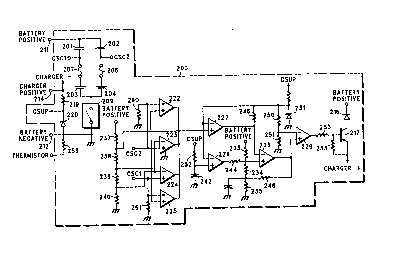
F'ig. 2 is an electrical schemAtic of the circuitry disposed
1 5 within a battery housing 200, shown in broken line in the
schematic. The lithium electrochemical cells 201, 202, 203,
and 204 of the preferred embo-liment are assembled in a
series-parallel coTnhinAtion of two cell strings. At the center
of each cell string is a thermal fuse 206, 207 which is
2 0 thermally coupled to its associated series-co~necte~l cells to
provide protection for the cells 201-204. If the cells 201-204
reach a temperature greater than the trip point of the
thermal fuses (207 or 207) will open and the cells will be
discorlnected from use. The two cell strings are run
25 through a current-activated circuit breaker 209, commonly
known as a "polyswitch" available from Raychem, Inc.,
which will trigger under short circuit conditions across the
BATTERY POSITIVE t~llllil.al 211 and the BATTERY
NEGATIVE terminal 212 on the outside of the battery
3 0 housing 200. The center points of each series-parallel cell
string are denoted by CSC1 or CSC2.
The CHARGER POSITIVE terminal 214, which appears
on the outer surface of the battery housing 200 is internally
J
-
WO 9l/00623 Pcr/usso/o3l3~
6 2034490
connected to and denoted by C~harger +. When the battery is
being charged from a battery charger circuit like that of Fig.
1, the charge current is p~se-l to the electrochemical cells
201-204 through a diode 216 and a transistor switch 217. The
charge current is also connecte-l to a resistor 219 and to
charger supply line CSUP which supplies power to operate
the internal circuitry from the charger rather than from the
electrochemical cells 201-204. A Zener diode 220 is used to
1 0 protect the circuitry from voltages in excess of the electrical
parts ratings.
When the battery is not present in a charger, there is no
power supplied to (:~harger +. In this condition, all the
comp~rators 222, 223, 224, 225,226, 227, 228, and 229 (which
1 5 may be comparator type number LM2901D available from
Motorola, Inc. having PNP input junctions) do not have a
power supply and are essentially in an off state because,
king a power supply input, they eæs~nti~lly draw no
current. ~imil~rly, the conventional voltage reference 231
2 0 (which in the preferred embodiment is a 2.5 volt reference)
also draws no current. Therefore all the active circuitry
draws no current when the battery is not in the charger.
However, there are two resistor dividers which draw a
small amount of current from the electrochemical cells.
2 5 First is the series connection of resistors 233, 234, and 235.
This resistor divider uses high value resistors to minimi~e
the current drain from the battery. The other resistor
divider is that forrned by resistors 237, 238, 239, and 240,
which also minimi7:es the amount of current by using high
3 0 value resistors. Because the active devices do not draw any
current from the electrochemical cells and the comparator
inputs are PNP junction inputs, the present invention
minimi7eS the amount of power that is drained from the
Wo 9l/00623 Pcr/usso/03l37
7 ~ ~ 0 3 ~ ~ 9 ~
battery when the battery is not being charged. This feature
gives the battery greater storage life. In the case of a battery
employing a lithium electrode in the electro~hemic~l cells,
5 the additional circuitry of the present invention does not
degrade the shelf life subst~nti~lly.
The circuitry within the battery housing 200 is used
when the battery is placed into the charger, the c~p~-~itor
1 0 242 is at zero volts relative to commor-, initially holding the
positive input terminal of compArator 226 low relative to the
inverting input which is connected to the voltage reference
from reference 231. This initial condition gives a "low"
output ~ign.ql. Because the output is low, the signal
1 5 provided via series resistor 244 and shunt resistors 234 and
236 drives the non-inverting input of comp~rator 228 low.
The inverting input terminal of comparator 228 is connected
to the voltage reference 231 through resistor 246. The
resistor 244 is chosen so that the voltage at the non-i,lve~ ~ing
2 0 input of comparator 228 will be below the voltage reference
231. This creates a "false" condition wherein the output of
the comparator 228 goes low. When the output of
comparator 228 is low, the resistor 248 is ess~nti~lly placed
in parallel across resistor 235 further re~ inF the voltage
2 5 at the non-inverting input of comparator 228.
Since the battery has been placed in the charger, the
initial (non-charged) condition across capacitor 242 will
change. Capacitor 242 charges with a time constant
3 0 determined by its capacity and resistor 252. When the
voltage across capacitor 242 exceeds the value of the voltage
from voltage reference 231, the output of comp~rator 226
becomes an open circuit. This open circuit essqnt~ y
WO gl/00623 PCr/USso/03l37
8 ~ 4 9 ~
removes resistor 244 from the circuit so that the voltage at
the non-inverting input of comr~rator 228 increases. This
sequence of events sets the resistor divider of resistors 23,
234, and 235, in parallel with resistor 248. When the voltage
at the termin~l~ of the electroçh~mic~l cells 201-204 is such
that the voltage at the non-illvel ling input of comr~rator 228
exceeds the reference voltage supplied by voltage .efelellce
231, the electro~hemic~l cells of the battery are deemed to be
1 0 fully charged.
In the preferred embodiment employing lithium
electrode cells, this happens when the battery has an output
voltage across terminAl~ 211 and 212 of a~l,.oxi..~tsly 7.2
1 5 volts. VVhen the battery charges above 7.2 volts the input at
the positive terminal comparator 228 is greater than the
reference voltage, the output becomes an open circuit, and
resistor 248 essentially is icol~ed from the resistor divider of
resistors 233, 234, and 235. Thus, the voltage at the positive
2 0 terminal of comparator 228 increases. This provides a
hysteresis effect so that one the circuit switches and the
battery stops being charged, the circuit does not oscillate
back and forth as the battery voltage settles.
When the output of comparator 228 becomes an open
2 5 circuit, the voltage at the non-inverting input of comr~rator
229 is essenti~lly the divided down voltage present at the
node between resistors 234 and 235. This voltage is
compared against the divided down Lefe.~llce voltage from
reference 231 (by resistors 250 and 251 with the common
3 0 point between them driving the illVt:l lillg input of
comparator 229). When the o~ u~ voltage of comr~rator 228
(the voltage at comparator 229 non-illvel ling input) is
greater than the voltage at the inverting input of comp~rator
WO 91/00623 PCI~/US90/03137
_
~ 9 20~4490
229, a "true" condition is created and comparator 229 output
becomes an open circuit. When the output of comparator
228 is low, the non-inverting input of comparator 229 is low.
When the outputs of these comp~rators are low, they will
sink current. Thus, when the oul,l ul of cQmr~rator 229 is
low, current will be drawn from the base of the tr~n~istor
217 through resistor 253, thereby turning transistor 217 on.
When it is on, current will flow from the Charger + line
1 0 through the transistor 217, through diode ~16, and into the
electrochemical cells 201-204 to charge them. When the
output of comp~rator 229 is open, there will not be base
current flowing through resistor 253 and tr~n~i~tor 217 will
be off and the electroch~mic~l cells will not charge. Resistor
1 5 255 provides pull-up for the base of transistor 217 when the
output of comparator 229 is open to insure that the
tr~n~i~tor 217 is off. The diode 216 ~ v~nts the
electrochemical cells from ~Lai-li,lg back through the
transistor 217 when the battery is not in a charger.
2 0 Zener diode 220 is coupled in series with resistor 219 to
create the supply line of CSUP. CSUP is limited to the Zener
voltage so ~SUP to the co...p~. ators will not exceed their
m~imum ratings.
In accordance with one feature of the present inveIltion,
2 5 the battery may automatically be ~. ~vented from accel.tillg
charging current if the voltage available from the
electroch~mic~l cells is below a threshold voltage. This low
voltage threshold (determined by the l~hemi.stry of the
lithium system in the ~lefel-~ed embo~liment) can be
3 0 re~che~ if the battery is over-charged. At this voltage, the
electrochemical cells have most likely been ~m~ged and
the safety of the battery may be col--p,vmised. To
~ccomE-lish an automatic removal of the electro~hamicsll
WO 9l/00623 Pcr/usso/o3l37
cells, a voltage detection circuit is employed in the preferred
embodiment. Comparator 227 is used to disable the
charging of an over-~i.cch~rged battery. This is
accomplished by using the voltage from voltage reference
231 driving the inverting input of comr~rator 227 and a
divided-down voltage derived from the resistor network of
resistors 237, 238, 239, and 240 and voltage coupled form the
BAl~ERY POSITIVE terminal 211. The node between
1 0 resistor 237 and resistor 238 is coupled to the non-inverting
input of comp~rator 227 such that when, in the preferred
embo-liment the battery voltage goes below appro~im~tely
3.5 volts, the output of comparator 227 goes low. Upon this
occurrence the reference voltage is effectively removed from
1 5 the inverting input of comparator 228. This causes the
output of comparator 228 to become an open circuit, turning
off comparator 229, turning off the transistor 217 and
stopping charge from going into the electrochemical cells.
2 0 A further protection av~ilAhle in the charging system of
the present invention is that of electrochemical cell
imb2~l~nce. If one of the four electrochemical cells has been
l~m~ged or if the electro-~hemic~l cell has re~r~h~ its end of
life before the other cells, its voltage will be less than that of
2 5 the other cells. If the voltage is less than that applied to the
opposite input of either comp~rator 222 or comr~qrator 225
coupled to the electrochemical cells, or if the voltage is
greater than that applied to the opposite input of either
comp~rator 223 or comparator 224 coupled to the
3 0 electrochemical cells, one of the outputs of the associ~e-l
comparators will go low. By going low the comr~rator
output changes the resistor divider consisting of resistors
237,238, 239, and 240 so that the divider has been ~ bled
WO 91/00623 PCI~/US90/03137
11 2~34~90
and the voltage at the node between resistors 237 and 238
approaches ground potent;~ql. By going to ground, the
voltage at the node l~t~hes the output of comp~rator 227 to
5 ground potent.i~l .
For either protection mode, low battery voltage or cell
;mh~l~nce, if the defective cell later corrects itself, the
circuit will not be reset and charging will not recommence
unless the battery is removed from the charger. This low
1 0 voltage state at the nodes of CSC1 and CSC2 is detected and
the outputs of comparators 222, 223, 224, and 225 are logic
ORed, to drive the non-inverting input of comp~rator 227
low. The comparison to the reference voltage at the
inverting input of comparator 227 creates a "false" condition
1 5 and prevents charging of the electrochçmical cells. As a
failsafe, resistors 260 and 261 are present so that if the
connections to he center of both the cell strings become
broken, these resistors will pull down the voltages to ground
or near ground potential and creates a "false" condition as
2 0 though one of the cells was below voltage. However, the
removal of the battery from the charger removes the supply
from CSUP and allows the circuit to relax. If a defective cell
corrects itself, the battery can again be recharged.
To reduce co~t~ct bounce, the voltage at the positive
2 5 input of comp~rator 228 does not go away because it is
coupled to the electro~hemic~l cells through resistors 233,
234, and 23~. When the reference voltage disappears the
inverting input of comparator 228 goes low to create a "true"
condition (the output of comparator 228 becomes an open
3 0 circuit). Thus, if the battery were being charged prior to a
contact bounce caused by, for e~mple a brief extraction and
reinsertion of the battery into a charger, the circuit would
allow the battery to continue to be charged after the co~t~ct
WO 91/00623 PCI/US90/03137
1
12
4 4 (~ a
., .
bounce. This protection lasts long enough for c~p~ritor 242
to llisrh~rge below the lerelellce voltage obt~ine-l from
reference 231.
To m~int~in compatibility with battery chargers which
use a thermistor to est~blish and end of charge condition
such as a nickel cadmium electro~hemic~l cell battery, a
fixed value resistor 259 is connecte~ to ground. In the
preferred embodiment, the resistor value is chosen such
1 0 that the lithium electrochemical cells of the present
invention cannot be fast charged. The battery charger
having fast and slow charge modes thus is constrained to
the slow rate of charge. This rate is the desired rate for the
lithium battery of the present invention
1 5 Thus a rechargeable battery system for batteries of a
type having charge characteristics which may be
incompatible with previously made battery chargers has
been shown and described. The circuitry which makes the
battery compatible draws little current from the
2 0 electrochemical cells, relying mainly upon power from the
charger for operation. If a battery over~ h~rge condition
is detected as a battery voltage below a predetermined
voltage threshold or if a battery electrorhemir~l
cell imh~l~nce is detected as a difference in one cell voltage
2 5 relative to another, charging of the battery is prevented by a
resettable semiconductor switch.
I Claim: