Language selection

Search

Patent 2034980 Summary

Third-party information liability

Some of the information on this Web page has been provided by external sources. The Government of Canada is not responsible for the accuracy, reliability or currency of the information supplied by external sources. Users wishing to rely upon this information should consult directly with the source of the information. Content provided by external sources is not subject to official languages, privacy and accessibility requirements.

Claims and Abstract availability

Any discrepancies in the text and image of the Claims and Abstract are due to differing posting times. Text of the Claims and Abstract are posted:

  • At the time the application is open to public inspection;
  • At the time of issue of the patent (grant).
(12) Patent Application: (11) CA 2034980
(54) English Title: LABYRINTH SEAL FOR STEAM TURBINES
(54) French Title: GARNITURE D'ETANCHEITE A LABYRINTHE POUR TURBINE A VAPEUR
Status: Deemed Abandoned and Beyond the Period of Reinstatement - Pending Response to Notice of Disregarded Communication
Bibliographic Data
(51) International Patent Classification (IPC):
  • F16J 15/447 (2006.01)
  • F01D 11/02 (2006.01)
  • F01D 11/08 (2006.01)
  • F16J 15/44 (2006.01)
(72) Inventors :
  • GRAY, LEWIS (United States of America)
(73) Owners :
  • WESTINGHOUSE ELECTRIC CORPORATION
(71) Applicants :
  • WESTINGHOUSE ELECTRIC CORPORATION (United States of America)
(74) Agent: BERESKIN & PARR LLP/S.E.N.C.R.L.,S.R.L.
(74) Associate agent:
(45) Issued:
(22) Filed Date: 1991-01-25
(41) Open to Public Inspection: 1991-07-27
Examination requested: 1998-01-12
Availability of licence: N/A
Dedicated to the Public: N/A
(25) Language of filing: English

Patent Cooperation Treaty (PCT): No

(30) Application Priority Data:
Application No. Country/Territory Date
470,470 (United States of America) 1990-01-26

Abstracts

English Abstract


55, 462
ABSTRACT OF THE DISCLOSURE
A honeycomb labyrinth seal includes a
downstream-most row of honeycomb cells which extends
beyond the exit edge of a base portion, so that a
portion of each cell of the downstream-most row of
honeycomb cells overhangs the base portion by an
amount approximately equal to one half the width of
the drainage passages formed in the base portion.


Claims

Note: Claims are shown in the official language in which they were submitted.


- 9 - W.E. 55,462
THE EMBODIMENTS OF THE INVENTION IN WHICH AN EXCLUSIVE
PROPERTY OR PRIVILEGE IS CLAIMED ARE DEFINED AS FOLLOWS:
1. A honeycomb labyrinth seal
cooperatively associated with rotatable steam
turbine blades, the honeycomb seal comprising:
a base portion having an inlet edge and an
outlet edge;
a plurality of rows of honeycomb cells
extending radially inwardly from the base portion so
that each cell is open adjacent the blade;
a plurality of passages so disposed that
each cell is connected to at least one passage and
at least one passage is open upstream of the rows of
honeycomb cells and at least one passage is open
downstream of the rows of honeycomb cells, thereby
permitting steam to flow through the passages and
cells from the upstream side to the downstream side
of the honeycomb labyrinth seal,
wherein a downstream-most row of honeycomb
cells extends beyond the exit edge of the base
portion.
2. A honeycomb labyrinth seal as recited
in claim 1, wherein each rotating blade has an exit
edge which extends beyond the downstream-most row of
honeycomb cells.

- 10 - 55,462
3. A honeycomb labyrinth seal as recited
in claim 1 wherein the passages extend
circumferentially adjacent the base portion.
4. A honeycomb labyrinth seal as recited
in claim 1, wherein the passages are grooves
disposed in the base portion.
5. A honeycomb labyrinth seal as recited
in claim 1, wherein the cells are hexagonally
shaped.
6. A honeycomb labyrinth seal as recited
in claim 1, wherein the downstream-most row of
honeycomb cells is centered over a strip of the base
portion formed between the exit edge and the
downstream-most passage, so that a portion of each
cell in the downstream-most row of honeycomb cells
overhangs the base portion.
7. A honeycomb labyrinth seal as claimed
in claim 6, wherein the overhanging portion of each
cell of the downstream-most row of honeycomb cells
is substantially equal to one half the width of the
passages.
8. A honeycomb labyrinth seal
cooperatively associated with rotatable steam
turbine blades, the honeycomb seal comprising:
a base portion having an inlet edge and an
outlet edge;
a plurality of rows of honeycomb cells
extending radially inwardly from the base portion so
that each cell is open adjacent the blade;
a plurality of passages so disposed that
each cell is connected to at least one passage and
at least one passage is open upstream of the rows of

- 11 - 55,462
honeycomb cells and at least one passage is open
downstream of the rows of honeycomb cells, thereby
permitting steam to flow through the passages and
cells from the upstream side to the downstream side
of the honeycomb labyrinth seal,
wherein each rotating blade has an exit
edge which extends beyond the downstream-most row of
honeycomb cells.
9. A honeycomb labyrinth seal as recited
claim 8, wherein a downstream-most row of honeycomb
cells extends beyond the exit edge of the base
portion.
10. A honeycomb labyrinth seal as recited
in claim 8 wherein the passages extend
circumferentially adjacent the base portion.
4. A honeycomb labyrinth seal as recited
in claim 8, wherein the passages are grooves
disposed in the base portion.
12. A honeycomb labyrinth seal as recited
in claim 8, wherein the cells are hexagonally
shaped.
13. A honeycomb labyrinth seal as recited
in claim 8, wherein the downstream-most row of
honeycomb cells is centered over a strip of the base
portion formed between the exit edge and the
downstream-most passage, so that a portion of each
cell in the downstream-most row of honeycomb cells
overhangs the base portion.
14. A honeycomb labyrinth seal as claimed
in claim 13, wherein the overhanging portion of each
cell of the downstream-most row of honeycomb cells
is substantially equal to one half the width of the
passages.

Description

Note: Descriptions are shown in the official language in which they were submitted.


~3~9~
~ 55,~46~2
IMPROVED LABYRINTH SEAL FOR~STEAM~TURBINES~
~ ~ AC~GROUND OF THE INVENTION~
Fleld of~the Invention
The present invention~relates genèrally~to
honeycomb labyrinth seals and, more specifLcally, to
an improved seal which is used~for low-pressure
steam turbines.
Descriptlon of the Related Art
- A grooved honeycomb labyrinth seal for
steamed turbines~is described in U.S.~Patent No. ;~
4,41S`,457~(assigned to Westinghouse~Electric~
~Corporat1on). `~
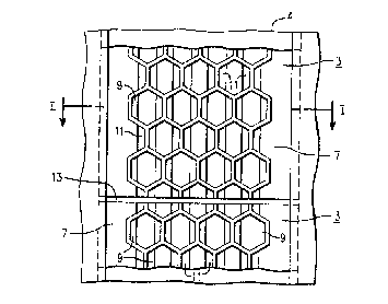
;Referring to Figures~l and`2~heréin,~ the`~
honeycomb l~abyrinth;seal 3 des~ribed~in the~
15 ~ aforementioned~U.~S~.~;pa~ent;~is~fo ~ ~from~-à~
p1ura1i~y~of~arcuate~se ~ ènts~each~comp~lsing~à ase~
portion~7 and~a~plurality of rows~of;honeycomb~cells~
9~extending rad1alIy~inwardly from~;the~basè` ~ ion~
7~so that~èach cell 9 is~open~`adjacent~thè~b~lades 1.
20 ~ -~A~plurality~of~pa~ssages~or~grooves~ are~so~
di~posed t at`each~ce1~1~;9~:is connected to-at~1east~
one~;passage~,;while~the~maj`or1ty o~the cells~are
connected~to;~two passages or~grooves~ The~groove~
on the 1eft side~of the~drawin~ is~open~to~the~
::: : ~: : : :

- 2 - 55,462
upstream steam while ~he groove 11 on the right side
of the drawing is open to the downstream and there
is an interconnection between the grooves ll and the
cells 9 allowing steam and water entràined in the
steam to flow across the base 7 of the seal from the
upstream to the downstream side of the~seal. The
cells 9~are generally hexagonal having~six~walls, a~
plurality of which are common with ad~acent cell
walls. '
An axially disposed gap 13~is~di~spoeed
between~the circumferentially adjacent honeycomb ;~
labyrinth seal segments which permits water
collected in the grooves ll to drain therefrom. An
appropriate drain, not shown, is also disposed in
the blade ring 5 to drain the water ~rom the seal
locating groove 4 in the blade ring 5.
Figure 3A;shows a typica 1 arrangement or
existing honeycomb seal designs in a steam turbine;~
blade path. A radla} step is~formed between~the~
seal inside diamèter and the outer~diameter;of the
downstream blade 16. ;~;A radi~al~ohannel~is~formed~
between surface 12 and sur~ac~e~l2A~for~`the~purpase~
of removing~steam~and moisture~rom~thé~blade'~path;~
flow. ~ It'~is~difficul~;to~achleve~;~e~icient~turning~
~ of the~flow~leaving the~rotating blade~ip~region~
under the'~sea~ ;and~thus~it~is~difficu1t'for~ the;~
moisture t'o~enter~;the~extraction~slot.~ This~ ,an~
lead~to disturbed~fIow conditions~Ln this~regL
It~is~postulated that moisture~drai~age'~
~ ~from~the~sea~ may follow~a;generally axial~path~and~
become entrained~into the~main do ~ stream~flow
' through stationary~blade 16, leadlng to lnoreased
.

2~3~9~
_ 3 _ 55,462
moisture erosion damage to the downstream rotating
blades.
By observing flow field behavior~and
moisture erosion characteristics downstream~of a
typical hon ycomb seal installation, it~has been
determined ~hat a disturbed flow pattern (standing
vortex) can exist in associatlon wltù the~radial
s~ep between the inne~ diameter of the seal~and the
outer diameter surface at the inlet to the~
downstream stationary blade row. Also, moisture
collected by ~the seal may not be flowing into the
downstream;moisture~removal or extraction~slot as
intended~. Both~of these phenomena~may be attributed
to a limited a~ility of the extra`ction steam and
water flow to negotiate the sharp 90~corner at the
seal exit edge. ~ ~ :
SUMMARY OF THE INVENTION
~ An object o~ the present invention is to ~;~
provide an improved honeyc~omb Iabyrinth~seal in
which the drainage path~for the moisture collected
~by the seal~direc;ts the~exit~water~f~low ~in~an~
outward radial dirèction~instead of~axial.
Another~ob~ect~of the~presént inYention ~is
to provide~an improved~honeyaomb~labyrinth~seal~in~
~ which the~centrifugal;a~fects~of the~rotating;~blade~
are utilized~to promote~an~outward~radial fIow~o~
both s~eam~and condensed~;watèr~from`the~ blade`~t1p
region near the~éX~t~edge.
Thes~e~and other objeats~of the~pr~sènt~
30~ ~ 1nvention~are~met by~provldin~ a~honeycom~ labyrlnth~
sea} cooperat1vely associated with rotatable~steam
turb1ne~blades~ànd 1nc1ud1ng ~;ba~e~gor~10n hav1ng

2 ~
4 ~ 55,462
an inlet edge and an outlet edge, ~ plurality of
rows of honeycomb cells extending radially inwardly
from the~base portion so that each cell is open
adjacent the blade, a plurality of~passages so
disposed that each cell is connected to`at:least one
passage:and at least one passa~e is open~upstream of
the rows of honeycomb cells and at least one passage:
is opened downstream of the rows of honeycomb cells,
thereby permitting steam to 10w through the ~
passages and cells from the upstream side~:to the
downstream side of the honeycomb labyrinth seal,
wherein a downstream most row of honeycomb~cells ;~
: extends beyond the exit edge of the backing plate,
and wherein an exit edge of the rotati~g blades ~ ~;
extends beyond the honeycomb labyrinth seal~
: These and other objects and àdvantages of
the honeycomb labyrinth seal of the present
invention will become more apparent with reference
to the following de~ailed descriptlon and;drawings. :~
20 ~ :BRIEF DESCR~PTION OF THE~DRAWINGS
Fig.~ l :is a:partial sectlonal view of a
known honeycomb labyrinth seal disposed in a~portion~
of a steàmed tùxbine ~takèn~along line~ I o~FLg.:2;~
Fig.: 2 1s a plan view taken from~the~
25; ~: dire~tion;~of~:line:II -~II
Fig. 3(a): is a~:partial cut away view~
showing the~honeycomb labyrinth::seal used~prior to ;;~
the~.present~ nv~ntion;~
Fig.~ 3(b:)~is~:a partial cut-away vièw~
~30 ~ ~showing the~honey~mb~labyrlnth~eeal~according~to a;~
preferred embodl~ent~o~:~the present~Lnvenelon;~
::
~:

t~
_ 5 _ 55,462
Fig. 4 is an enlarged top view o~ a
portion of the labyrinth seal of Fig. 3;
Fig. 5 is a cross-sectional view taken
along line IV of Fig. 4; and
Fig. 6 is a cross-sectional view taken
along line VI of Fig. 4.
.
DETAILED DESCRIPTION OF THE PREFERRED E~ODIMENTS
Referring to Figs. 3-6, the honey~omb
labyrinth seal 3 is connected ~o a seal support ring
12 by any conventional means through a ~ase portion
7. A moisture removal/extraction slo~ opening 14 is
formed between downstream stationary blade 16 and
the seal support ring 12 ad;acent the upstream
stationary blade 18. The rotating blade 1 ro~ates
lS in a direction perpendicular to the ~low direction~
The base portion 7 is provided with a
plurality of passages by grooves 11. The labyrinth
seal 3 is formed from a plurality of arcuate
segments each comprising a base portion 7 and a
plurality of rows of honeycomb cell~ 9 extending
radially inwardly from the base portion 7 so that
each cell 9 is open adjacent the blade 1. ~ach cell
9 is connected to at least one passage 11.
The base portion 7 has an exi~ side edge
20 which in the known seal described in Figs. 1 and
2 would have extended fur~her than the honeycomb
cells, so that the downstream-most row o~ honeycomb
cells would be centered over the downstream-most
groove 11, with the downstream-most side of those
3Q cells suppor~ed on the base portion 7.
:: ~

- 6 - 55,462
According to the present invention, the
downstream-most row 9A of honeycomb cells S is
centered over a strip 7A of the base portion at the
exit side ~the strip 7A having a width substantially
the same as the width of the grooves 11) so that a
portion of the cells in row ~A overhang the base
portion 7. The arrangement promotes an internal
moisture drainage path for those alternating groups
of cells having circum~erentially oriented cell wall
elements centered over the drainage grooves 11. The
exit drainage flow is thus directed in a radial
direction as it leaves the honeycomb cells at the
exit side. The radial drainage path is between the
exit edge 20 of the base portion 7 and the outermost
lS wall 22 of the cells 9 in row 9A. Moisture droplet
flow centrifuged outwardly from the rotating blade
tip and impinging on the open face of the honeycomb
cells 9 will promote a radially outward path for the
seal exit drain flow.
Fig. 6 illustrates the circumferential-
axial drainage path communication for all groups of
cells adjacent to those shown in Fig. 5.
Generally, the desired internal water
dxainage characteristics for the seal 3 are
determined by the inlet ~o exi~ pressure drop acxoss
the rotating blade row and the outward pressure
generated by moisture droplets leaving the blade tip
and entering the open face of the honeycomb cell
structure.
Preferably, the downstream-most or exi~
side row of honeycomb cells extends b~yond the exit :

3 ~
~ 7 ~ 55,462
edge 20 of the base portion 7 by about one half of a
groove width.
Referring to Fig. 3, it is noted that the
blade 1 preferably extends beyond the seal 3, rather
than being centered under the seal as in the known
seal of Figs. 1 and 2. Preferabl~, the amount of
extension is determined by-the tip section width,
with optimum overhang of the blade 1 baing
determined in relation to the width of throat
opening. The overhang of the rotating blade exit
edge promotes a seal exit drainage flow path in an
outward radial direction due to pressure from
centrifuged moisture droplet flow leaving the blade
tip. Also, the rotating blade exit edge overhang
also promotes radial expansion of steam flow
immediately downstream of the seal 3. This tends to
direct flow towards the moisture removal or
extraction slot 14 and provide well behaved (low
loss) flow conditions near the outer diameter
surface at the inlet to the downstream stationary
blade row.
The present invention allows for increased
width of downstream extraction or moisture removal
slots, or alternatively, allows reduced blade path
axial spacing if the extraction slot is a critical
restraint, due to upstream movement of the seal and
blade ring exit faces 20 and 12 ~Fig. 3) xelative to
the rotating blade.
Numerous modifications and adaptations of
the present invention will be apparent to those so
skilled in the art and thus, it is intended by the
following claims to covex all such modifications and
:

2~3~
- 8 - 55,462
adaptations which fall within the true spirit and
scope of the invention.

Representative Drawing
A single figure which represents the drawing illustrating the invention.
Administrative Status

2024-08-01:As part of the Next Generation Patents (NGP) transition, the Canadian Patents Database (CPD) now contains a more detailed Event History, which replicates the Event Log of our new back-office solution.

Please note that "Inactive:" events refers to events no longer in use in our new back-office solution.

For a clearer understanding of the status of the application/patent presented on this page, the site Disclaimer , as well as the definitions for Patent , Event History , Maintenance Fee  and Payment History  should be consulted.

Event History

Description Date
Inactive: IPC from MCD 2006-03-11
Application Not Reinstated by Deadline 2002-01-25
Time Limit for Reversal Expired 2002-01-25
Deemed Abandoned - Conditions for Grant Determined Not Compliant 2001-05-14
Deemed Abandoned - Failure to Respond to Maintenance Fee Notice 2001-01-25
Notice of Allowance is Issued 2000-11-14
Letter Sent 2000-11-14
Inactive: Approved for allowance (AFA) 2000-10-31
Letter Sent 1998-02-12
Inactive: Status info is complete as of Log entry date 1998-02-12
Inactive: Application prosecuted on TS as of Log entry date 1998-02-12
All Requirements for Examination Determined Compliant 1998-01-12
Request for Examination Requirements Determined Compliant 1998-01-12
Application Published (Open to Public Inspection) 1991-07-27

Abandonment History

Abandonment Date Reason Reinstatement Date
2001-05-14
2001-01-25

Maintenance Fee

The last payment was received on 1999-12-23

Note : If the full payment has not been received on or before the date indicated, a further fee may be required which may be one of the following

  • the reinstatement fee;
  • the late payment fee; or
  • additional fee to reverse deemed expiry.

Patent fees are adjusted on the 1st of January every year. The amounts above are the current amounts if received by December 31 of the current year.
Please refer to the CIPO Patent Fees web page to see all current fee amounts.

Fee History

Fee Type Anniversary Year Due Date Paid Date
MF (application, 7th anniv.) - standard 07 1998-01-26 1997-12-19
Request for examination - standard 1998-01-12
MF (application, 8th anniv.) - standard 08 1999-01-25 1999-01-04
MF (application, 9th anniv.) - standard 09 2000-01-25 1999-12-23
Owners on Record

Note: Records showing the ownership history in alphabetical order.

Current Owners on Record
WESTINGHOUSE ELECTRIC CORPORATION
Past Owners on Record
LEWIS GRAY
Past Owners that do not appear in the "Owners on Record" listing will appear in other documentation within the application.
Documents

To view selected files, please enter reCAPTCHA code :


To view images, click a link in the Document Description column. To download the documents, select one or more checkboxes in the first column and then click the "Download Selected in PDF format (Zip Archive)" or the "Download Selected as Single PDF" button.

List of published and non-published patent-specific documents on the CPD .

If you have any difficulty accessing content, you can call the Client Service Centre at 1-866-997-1936 or send them an e-mail at CIPO Client Service Centre.


Document
Description 
Date
(yyyy-mm-dd) 
Number of pages   Size of Image (KB) 
Abstract 1993-11-02 1 38
Claims 1993-11-02 3 113
Description 1993-11-02 8 467
Drawings 1993-11-02 3 74
Representative drawing 1999-08-17 1 19
Reminder - Request for Examination 1997-09-24 1 117
Acknowledgement of Request for Examination 1998-02-11 1 179
Commissioner's Notice - Application Found Allowable 2000-11-13 1 165
Courtesy - Abandonment Letter (Maintenance Fee) 2001-02-21 1 182
Courtesy - Abandonment Letter (NOA) 2001-07-22 1 171
Fees 1997-01-01 1 97
Fees 1996-01-01 1 92
Fees 1994-01-03 1 53
Fees 1994-12-20 1 68
Fees 1992-12-20 1 48