Note: Descriptions are shown in the official language in which they were submitted.
BACKGROUND OF THE INVENTION
Field of the_Invention
The present invention relates to a means and methods for
elevating structures, and in particular, to poles anchored in the
ground for vertically elevating any type of member or members to
an extended distance.
A number of structures or things must be suspended from the
ground. Examples are light fixtures, sirens, antennas, wires,
and the like. Many times these structures need to be rigidly
supported. Of course, a conventional means to accomplish this is
to utilize an elongated pole.
Commonly known examples of poles of this type are telephone
poles, electrical wire poles, light poles, sign poles, and
utility poles. Most of these types of poles are anchored in the
ground and extend vertically upward to many times tens of feet in
height. _
The widespread utilization of these types of poles is
indicative of the preference to utilize elongated structures or
poles to elevate objects in the air. For whatever reasons,
whether it be economical or practical, the demand for the poles
is very high for a number of different uses.
Poles of this nature can be made of a number of materials
and can be erected and installed in a number of ways. While each
of the commonly used poles achieves the end result of elevating
objects in the air, the different types commonly used have both
their advantages and disadvantages.
Wood poles represent the longest used and still today the
many times preferred type of pole. They are relatively
inexpensive, have a good height to diameter strength ratio, and
can be rather easily adapted for a number of uses.
Problems and disadvantages of wood poles, however, are at
least:
a. Difficult to find straight wood poles, especially for
taller heights;
b. Natural processes decay or at least weaken wood;
c. Wood is fairly heavy;
- 2 -
d. Pole comes in single long length which can be difficult
to transport;
e. Environmental problems associated with using trees
could effect availability;
f. Appearance;
g. Uncertainty of strength; and
h. Bottom end is buried in the ground and therefore even
more susceptible to decay and deterioration.
Wood, therefore, may represent a cheaper, more available
source for at least shorter poles, but is not the preferred type
of pole because of, in significant part, some of the above
mentioned problems.
An alternative pole that has more recently been utilized is
one made substantially of concrete. For even significantly tall
poles, concrete has great strength in compression and with a
steel cable infra structure offers strength in tension. With
advances in the nature of concrete, such poles offer a relatively
economical and very strong alternative to wood.
Disadvantages of concrete are at least the following,
however:
a. Very heavy, even with a hollow core (may not be able to
make very long);
b. Require a big crane or other power means to lift them;
c. The weight tends to cause them to shift when positioned
in the ground;
d. It is somewhat difficult to form holes or otherwise
attach structures to such poles; and
e. Such poles present shipping problems due to weight,
length, and width.
Again, while concrete poles do provide some advantages,
their disadvantages prevent them from being the preferred used
type of pole.
These types of above-mentioned deficiencies have resulted in
the pole of preference being comprised of a steel pole which is
anchored in the ground usually to poured concrete fill. Such a
combination allows the use of high strength yet lightweight
~o~~o~
hollow tube steel for the above ground portion, while utilizing
lower cost and high weight concrete as the anchor in the ground.
This also aids in installation as the concrete bases can be
poured and then the lightweight steel poles mounted thereon.
These advantages do not come without a price however. The
disadvantages of this type of pole axe at least the following:
a. Most expensive;
b. Concrete and re-bar (if used) must be custom designed;
c. Heavy, thick base plate must be welded to the
lightweight steel tube;
d. Galvanizing, which is the preferred protective coating,
is sensitive to the temperature differences between the
thick base and thin tube;
e. Concrete foundations must be accurately constructed on
the site according to the custom design;
f. The poles and the concrete fill, and any other hardware
many times are required to come from different sources
and therefore may not adequately match; and
g. Corrosion problems.
As can be appreciated, the problems with steel and concrete
foundation poles are not insignificant. Because the joint
between the steel and concrete will have to take much of the
stress provided by the long moment arm of the upwardly extending
pole, and because of wind load and other factors, it is critical
that for each installation the junction between the pole and the
foundation be accurately and correctly prepared. This is an
intricate matter requiring not only the correct design
specifications and construction of the concrete foundation and
the steel pole, but also accurate and faithful adherence to
design and installation specifications by field personnel in
forming the concrete foundation.
The custom design must include not only the height and
weight requirements associated with each particular pole, but
also must consider the type and strength of concrete used, the
design of the re-bar cage in the concrete, and the design and
placement of hardware attaching the steel pole to the concrete.
~~3~0~~.
As is well understood by those with ordinary skill in the
art, a custom design for the concrete foundations requires
significant expenditure of resources. Additionally, the success
of the design is then entirely dependent upon its implementation
in the field.
Unfortunately, a significant and real problem exists in
contractors carrying out the installations not doing so
accurately. Without a reliable match between the design
parameters of the concrete foundation and the parameters
associated with the steel pole with its actual installation, the
entire pole structure is susceptible to damage or failure.
Accordingly, substantial expense may be incurred over designing
and installing the concrete foundations to allow for field _
installation tolerances. Additionally, concrete requires up to
28 days to develop full strength needed for strength and to
_-anchor the bolts used to secure the pole.
A second major problem with steel pole and concrete
foundation combinations is that of corrosion. While presently
the corrosion problems are addressed by attempting to galvanize
all metal components, at least the following impediments exist to
that being successful.
The best environment far corrosion is generally within a few
feet above and below the ground line. Most concrete and steel
poles such as described above have the concrete bases foundations
poured and submerged from ground level down. Therefore, the most
corrosion-susceptible area of the metal, at or near the joint
with the concrete, is in that area where corrosion is the most
likely. Moisture in the form of standing water and condensation
is most concentrated in this area. Additionally, this is also an
area where the concentration of oxygen is high, which is one of
the components of corrosion and rust.
Secondly, as previously mentioned, the joint between the
steel pole and the concrete foundation often represents the
highest stress area for the combination. It is known in the art
that corrosion increases with stress.
_ 5 _
Third, the conventional way of securing the joint is to
utilize long bolts through a mounting plate of the steel pole
into the concrete. These bolts also take a majority of the
stress and are therefore very susceptible to corrosion.
Fourth, galvanizing simply cannot be very reliable for the
following reasons. Stress is detrimental to galvanization. An
annular base plate for the metal pole must be welded to the
tubular elongated portion of the pole. For galvanization to be
reliable, the surface must be extremely clean. Debris or dirt in
general, and in particular flux, which is hard to remove around
welded joints, will not take galvanization. Sometimes direct-
bury steel poles are utilized. Corrosion problems as well as
installation problems similar to described above exist.
Additionally, galvanization is accomplished by heating the
metal. For reliable galvanization, the metal must be heated
uniformly. However, the baseplate must be made of a much thicker
metal than the thin tubular pole on a practical commercial scale.
It is almost difficult during a reasonable production time to
have a thick-in-cross-section metal portion connected to a thin-
in-cross-section metal portion have the same temperature when
exposed to heat.
Additionally, the chemical nature of the steel or metal must
be known to obtain the correct galvanization result. Heat
differences can even crack the weld or otherwise damage the joint
or pole. The plate is generally made of a different metal than
the pole.
In short, the mounting plate and metal pole must be
galvanized inside and out to resist corrosion. For at least the
above reasons, it is very difficult to get such a combination
correctly galvanized. At a minimum, it is very expensive to do
it right. Then, even once galvanized, the high stress in the
area is damaging to the galvanization. Another risk is to
cracking of the weld because of different thickness of metal.
It can therefore be seen that the conventional types of
poles simply have significant and real problems which are
detrimental or are disadvantageous. There is a real need in the
art for a pole system which does not have these problems.
- 6 -
~~13~~~.~~
Additional problems with regard to presently used poles are
also significant in the art. One very practical and real problem
is involved with the shipping of such poles. For many uses,
poles are needed of lengths of thirty, forty, and even up to over
100 feet. While some applications require many poles of similar
lengths, and therefore may be sent by rail shipment, where long
lengths can probably be accommodated, many applications fnr such
poles require only a relatively small number. To ship such a
number by rail is expensive, particularly when many of these
applications still require some other type of over-the-highway
transportation to the ultimate location.
Generally trucks have a maximum effective carrying length of
between 40 and 98 feet, at least, for semi-trailers. However,
the effective load carrying length generally is no longer than
around 48 feet. Therefore, it is simply not possible to ship
poles of much longer length than this via tractor trailer without
special and expensive permits.
While attempts have been made to produce concrete poles in
segments, this requires significant installation efforts and
joints would create risk and problems. Additionally, it must be
understood that wood and concrete poles, with their heavy weight,
present shipping problems. Even with shipment in tractor
trailers, there is a weight limit of approximately 45 thousand
pounds, even for the longest semi-trailers. This would limit the
number of such poles that could be transported in one truck as
some poles, such as concrete, can each weigh several thousand
pounds, and even around or over ten-thousand pounds.
Additionally, weight permits are required for increasingly heavy
loads. Thus, the closer you come to the maximum weight per
trailer and truck, the more costs are incurred in obtaining
permits and the like for such heavy loads. This is important
because optimally the goal would be to have one tractor trailer
carry all the poles and parts required for one installation.
Because of limit on truck length and load weight limits, concrete
and even wood poles have certain limitations.
2~~~Q~~
Still further, for steel poles which are installed with
conventional poured concrete foundations, it may be possible to
transport the poles in trucks, but a disadvantage is again the
requirement that the concrete foundations be created and
installed by a local contractor where, in most cases, quality
control is less reliable. In other words, the entire combination
(pole and foundation) cannot be manufactured and shipped as one
unitary shipment and much reliance on a successful installation
is with the installer at the site.
The above rather detailed discussion of conventional poles
is set forth to attempt to aid in an understanding of the many
factors which are involved in choosing a type of pole,
manufacturing it, installing it, and ultimately maintaining it
for an extended, economical, and effective useful life. There is
no presently satisfactory system which is adaptable to virtually
every situation, is flexible in that it can be anchored in all
sorts of locations and ground types and all sorts of weather
environments, and is useful for all sorts of heights, wind loads,
and types of structures to be elevated.
Still further, for purposes of economy, there is a real need
for a pole system which can be easily shipped, whether only a few
or quite a few; is easy in terms of labor and resources to
install; and which can be maintained over a long life span.
Finally, there is a real need for an efficient pole system
which allows easy installation and shipment of the entire system
together, along with the structure or structures to be elevated
and any attendant hardware, such as wiring and the like.
It is therefore a principle object of the present invention
to provide a means and method for rigidly elevating a structure
which improves over or solves the deficiencies and problems in
the art.
Another object of the present invention is to provide a
means and method as above described which is generally universal
in its application for elevating different structures to
different heights for different situations, and with respect to
different installations of the base in the ground.
g _
A still further object of the present invention is to
provide a means and method as above described which is economical
in terms of the manufacture, materials, transportation,
installation, labor, and life span.
Another object of the present invention is to provide a
means and method as above described which is easy to assemble,
install, and maintain.
A still further object of the present invention is to
provide a means and method as above described which is durable
and strong, both in its individual components and campositely.
Another object of the present invention is to provide a
means and method as above described which permits pre-
installation design and concurrent shipment of all or most
components for each installation.
A further object of the present invention is to provide a
means and method as above described which improves corrosion
resistance.
Another object of the present invention is to provide a
means and method as above described which is an improvement with
respect to the problems caused by stress.
These and other objects, features, and advantages of the
present invention will become more apparent with reference to the
accompanying specification and claims.
SUMMARY OF THE INVENTION
The present invention relates to means and methods for an
improved pole system for rigidly elevating an object or structure
in the air with a base anchored in the ground. The invention
specifically solves or improves over many of the deficiencies in
the prior art by utilizing a special concrete base which is
anchored in the ground but to which a lightweight, strong steel
pole section or sections can be easily yet reliably secured.
The base includes an upper portion which extends above the
ground. The pole has a mating interior bore at its lower end
which slip fits over the upper section of the base, but does not
get nearer than a few feet from the ground. The upper portion of
_ g _
the base and the interior bore of the pole can either both be
tapered in a manner that the pole can be slip fitted a
predetermined distance onto the tapered part of the base and
secured there, or if the parts are not tapered, have a stop
member control how far the pole fits over the base.
Optionally, the pole can be comprised of a plurality of
steel sections, each added to the top of the preceding section in
turn beginning with the steel section attached to the base in a
similar manner by slip fitting each section to the other.
The system therefore provides a strong, almost unitary pole
structure which can be adapted to virtually any situation or
location. The strength of the base can be designed to
accommodate various pole heights and various ground conditions by
altering the make-up of the concrete of the base and any
reinforcing structure, as to the width of the base, and the
length of the base and other factors. Also, predefined simple
methods of field modifications can be made. In all instances,
any metal portions of the pole are kept out of the high corrosion
zone near the ground level. Yet, the above ground portion of the
system is almost fully comprised of the light weight, yet strong
steel. In turn, the base is made of the relatively heavy, stable
concrete which cannot corrode.
The invention also relates to the ability of the system to
be easily adapted, assembled, and installed. The invention
advantageously overcomes the problems associated with
installation such as reducing labor costs, material costs, and
design costs. It also provides ways to insure installation is
reliable such as providing for ways to plumb the base and/or pole
segments to insure that they are generally vertical during and
after installation.
Still further, the invention overcomes the severe problem in
the art of not being able to easily custom design the system of
pole structures for each installation and then easily ship,
install and maintain those poles.
- 10 -
~~3~~? ~~.
BRIEF DESCRIPTION OF THE DRAWINGS
Figure 1 is a front partial sectional view of a prior art
wooden pole set into the ground.
Figure 2 is a similar front elevational view of a prior art
substantially concrete pole set into the ground.
Figure 3 is a similar front elevational view of a steel pole
with a poured concrete foundation in the ground as known in the
prior art.
Figure 4 is a perspective view of the foundation and lower
portion of the steel and concrete pole combination of prior art
Figure 3.
Figure 5 is a sectional view taken along line 5-5 of Figure
4.
Figure 6 is a front elevational view with a partial
sectional view around the base of one embodiment of the
invention. _ _
Figure 7 is a similar view to Figure 6 showing an
alternative embodiment of the present invention.
Figure 8 is a view similar to Figure 6 showing one method of
installation of the metal pole section to the concrete base
according to the present invention.
Figure 9 is an enlarged front elevational view of one
embodiment of the concrete base for the present invention.
Figure 10 is a partial still further enlarged view of an
upper tapered section of the concrete base and the lower tapered
portion of the steel pole section according to one embodiment of
the present invention illustrating how these two elements are
slip fitted together and ultimately locked together.
Figure 11 is a front elevational view of a tapered concrete
base and tapered lower part of the pole section according to the
present invention, showing the use of a coating to assist in
installation of the system.
Figure 12 is a front elevational view of a base member
according to the present invention positioned in an excavated
hole for anchoring in the ground, further showing a leveling or
plumb means used to insure the base is plumb or vertical during
installation.
- 11 -
2~~~~~.G
Figure 13 is a front elevational view similar to Figure 12
showing an alternative combination for leveling or plumbing the
base member.
Figure 14 is a sectional view taken along line 14-14 of
Figure 13, but including an additional cross bar through the base
member and two additional leveling jacks from that illustrated in
Figure 13.
Figure 15 is a perspective view of a leveling jack depicted
in Figures 13 and 14.
Figure 16 is a perspective view of an alternative embodiment
for a leveling jack.
Figure l7.is a sectional elevational view of a base member
according to the present invention illustrating a means for
lifting and positioning the base member within an excavated hole
in a generally plumb position.
Figure 18 is a partial perspective view of the base member
according to the present invention showing means for a forklift
to lift and position a base means in an excavated hole in a
basically plumb position.
Figure 19 is a partial perspective view of a still further
embodiment for leveling and plumbing a base member in an
excavated hole.
Figure 20 is sectional view taken along line 20-20 of Figure
19.
Figure 21 is a still further alternative embodiment for a
leveling or plumb means for the present invention.
Figures 22 and 23 are side views depicting a method for pre-
assembling and installing a pole system according to the present
invention.
Figures 24A, 24B, 24C, and 24D are cross sectional view of
alternative pole structures that can be utilized according to the
present invention.
Figure 25 is a depiction of an alternative embodiment of the
present invention where the base member and the pole section do
not have matching tapered portions, but slip fit together until
abutting a stop member.
- 12 -
~fl~~01~
DETAILED DESCRIPTION OF THE PREFERRED EMBODIMENT
The detailed description of the preferred embodiments of the
present invention will now be set forth. It is to be understood
that this detailed description is intended to aid in an
understanding of the invention by discussing specific forms the
invention can take. It does not, nor is it intended to,
specifically limit the invention in its broad form.
This detailed description will be made with specific
reference to the drawings comprised of Figures 1 through 25.
Reference numerals are used to indicate specific parts or
locations in the drawings. The same reference numerals will be
used for the same parts or locations throughout the drawings
unless otherwise indicated.
The broad invention has generally been described in the
Summary of the Inventian. It is to be understood that in the
following description of specific preferred embodiments, the
structure elevated by the poles will be light fixtures or arrays
of light fixtures, such as are commonly used for lighting
sporting fields such as softball fields, tennis courts, and the
like. An example of one type of such arrays and fixtures can be
found at commonly owned U.S. Patent No. 4,190,881 by Drost and
Gordin issued 2/26/80. As will be further understood, the
present invention and all its preferred embodiments achieves at
least all of the stated objectives of the invention. It provides
a pole system which can be predesigned for specific applications.
As will be understood further, the preferred embodiments of the
invention will show how the system of the invention can be
predesigned for a particular application and location.
Furthermore, the invention is basically universal in that it can
accommodate almost all combinations of height, weight, location,
ground condition, shipping requirements, and installation
problems. It can also maintain the critically important
alignment both vertically and rotationally.
The invention accomplishes all of its objectives
economically and by providing a strong, reliable, long lasting
pole and base.
- 13 -
~~~~0~.~
To emphasize the advantages of the invention, the
description will first again briefly review some of the prof.lems
and deficiencies of commonly utilized prior art poles. The
advantages of the present invention will then be briefly
discussed with particular reference to use as light poles, and
then the specifics of the invention as applied to light poles
will be set forth.
Figure 1 shows a wooden light pole 10 having an upper
section 12 and a lower section 14. An array of light fixtures 18
includes three cross arms 20, each carrying a plurality of light
units 22 and is attached to upper section 12 of pole 10 by means
known in the art (not shown).
Pole 10 is installed in ground or soil 24 in an excavation
hole 26. As is commonly done in the art, the space around pole
in hole 26 is filled with a filler material to attempt to
better anchor pol-e--10 in the soil 24. Examples of material 28
are soil, tamped rock, or poured concrete, such as is known in
the art. Concrete has the advantage that it does not depend as
heavily upon the skill of the contractor for a reliable
foundation. Tamping rock properly in a deep hole is difficult
and time-consuming.
The problems with wood poles have been previously
discussed. Briefly, they are fairly heavy, are susceptible to
rot and decay, and it is difficult to find tall and straight
poles. Twisting and warping can also cause problems, such as
misalignment of the structure held by the pole, for example;
light fixtures. Perhaps more significantly, the installation of
the lower section 14 into ground 24 requires an exact and well
executed process to make sure the pole is vertical or plumb, and
that it will stay that way. Transportation of long poles is also
a problem.
As can be well appreciated by those of ordinary skill in the
art, sometimes poles are simply inserted into hole 26, which is
then backfilled with the removed soil. Soil simply does not have
the density or properties to reliably hold the pole in aligned
position either from axial, twisting (rotational), or lateral
- 14 -
movement over time. By adding material 28, the effective area of
the portion of pole 10 in ground 24 is increased, and the
properties of the material are such as to improve stability.
This process still relies significantly on the type of
installation job done by the installers. It can be seen that the
wood is exposed at ground level to moisture as is previously
described.
It is also to be understood that if crushed rock is used as
material 28 when installing any type of pole, it is crucial that
it be tamped accurately or the pole will lean. This requires the
rental or use of pneumatic tamper machine and knowledge of how to
accurately perform the tamping. This is a time-consuming task.
Figure 2 similarly shows concrete light pole 30 having a
lower end 32 anchored in ground 24 surrounded by material 28 like
the embodiment of Figure 1. Additionally, in this prior art
embodiment, a steel top section 34 is fitted over top end 36 of
pole 30 and array 18 of lights is in turn connected to top
section 34.
The problems with concrete poles have been previously
discussed. Although corrosion around ground level is not a
problem because of the use of concrete, the extreme weight of
such a mass many times causes pole 30 to sink into the soil or
otherwise tilt or laterally move. Similar problems in
installation for concrete poles exist as with pole 10 of Figure
1. Transportation of long poles because of length and weight is
also a problem.
Therefore, Figure 3 depicts the prior art light pole of
preference, namely steel light pole 40 which is connected to
bolts 46 (see figure 5), which are secured in material 28, which
is generally concrete. Array 18 of lights is secured by means
known within the art to the top of steel light pole 40, whereas
the bottom of pole 40 has an annular flange 44 surrounding
tubular pole 40 which is welded to pole 40 and secured by bolts
to material 28. Material 28 is poured concrete with a re-bar
design that must be installed on-site and is used to fill
excavated hole 26. It can be seen, however, that flange 44 is
within the high corrosion area near the ground.
- 15 -
Additionally, such as is known in the art, the joint created
at flange 44 bears a high amount of stress for the entire
combination. It therefore presents an unreliability factor in
the sense of concentrating a significant amount of stress in one
location. This is particularly true when referring to the
potential corrosion problems created by the joint. It must be
additionally understood that many times moisture accumulates
within the interior of these hollow poles and corroded material
and moisture can fall through the pole to the area around flange
44. This adds to the possible corrosion. Corrosion is virtually
as big a problem inside-out as it is from the outside-in for
these types of poles.
Even though the pole of Figure 3 is the most expensive, for
reasons previously described, it is also the most preferred
because it is lightweight, strong, aesthically pleasing, and its
installation is relatively easy when compared to a preferred
ground concrete fill (figure 3) or properly tamped rock backfill,
and when compared to installations such as is shown in Figures 1
and 2 which require a large crane to handle the higher weight of
the wood or particularly the concrete poles. Additionally, if
material 28 is cement, for optimum results, the crane must
continue to hold the poles until the concrete is basically set.
This requires time and money to rent the crane for that period,
and hire the labor for that period, as opposed to pole 40 of
Figure 3 where the concrete fill 28 can be set (requires up to 28
days to set up) and then the pole 40 afterwise installed. It is
to be understood that the setup time for concrete is generally in
terms of hours. Concrete truck cannot wait hours at a time.
Therefore, it requires generally a truck trip per pole which can
be very expensive. Also, unless multiple cranes are available,
only one pole can be installed over a period of hours.
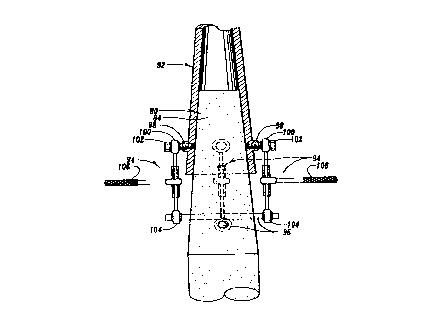
Figures 4 and 5 show in more detail the specifics of pole
and poured foundation 28 and 42 of Figure 3. In Figure 4, it can
be seen that flange 44 is attached to fill material 28 by the use
of long bolts 46 which extend deep into the material 28 and are
set there when the concrete is formed. Additionally, lines 48
- is -
represent generally the re-bar or reinforcing bars that need to
be designed into material 28 for each specific application.
Because bolts 46 extend deep into material 28, a significant
amount of stress of the whole system must be borne by material 28
so that bolts 46 will not pull out. Thus, the special and
specific designing of each foundation 28 for each application
(pole height, weight, wind load, etc.) must be accurately
predicted and implemented into the foundation 28 for it to be
successful.
Figure 5 depicts bolts 46 and also shows how flange 44
receives a portion of the bottom of the pole 40 in circular
aperture 50 that is completely through flange 44. Many times an
angled or beveled edge 52 is machined into flange 44 at the upper
junction between material 2B and pole 40 to allow for weld 54.
Figure 5 shows how thicknesses of flange 44 and pole 40 vary, how
it would be crucial for weld 54 to be done accurately, and how
the various problems with corrosion and galvanization can occur
as previously described. It is to be understood that many times,
to get a strong enough junction weld 54 must be a "triple weld"
which refers to multiple layers of welds around pole 40 in the
groove formed by beveled edge 52. The expense for this is
substantial as well as the reliance on the effectiveness of the
welds. It complicates the galvanization because of significant
heat and residue flux. It is to be understood that welds could
also be placed inside aperture 50 at the bottom of pole 40.
Figure 5 also shows that conventionally, nuts 53 are first
threaded onto bolts 46. Base plate 44 is then inserted onto the
bolts and rests on nuts 53. Nuts 55 then secured plate 44 to
bolts 46. Grout 56 is used to attempt to seal between plate 44
and foundation 28. The stress on the joint can therefore be
seen. Also, sometimes conduit or wiring 59 must be run through
grout 56 into pole 40. As can be appreciated, water (represented
by line 58) can accumulate or stand exactly around this joint,
both outside and inside the pole, whether from rain,
condensation, or other causes. The grout, manner junctions
between parts, and openings presents a risky corrosion
environment right at or near ground level.
- 17 -
Therefore, the preferred embodiments of the present
invention illustrate how many of these problems in the prior art
are overcome. The following will be a brief description of the
elements for preferred embodiments of the present invention.
Discussion of how the system of the invention allows for easy
design, manufacturing, installation, and maintenance will follow
that.
Figure 6 shows one preferred embodiment of the invention. A
pre-cast, pre-stressed concrete base 60 has a lower section 62
which can be anchored in ground 24. It is generally preferred to
anchor base 60 in material 28 which is poured concrete. An upper
section 64 (see Figure 8) of base 60 is tapered inwardly and
upwardly. It is to be understood that the tapered upper section
64 is above ground level of ground 24 and preferably generally
two or so feet above ground 24. It should also be understood
that upper section 64 does not need to be tapered as will be
later discussed.
The invention allows a pole to be comprised of either one
steel section, or several relatively short, lightweight, and
convenient-to-assemble sections. With respect to a pole holding
an array of lights for an athletic field, this allows:
1. Ease of separately establishing a pre-manufactured
concrete base rigidly fixed in the earth;
2. Advantage of a lightweight but strong top section
pre-assembled with a pre-aimed array of fixtures
which must accurately point to the field; and
3. Easy attachment of the pole to the base with
universal orientation of lights to the field.
In the embodiment of Figure 6, a pole section 66 is slip
fitted onto tapered upper section 64 (see figure 8) of base 60.
Pole section 66 itself is tapered along its entire length from
its lower end 68 to its upper end 70 to which is attached light
array 18. It is to be understood that the inside diameter of
lower end 68 of pole section 66 equal to or is just slightly
larger than upper section 64 of base 60 when it is slip fitted
down onto upper section 64. However, because of the relative
- 18 -
~~~~0~ ~
tapers, the farther pole section 66 is brought down upon upper
section 64 of base 60, the tighter the two components become
locked. Therefore, by utilizing sufficient force, the base 60
and pole section 66 can virtually become locked together without
additional hardware.
This means that the outside diameter of lower section 62 of
base 60 is greater than the inside diameter of part of pole
section 66. It is again to be understood that the invention also
contemplates use with bases and pole sections which are not
tapered.
In figure 6, pole section 66 could be about 40 feet in
length with a bottom inside diameter of around 9 1/2 inches, and
can utilize a 0.07 inch per foot taper uniform around the pole's
circumference (as measured along a side of the pole section 66).
Base 60 has a similar 0.07 inch per foot tapered top section 64
approximately 6 feet long with an overall length of close to 15
feet. The outside diameter of lower section 62 of base 60 is
also around 9 1/2 inches.
Figure 7 shows an alternative embodiment for the invention.
Instead of just one pole section 66, a lower pole section 72 is
slip fitted onto base 74 and an upper pole section 76 having the
same taper from top to bottom as section 72 is slip fitted onto
the top of lower pole section 72. It can be locked into position
in the same manner as previously described. It can therefore be
seen that a plurality of pole sections can be added to base 60 to
achieve required height for a structure. It is to be understood
that the Width and length of base 60 or 74 is designed for
overall height, weight, and load carrying ability for each pole
structure. Generally, the width and height of base 74 would be
greater than that for base 60 under fairly similar conditions
because of the added height.
In figure 7, base 74 is around 20 feet long with a lower
section diameter of around 13 1/2 inches. Pole section 72 is 40
feet long, has a lower diameter of around 13 1/2 inches and is
slip fitted about 6 feet down on base 74 but not lower than about
2 feet above the ground. 12 feet of base 74 extends below ground
_ 19 -
n.
~~~~~.~.
therefore. Pole section 76 is around 30 feet long, has a lower
end diameter configured to allow it to slip fit approximately 2
feet over the top of pole section 74. Appropriate gauge steel is
selected for height and load, and the strength of base 74 is
computed for these parameters. Generally, most poles must be
made to withstand 80 mph wind with 1.3 gust factor which includes
consideration of fixtures attached at the top.
Figure 8 depicts one method by which pole section 66 of
Figure 6 could be slip fitted onto base 60. A crane or
extendable arm 78 grasping pole section 66 could maneuver it over
base 60 and then slide or slip fit it down into position. It is
to be understood that in the preferred embodiment, pole 66 is
first gently slip fit onto base 60. Because generally light -.
array 18 has been mounted, some rotational positioning of pole
section 66 may be necessary, so that array 18 is facing in the
correct direction. As one of the major advantages of the present
invention, even after this preliminary installation, the pole
section 66 can virtually be adjusted 360' around base 60.
Figure 9 shows in enlarged form a preferred embodiment of a
base BO according to the present invention. As can be seen,
lower section 82 can be generally cylindrical in nature. Upper
section 84 is basically frusto-conical and has a not very
pronounced taper. Base 80 is hollowed out by bore 86 extending
through it. Base 80 could be solid, however. It is particularly
pointed out that at the top of upper section 84, a bevel 88 is
introduced so that any moisture will run off bevel 88 down bore
86 away from the pole which will be slip fitted upon base 80.
Additionally, openings 90 communicate with bore B6 to provide
access fox cables, wiring, and the like into the interior of base
80 and through the upper open end of base 80 into the.interior of
any pole section. Figure 10 is a still further enlarged partial
view of base 80 and shows a pole section 92 at least partially
slip fitted onto upper section 84 of base 80. In order to pull
pole section 92 further down tapered upper section 84 of base 80,
and to more securely lock the pole and base together, one way to
accomplish the same is to utilize ratcheting turnbuckles 94 to
- 20 -
2~~~~.
exert force to pull pole section 92 downwardly. A bar 96 can be
inserted through a bore transversely through base 80. A nut 98
can be welded to one or more sides of pole section 92 and a bolt
100 can be threaded into nut 9B. Ends 102 and 104 of turnbuckle
94 can be secured to bar 96 and bolt 100 respectively. By
operation of handle 106, the turnbuckle 94 can cause downward
movement of ends 102 and 104 to provide the pulling force and
thus lock section 92 onto base 80.
It is to be understood that multiple ratcheting turnbuckles
94 (and nuts 98 and bars 104) could be utilized around the
perimeter, or one could be connected at various positions. For
example, this procedure could be used on opposite sides of pole
section 92. It is to be further understood that the somewhat
resilient nature of steel of pole 92 in the preferred embadiment
allows some slight spreading which contributes to the resilient
forces and frictional engagement of pole 92 to base 80.
Therefore, no other hardware is needed for a secure junction.
Figure 11, however, shows an alternative method for locking
pole section 92 to bass 80. Instead of requiring the use of
force to pull the two elements together, a substance 108 could be
coated over either the upper section 84 of base 80 or the
interior of the bottom inside of pole section 92, or both.
Substance 108 can be an adhesive which would first allow the
initial slip fitting of pole section 92 to base 80 to provide
abutment and then lock the two elements in place. The large
surface area between the pole section and base when slip-fitted
together allows for perhaps not quite as good adhesive to be used
to accomplish its purpose compared with a joint of smaller
abutting surface areas. It is to be understood that such a
configuration reduces or eliminates significant gaps, pockets, or
chambers at the joint. Additionally, the use of the substance
108 could completely fill any air gaps or spaces whatsoever and
virtually eliminate places for water or air to work at corrosion.
The ability of the semi-solid or initially liquid substance to be
directed to fill up all spaces allows this advantage.
- 21 -
~~~a~~_~~
It is to be further understood that substance 108 could have
other advantageous properties. For example, it could have
lubricating properties to facilitate easier slip fitting and 360'
rotation of pole section 92. It could also have sealant
properties to further resist moisture and corrosion. As an
alternative, substance 108 could have any one of the above
mentioned properties and be advantageously utilized with the
invention. It is preferred, however, that it have at least
adhesive properties. In the preferred embodiment, an epoxy
substance, such as is known in the art, could be used which would
bond to both steel and concrete. Alternatively, silastic
(silicone), or urethane could be utilized. In general, substance
108 is applied in between a 5 to 30 mil thick coating, and
generally more along the lines of a 10 mil thick coating.
This eliminates the need for jacking the two elements
together, such as was explained with respect to Figure 10,.which
in many applications requires up to 2000 lbs. of pressure on each
side and up to 6 to 8 inches of further movement between the
elements to get a secure locking fit.
It is also to be understood that to further prevent
corrosion possibilities, gaskets or sealants could be used to
completely seal or fill up any spaces whatsoever in base 80 or
between the pole and base.
It can therefore be seen that the present invention utilizes
a tapered end of the base and the tapered pole sections to allow
easy and economical creation of a pole structure. To aid in an
understanding of how the invention in a complicated and arduous
manner provides such an advantageous combination, a short
discussion of many of the factors involved in designing this
combination will be set forth.
47ith regard to pole section 92, the following types (by no
means an exhaustive list) of elements have to be considered:
1. Amount of taper.
2. Shape and diameter of pole.
3. Number of sections.
4. Number of connections.
- 22 -
~~3~~~.~~
5. Weight to atrength ratio.
6. Wind load.
7. Type of steel~gauge of steel~wall thickness.
8. Stress through pole.
9. Corrosion resistance.
10. Galvanization inside and out.
11. Rotational alignment ability.
12. Transportability (length, diameter, weight).
13. Electrical or other interior connections or pieces.
14. hength of slip fit.
15. Crane or other lifting means size and availability.
16. Cost of materials.
17. Industry standards.
18. Type of structure to be suspended.
19. Installation location variables.
It is to be understood that a similar_plurality of factors
must also be analyzed for the base 80 (further including
properties unique to concrete and its use as a support base in
the ground) and the composite combination of base 80 and pole 92,
as can be appreciated by those skilled in the art.
In the preferred embodiment, the taper of pole section 92 is
a 0.14 inch reduction in diameter for every foot upwardly (or in
other words, a small angular degree of fraction of degree inward
taper). A possible range of tapers would be from .12 through .16
plus or minus .020 inch taper per foot of length. This is the
equivalent of the previously mentioned 0.07 inch per foot taper.
The taper allows the stress experienced by the pole section
to be distributed over 100 of the pole, and not necessarily
concentrated in any certain areas.
While the shape of the preferred embodiment of the pole is
circular in cross section, other shapes are possible where poles
need not be rotated for precision alignment of fixtures after the
base is set (see figures 24A-24D). Base $0 has a similar or
exactly identical taper to pole 92. In the preferred embodiment,
the base is hollow to reduce weight and allow wiring, etc. to be
brought in from the ground into the pole, and is made even
- 23 -
lighter by utilizing pre-stressed concrete (more strength per
pound). Wound wire is used instead of re-bar. The wound wire
has a tensile strength of between 250 and 275 thousand psi
(pounds per square inch). The concrete base 80 is then
centrifugally cast to provide a high density outside layer which
is extremely strong and is more resistant to moisture
penetration.
The need for the tapered joint between base 80 and pole 92
to be precise is essential. The base 90 is therefore cast in a
steel die and spun for 20 minutes. It is then cured in steam for
one day. Afterwards, it sits for a substantial period until it
reaches its full strength.
By using this high strength concrete, the weight is reduced
but the strength is retained.
It is to be understood that base 80 can be made longer for
different soil condition_s_and can be made longer and wider for '
different heights and stress conditions for poles. Generally in
the preferred embodiment, upper section 84 of base 80 is
somewhere around 7 to 8 feet in length. Because of the long
overlap for the slip fit joint (generally the 7 to 8 feet for 7
to 8 feet upper section 84), this comprises a relatively low
stress joint because it involves substantial surface area contact
and overlap length between members. There are no welds, bolts,
or any other hardware in this joint area (which can weaken the
joint or present focused stress points). Additionally, it is
above the primary corrosion zone by remaining two or more feet
above the ground. Additionally, the thickness of pole section 92
is the sane throughout its length and therefore it is easier to
reliably galvanize the steel.
It is therefore crucial to understand that when designing
and manufacturing the components for the invention, a variety of
different design considerations are taken into effect. However,
the advantage of the present invention is that they can be
analyzed and contemplated during design and then pre-manufactured
to allow an entire unit (pole sections) and base) to be shipped
together (along with fixtures and arrays). Quality control over
all of the elements can be more easily accomplished.
- 24 -
~~3~~~.!~
The problems with shipping with prior art devices have been
previously discussed. As can be seen in these preferred
embodiments, the lower weight of the pre-stressed concrete base
80, the lower weight of the hollow pole section 90 and any
additional sections, as well as the ability to section the pale
(if needed) allows for better flexibility and more economical
shipping.
The additional advantages of the invention can be seen with
respect to installation on site.
It is to be understood that one way to assemble and install
a pole system according to the present invention would be to
preassemble base 80 and any pole sections 92 horizontally on the
ground or otherwise, and then utilize a crane or similar device
to pull the combination upright and insert it into the excavated
hole. Then dirt, rock, or concrete could be poured around base
80 to set the combination in place. Such a process is
schematically depicted at Figures 22 and 23. It is to be
understood that various disadvantages of this method have been
previously discussed. One advantage of the present invention,
however, is that a majority of the weight of the combination is
in base 80. Therefore, the crane or other device would be able
to grip the assembly at a lower point (i.e., towards the center
of gravity of the assembly). From a practical viewpoint, this
allows use of a smaller crane or other machine which
significantly reduces cost if the crane were rented or otherwise
leased.
Secondly, flexibility of the invention can be seen in that
the base 80 could first be anchored in the ground and made plumb,
and then the pole sections can be slip fitted into place in any
manner desired. This would be done, preferably, by setting the
base 80 in concrete to avoid the unreliable backfill of rock or
dirt. Generally, the pole sections would be pre-assembled and
then the entire structure would be slip fitted to base 80. This
produces a reliable, rigid installation and alignment.
A number of advantageous methods have been developed to
facilitate this type of installation. First, as shown in Figure
- 25 -
12, base 80 can be, by means known within the art, set within
excavated hole 26 so that it rests on the bottom of the hole. A
level means 110 comprised of an elongated linear level 112 (in
this case four feet long) with a transversely extending foot 114
can be utilized in the position shown in Figure 12 to level or
plumb base B0. Foot 114 would be of a transverse length
(approximately 1/4" for a 4 foot long level and a .14 inch taper
per diameter for every foot) so that knowing the taper of upper
section 84 of base 80, when placed against the taper in the
position shown in Figure 12, level 112 will read that base 80 is
vertical along its longitudinal axis only when level 112 is
vertical. In other words, the tangent of the angle 116 farmed
between level 112 and taperd side of upper section 84 would equal
the length of foot 114 divided by the length of level 112. Level
means 110 can be moved around the perimeter of upper section 84
to insure it is plumb in all directions. This leveling process
could take place as concrete or other fill is put into hole 26
and such sets up. Then the verticality of any pole sections 92
slip fitted onto base 80 is assured. It is also to be understood
that level 112 could be used with other installation methods.
Figure 13 shows an alternative method to level or plumb base
80 (especially when base 80 is not, or cannot be set on the
bottom of hole 26). It is to be understood that a slurry is
preferred to be used to keep base 80 plumb during pouring of the
concrete. A bar 120 inserted through a lateral bore 122 which is
generally perpendicular to the longitudinal axis through base 80
could be utilized to sit into V-brackets 124 of screw jacks 126
on opposite sides of base 80. In a pendulum like manner, base 80
could swing around bar 120 (the bottom of the base would not
touch the bottom of excavated hole 26) to find its plumb position
in that plane (a vertical plane through the longitudinal axis of
base 80 and extending generally perpendicular to a vertical plane
through bar 120). This allows for setting base 80 in holes
deeper than base 80 or holes with a soft bottom which would not
support base 80. Screw jacks 126 could then be adjusted and
utilized with a conventional level on bar 120 or with respect to
- 26 -
~~~~t~
base 80 to insure that base 80 is level in the plane through the
axis of bar 120 parallel to the page at Figure 13.
Alternatively, one side of bar 120 could be blocked to a certain
height and then one jack 126 could be used to level the other
side. Additionally, a re-bar cage could be added to base 80 and
extend to the bottom of hole 26, or more concrete could be added
to fill up hole 26 under base 80.
Figure 15 shows screw jack 126 in more detail. V-brackets
124 are rotatably mounted to screw rod 128. A nut 130 is rigidly
secured to bracket 124 and screw rod 128 which is threadably
mounted in nut 132 rigidly secured to base 134. By turning nut
132, screw rod 128 rotates and moves up and down in base 134.
Figure 16 shows an alternative jack means that could be used
in the embodiment of Figure 13. Bar 120 could have an aperture
136 extending therethrough. Instead of v-brackets 124, screw rod
128 could simply extend through aperture 136. This time, by
turning nut 130, bar 120 would be raised or lowered.
Figure 14 shows an alternative embodiment to Figure 13. To
prevent base 80 from moving in any direction in excavated hole
26, an additional bar 138 could be inserted through an
appropriate transverse bore 140 (close to but spaced from bore
122) through base 80 but in a perpendicular direction to bar 120.
As shown in Figure 14, additional screw jacks 126 would hold bar
138. All screw jacks 126 could be adjusted to level or plumb
base 80. By utilizing the two bars, however, base 80 would be
locked into position. Therefore, when pouring concrete or other
material into hole 26, could not be easily moved out of alignment
base 80.
The Figures 17 and 18 show two further methods for
installing base 80 into hole 26 in a plumb manner. Tn Figure 17,
an aperture 142 from the exterior of base 80 into bore 86 would
allow a strap 144 connected to a crane or other machine to be
inserted and threaded out aperture 142. A locking pin 146 could
be slipped through loop 148 in the end of strap 144 to hold strap
144 in the position shown in Figure 17. By virtue of suspending
base 80 in the manner shown in Figure 17, it would basically find
its plumb position when lowered into hole 26.
- 27 -
~p~~~~4
In Figure 18, a bar 150 is inserted transversely through
base 80. This would allow a forklift 152 to raise base 80 and
again it would act somewhat like a pendulum, at least in one
plane to find its basically plumb position. The forklift can be
maneuvered to keep base 80 plumb during backfill with concrete.
Once the concrete is poured to top of hole 26, the forklift can
be removed as concrete will support the weight of base 80 and
keep it level.
Figures 19-21 show two additional, more intricate methods
for plumbing base 80 in hole 26. In Figure 19, a long bar 154 is
inserted through an oversized bore 156 so that there is some play
if base 80 were tilted in a vertical plane through bar 154. A
short bar 158 is inserted in a bore 160 perpendicular to bore 156
but partially intersecting bore 156. As can be seen in Figure
20, bar 158 would rest upon bar 154. Essentially, the abutment
point 162 between bars 158 and 154 would be a small intersection
of two rounded surfaces. Thus, base 80 would be able to tilt by
the forces of gravity in virtually any direction. Abutment point
162 acts somewhat like a knife-edge balance point and allows base
80 to automatically plumb itself to the extent it is free to tilt
in the setup. Screw jacks 126 can be utilized to roughly plumb
base 80. A fluid slurry mix of concrete can be poured to allow
base 80 to remain plumb.
Figure 21 shows a modification of this self plumbing setup.
To avoid having two transverse bores through base 80, Figure 21
utilizes a large bore 164 in which a sleeve 168 is positioned. A
rounded raised member extends from the interior center of the
sleeve 168. Bar 154 and jacks 126 can then be configured as
shown so that bar 154 extends through sleeve 168. the abutment
point 172 between member 170 and bar 154 again acts as a knife-
edge balance point to allow base 80 to plumb itself.
After installation by any of the above methods, the
invention in its assembled form presents a pole having accurata
and reliable anchoring in the ground, has sufficient strength in
both the base and the pole sections, and is resistant to
corrosion in the base and in the pole sections. It provides the
- 28 -
preferred steel upwardly extending pole without the disadvantages
of conventional steel poles. The invention therefore provides a
long lasting durable pole, which impacts on the cost of such
poles over their life spans.
It will therefore be appreciated that the present invention
can take many forms and embodiments. The true essence and spirit
of this invention are defined in the appended claims, and it is
not intended that the embodiment of the invention presented
herein should limit the scope thereof.
A primary example of an alternative embodiment according to
the invention can be seen at figure 25. Embodiment 180 consists
of a base 182 and pole section 1B8 similar to those previously
described. However, base 182 has a straight (not tapered) top
section 184. A stop member 186 extends laterally from base 182.
Pole section 188 is also a straight-sided (not tapered) tube
pole. It can be slip fitted onto top portion 184 of base 182
until it abuts stop 186. Epoxy 190 can be coated on both the
exterior of base 182 and interior of pole 188 to assist in
bonding the two. Sealant can also be used. It can be seen that
pole 188 is again held above ground. This embodiment is
particularly useful for square or multi-sided poles, that do not
require or are not desired to be tapered.
It is also to be understood that the pole sections are
preferred to be made of steel but other materials are possible,
for example, aluminum.
As can be seen by referring to the prior art design in
figure 5, the presently claimed invention completely eliminates
all the problems associated with potential corrosion, stress, and
even vandalism of the nuts, bolts, joint, and overall structure
of that prior art embodiment, even though in the prior art design
of figure 5, concrete is utilized in the ground, the metal is
attempted to be galvanized, and grout or other sealant is
attempted to be placed around the base/pole joint.
- 29 -