Note: Descriptions are shown in the official language in which they were submitted.
0 SERVOVALVE ~PPA~ATUS FOR USE ~ FLVID S~STE~[S
BACRGROUND OF THE INV~NTION
This invention relates to valve apparatus and, more
specifically, to a novel servovalve apparatus for use in
~luid systems to selectively direct or "port" fluid
~low.
Fluid systems are frequently used in mechanical
devices as a means of controlling or positioning various
mechanical components. As used herein, the term "fluid"
is used generally to refer to any substance which is
capable of flowing under pressure through a conduit.
Thus, the term "fluid" encompasses both gasses and
liquids, and the general term "fluid systems" is
intended to include both pneumatic and hydraulic
systems.
A fluid system typically comprises a pump for
pressurizing the fluid which is then used to provide the
force necessary to position and/or control a desired
mechanical component. For example hydraulic systems are
often used to control shovels or scoops on heavy
construction machinery. Similarly, pneumatic systems
are frequently employed in the field of robotics to
; control the position and movement of a desired object,
; such as, for example, a robotic arm.
Appropriate fluid controlling valves are essential
for the proper operation of virtually all fluid systems.
~or example, a valve may be used to direct pressurized
fluid first to one side and then the other of a plunger
which is slidable positioned within an elongated
housing. The operation of the valve thus controls the
flow of pressurized fluid to each side of the plunger
and thereby the position of the plunger within the
housing.
Examples of some of the more commonly used valves
in fluid systems are poppet valves (which control fluid
flow by a "pinching" action) and spool valves (which
control fluid flow by selective alignment of fluid
channels in a spool with orifices in a sleeve in which
the spool is slidable disposed). Poppet valves are
generally not well suited for servovalve applications,
typically have a significant lag time in their
operation, and many times have leakage problems. Spool
valves require very tight tolerances to avoid lea~age
between the spool and sleeve thus making them expensive
to manufacture and maintain. Also, because of the tight
tolerances, significant frictional forces can be
generated causing wear in the valves.
A valve having somewhat more recent origin is the
jet pipe valve, often called a flow-dividing valve. A
jet pipe valve comprises a fluid pipe having a small
orifice on its downstream end. Fluid flows through the
pipe at a substantially constant rate, and the small
orifice produces a "jet" of fluid out of the end of the
pipe. The pipe is provided with a suitable actuator
device which selectively directs the fluid jet toward
one or more nearby fluid paths. By appropriately
positioning the fluid pipe, the ratio of fluid flowing
into the nearby fluid paths can be controlled.
Conventional jet pipe valves suffer from
significant fluid leakage and are quite inefficient in
their use of fluid power. The operation of jet pipe
valves is also somewhat unpredictable at high pressures
r~ 7 ~_
and high fluid flow rates. Consequently, prior art jet
pipe valves typically incorporate small orifices ~less
than .005") and operate at fluid flow rates on the order
of 0.1 gallons per minute. Conventional jet pipe valves
are also typically quite bulky. Due to the significant
tangential forces present in jet pipe valves, bulky
mechanical actuators are often used. Torsional springs
and other balancing mechanisms are also often employed
in jet pipe valves in an effort to improve valve
operation. Consequently, prior art jet pipe valves are
often very difficult to properly maintain and adjust
during use.
BRIEF SU~MARY AND O~ECT~ OF T~E INVE~TION
In view of the foregoing, it is a primary object of
the present invention to provide a servovalve apparatus
for use in fluid systems which is capable of providing
high power output and operating under high fluid flow
rates but which does not require the maintenance of
tight tolerances between the valve's component parts.
It is an additional object of the invention to
provide a substantially frictionless-operating
servovalve apparatus.
It is another object of the invention to provide a
servovalve apparatus in which fluid flow forces are
reduced.
It is also an object of the present invention to
provide an efficient servovalve apparatus for use in
fluid systems which is simple in construction and
inexpensive to manufacture and maintain.
It is a further object of the invention to provide
a servovalve apparatus for use in fluid systems which is
both lightweight and compact in size.
Consistent with the foregoing objects, the present
invention is directed to a novel servovalve apparatus
for use in fluid systems which comprises an elongate
flexible valve stem or element having a fixed end and a
free end which is moveable back and forth along a
,
generally arcuate path. Th~ servovalve apparatus also
includes fluid carrying structure for directing a fluid
stream toward the free end of the valve element.
receiving plate is provided to define a generally
arcuate surface area adjacent the arcuate path over
which the free end of the valve element moves. The
receiving plate has at least one fluid channel
kerminating at a location along the arcuate surface
area. A porting element is disposed on the ~ree end of
the valve element to guide or port the fluid stream into
the fluid channel when the free end is deflected or
moved to a certain position over the receiving plate.
Apparatus for selectively deflecting the free end of the
valve element to the said certain position (and out of
said certain position) is also provided.
The apparatus for selectively deflecting the free
end of the valve element could, in accordance with one
aspect of the invention, include an armature affixed to
the valve element near the free end thereof, a
conductive coil which surrounds at least a portion of
the valve element adjacent its free end, and a magnet
assembly disposed adjacent the armature on at least one
side thereof. A source of electrical current supplies
current to the conductive coil to magnetize the armature
and thus cause it to either be attracted toward or
repelled from the magnet assembly. In this manner, the
porting element may be selectively positioned over the
fluid channel in the receiving plate or moved away
therefrom.
These and other objects and features of the present
invention will become more fully apparent from the
following description and appended claims, taken in
conjunction with the accompanying drawings.
BRIEF DESCRIPTION OF T~E DRAWINGS
Fi~ure 1 is a perspective partially cutaway view of
one presently preferred embodiment of the servovalve
apparatus of the present invention.
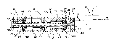
Figure 2 is vertical cross-sectional view o~ the
embodiment of Figure 1 taken along lines 2-2 of Figure
1 which also includes a schematic illustration of an
actuator device shown in broXen lines.
Figure 3 is a top, graphical view of the tip and
receiving plate configuration used with the apparatus of
Figures 1 and 2.
DETAI~ED DESCRIPTION OF THE PREFERRED EMBODINENT8
The presently preferred embodiments of the
invention will be best understood by reference to the
drawings, wherein like parts are designated with like
numerals throughout.
One presently preferred embodiment of the
servovalve apparatus of the present invention,
designated generally at 10, is illustrated in Figures 1
and 2. As shown, servovalve 10 comprises a body 20
which may be formed of any suitable material. It is
presently preferred that body 20 be formed of a soft
magnetic material which is easy to machine and which has
low hysteresis, such as, for example, silicon steel,
leaded steel, or low carbon steel.
While body 20 could have a wide variety of
different shapes and configurations, body 20 is
illustrated herein as being substantially cylindrical.
It is presently believed that the cylindrical
configuration of body 20 ~acilitates the manu~acture of
servovalve 10, and is readily susceptible of being
machined to accommodate the various component parts of
servovalve 10, a described further below.
The upstream end 29 of body 20 is provided with an
end plate 30, as illustrated in Figure 2. End plate 30
may be formed of any suitable material, such as, for
example, brass. End plate 30 is secured within the
upstream end 20 of body 20 in some suitable manner such
as by soldering or by means of an adhesive.
End plate 30 is provided with a nipple 32, as
shown, which may be attached to a source of pressurized
~3~
fluid using a c~nventional fluid tube (not shown). An
O-ring 33 preferably surrounds nipple 32 in a suitable
groove to assist in sealing nipple 32 to the fluid tube.
Opposite nipple 32, end plate 30 is provided with
5 a spindle 34. Spindle 34 and nipple 32 may
- advantageously be formed as an integral part of end
plate 30. Significantly, nipple 32, end plate 30, and
spindle 34 each have a bore therethrough which combine
to form a substantially uniform, longitudinal
passageway, the purpose of which will become more
readily apparent from the discussion which f~llows.
A mandrel 40 is pro~ided on spindle 34 of end plate
30. Mandrel 40 may be formed of any suitable material
such as, for example, steel, and could be formed as an
integral part of end plate 30 or as a separate element.
A downstream end disk 41 of the mandrel is made of a
non-magnetic matarial such as aluminum, plastic, etc.
The mandrel 40 will be further discussed hereafter.
A suitable electrical conductor is wound around
mandrel 40 so as to form a conductive coil. Any
suitable electrical conductor may be used, such as, for
example, # 30 copper magnet wire. The ends of wire 42
are then connected to suitable insulated wires 16 which
pass out of body 20 through a suitable opening in end
25 plate 30. As shown in Figure 1, wires 16 may be
provided with some type of connector plug 18 for
connecting wires 16 (and thus conductive coil 42) to a
suitable source of electric current.
As illustrated in Figure 2, a flexible conduit 60
passes through the central bore of end plate 30 and the
central bore of the mandrel 40. The upstream end 62 of
conduit 60 is secured within end plate 30 in some
appropriate manner, such as, for example, by means of a
conventional bushing 63. Conduit 60 may be formed of
any suitable material, such as, for example, steel.
An armature 64 is secured to conduit 60 so as to
lie adjacent mandrel 40. Armature 64 may, for example,
2 6~ r~ ~
be formed of steel and may be slidable secured on
conduit 40 by friction or a suitable adhesive.
Armature 64 may have virtually any suitable
geometric configuration. For example, armature 64 may
be a substantially rectangular member as best seen in
Figure 1. It is presently preferred that a portion of
armature 64 near mandrel 40 be diametrally enlarged, as
shown in ~igures 1 and 2. It is believed that the
diametrally enlarged portion of armature 64 will assist
the armature in conducting the magnetic induction
current necessary for the proper operation of servovalve
10, as described in more detail below.
Two magnets 72 and 73 are positioned on opposite
sides of armature 64, as shown in Figure 2. Magnets 72
and 73 may, for example, be secured to body 20 by means
of suitable magnet mounts 70. Significantly, one magnet
72 or 73 is configured and positioned such that it
presents a north magnetic pole facing armature 64, while
the other such magnet is configured and positioned so as
to present a south magnetic pole facing armature 64.
While magnets 72 and 73 could be formed of a wide
variety of different materials, it is presently
preferred that magnets 72 and 73 be formed of a rare
earth metal material. It~is believed that rare earth
magnets facilitate making servovalve 10 small and
lightweight due to their superior magnetic
characteristics.
The downstream end of conduit 60 is preferably
provided with a tip 66 which may be formed of any
suitable material, such as, for example, brass. Tip 66
is secured to conduit 60 in some suitable manner, such
as by means of friction or by means of a suitable
adhesive. Importantly, tip 66 is configured as a fluid
orifice or orifices through which fluid may flow from
conduit 60.
The downstream end of body 20 is provided with a
receiving plate 80 which may, for example, be formed of
F~ ~ '
brass. Receiving plate 80 is secured within body 20 in
some appropriate fashion, such as by means of solder or
adhesive.
Receiving plate 80 has one or more fluid channels
or groups of fluid channels 84 and 86 formed therein
which terminate in openings or groups of openings 85 and
87, respectively (see Figure 1). Channels 84 and 86
advantageously originate within and communicate with an
arcuate or concave socket 82 which is formed in the
surface of receiving plate 80 inside body 20.
Preferably, the radius of curvature of socket 82 is
substantially equal to the radius sf curvature of the
arcuate pathway over which the downstream end of conduit
60 moves during flexure, for reasons which will become
more fully apparent from the discussion which follows.
Figure 3 shows a top, graphical view of an
exemplary configuration for the receiving plate 80 and
tip 66. Here, the receiving plate 80 has two rows of
three channels (or more) 85 and 87, and the tip 66 has
one row of three channels or orifices 86 each positioned
midway between a corresponding pair of channels 85 and
87 when the tip is in the nondeflected position.
Although there will generally be some distance
between tip 66 and receiving plate 80, it is preferable
to minimize this distance in order to reduce the amount
of fluid leakage from between tip 66 and receiving plate
80. The distance between tip 66 and receiving plate 80
is not so small, however, that substantial frictional
forces between the tip 66 and receiving plate ~30 are
present or that a lubricating fluid must be used in
servovalve 10. Significantly, by providing receiving
plate 80 with a socket 82, as described abo~e, the
distance between tip 66 and receiving plate 80 can also
be maintained at a substantially constant minimal level
during flexure of conduit 60.
When used in a fluid system, servovalve lO is
attached by means of nipple 32 to a source of
7 ~
pressurized fluid. The pressurized fluid then enters
conduit 60 through nipple 32 and travels toward
receiving plate 80.
Conductive coil 42 is connected by means of wires
16 and plug 18 to a source of electricity. As
electrical current flows through coil 42, a magnetic
current is induced through the center of coil ~2 in
accordance with well-known principles of
electromagnetism. Because of this induced magnetic
current, armature 64 which is adjacent one end of coil
42 will be magnetized as either a north magnetic pole or
a south magnetic pull depending upon the direction of
the electrical current in coil 42. As a result,
armature 64 will be ~agnetically attracted toward either
magnet 72 or magnet 73, and conduit 60 will be deflected
either upwardly or downwardly in Figure 2.
For example, the direction of the electrical
current through coil 42 may cause armature 64 to be
magnetized as a north magnetic pole. Thus, if magnet 72
is positioned so as to present a north magnetic pole
facing armature 64 and magnet 73 is positioned so as to
present a south magnetic pole facing armature 64,
armature 64 will be magnetically repelled from magnet 72
and magnetically attracted toward magnet 73. As a
result, conduit 60 will be deflected downwardly in
Figure 2. Conduit 60 could, of course, also be
deflected upwardly in Figure 2 in a similar fashion by
simply reversing the direction of the electrical current
in coil ~2.
It will be readily appreciated that if conduit 60
is deflected upwardly in Figure 2, fluid will flow
through conduit 60 and through tip 66 into fluid
channels 84. On the other hand, if conduit 60 is
deflected downwardly in Figure 2, fluid will flow
through conduit 60 and through tip 66 into channels 86.
Thus, the flow of fluid into fluid channels 84 and 86
may be selectively controlled by simply controlling the
;7~ lg
direction of the electrical current in coil ~2 which
determines the direction conduit 60 is deflected.
Advantageously, as mentioned above, by providing
receiving plate 80 with a concave socket 82 which has a
radius of curvature substantially equal to the radius of
curvature of the pathway over which the downstream end
of conduit 60 moves, a relatively close tolerance can be
maintained between tip 66 and concave socXet 82. As a
result, the flow of fluid through conduit 60 can be
virtually stopped by positioning conduit 60 in the
nondeflected position, as illustrated in Figure 2, such
that the orifice formed by tip 66 lies between fluid
channels 84 and 86. While some fluid leakage can still
be expected, the fluid leakage will be minimal as
compared with prior art jet pipe valves. In fact, the
performance of servovalve 10 can approach that o~
conventional spool valves while being much less
expensive and much easier to manufacture and maintain.
As noted above, there will likely be at least some
~luid which leaks into the interior of body 20 from the
orifice formed by tip 66. Such fluid may occasionally
contain magnetized particles which could travel toward
magnets 72 and 73 and become affixed thereto. It will
be readily appreciated that such a condition could have
a significant adverse effect upon the performance of
servovalve 10.
In order to prevent magnetic particles from coming
into contact with magnets 72 and 73, an appropriate
filter may be provided around tip 66. For example, a
conventional porous metal material may be provided
around tip 66 to act as a filter for any magnetized
particles in the fluid. Alternatively, a series of
baffles 92 may be provided around tip 66, as shown in
Figure 2, and magnetic filters 93 may be positioned
therebetween. As magnetized particles travel between
baffles 92, magnetic filters 93 will trap such particles
and prevent them from coming into contact with magnets
~3~7~
11
72 and 73.
As shown schematically in Figure 2, servovalve 10
may be connected to a suitable actuator 12, if desired.
Thus, by directing fluid through channel 84 in receiving
plate 80, the pressurized fluid can be directed through
channel 14 so as to cause extension of piston rod 13 of
actuator 12. Fluid could thereafter be directed throu~h
channel 86 in receiving plate 80 to channel 15 which
would cause piston rod 13 to be retracted.
Advantageously, an actuator 12 may be connected
directly to servovalve 10 by means of a suitable sleeve
(not shown). In such case, in order to facilitate
sealing the sleeve around the downstream end 28 of body
20, an 0-ring 26 may be provided around body 20, as
shown.
From the above discussion, it will be appreciated
that the present invention provides a servovalve
apparatus which can readily be used with high fluid flow
rates and which can provide relatively high power output
but which does not require the very tight tolerances of
many prior art valve devices. It has, for example, been
found that the servovalve apparatus of the present
invention may easily be used with fluid flow rates
within the range of from approximately one gallon per
minute to approximately four gallons per minute. This
is 10 to 40 times greater than the fluid flow rates
typically used with conventional jet pipe valves.
The physical configuration of the servovalve
apparatus of the present invention also makes it
possible to construct the servovalve apparatus much
smaller than many conventional valves. The small size
and relatively light weight of the servovalve apparatus
is also achieved in part due to the use of rare earth
magnets within the servovalve apparatus.
The invention may be embodied in other specific
forms without departing from its spirit or essential
characteristics. The described embodiments are to be
~ 0 3 ~ ~3 ~
12
considered in all respects only as illustrative and not
restrictive. The scope of the invention is, therefore,
indicated by the appended claims, rather than by the
foregoing description. All changes which come within
the meaning and range of equivalency of the claims are
to be embraced within their scope.