Note: Descriptions are shown in the official language in which they were submitted.
~0~ i~.G:'~
BRAKE ACTUATOR WITH SLACK
ADJUSTER DISABLING MECHANISM
The present invention relates to brake actuators, and
particularly to such brake actuators as incorporate a
combined back-up emergency and parking brake in conjunction
with the primary service brake.
In one such brake actuator, the service brake is
air-applied, spring-released. and the emergency/parking
brake is spring-applied, air-released. A lost-motion
coupling between the service and emergency brake pistons
allows either one or both pistons to be effective to apply
braking force. By utilizing a common source of air for the
service and emergency brakes, failure of the service brake
due to loss of air, for any reason, such as insufficient
compressor capacity, automatically results in the emergency
brake being applied under spring force. Typically, force
amplification levers are employed to obtain high braking
force without increasing cylinder size. This, in turn,
requires the use of a slack adjuster to compensate for
excessive piston travel throughout the range of brake shoe
wear.
A typical slack adjuster used with the aforementioned
brake actuator employs a toothed ratchet wheel that is
arranged to effect rotation of an axially fixed nut member
having threaded engagement with a brake actuator rod that is
fixed against rotation. A pawl is actuated to engage a
tooth of the ratchet wheel when the piston stroke exceeds a
1
~035~69
nominal distance during a brake application. During a brake
release, a spring connected to the pawl pulls it in a
direction tangential to the circumference of the ratchet
wheel teeth to effect rotation of the ratchet wheel and,
consequently, of the nut member. Since the threaded
actuator rod is fixed against rotation, this rotation of the
nut member forces the actuator rod to advance axially and
thereby take up excess brake shoe clearance. The slack
adjuster is designed to operate in increments of one tooth
at a time. Since the maximum distance that the pawl shifts
is determined by the maximum piston stroke, the continuous
slack adjuster action will assure that the pawl does not
normally shift a distance greater than that necessary to
engage a single tooth at a time.
The aforementioned brake actuator is also provided with
a manual release mechanism for releasing the parking brake
when no air is available. This manual release mechanism
operates through the brake actuator rod assembly to shorten
the brake linkage which, in turn, causes the service and
emergency pistons to bottom out. Once this occurs,
continued operation of the manual release mechanism forces
the actuator rod assembly to retract the brake shoes. It
will be appreciated, however, that in bottoming out during
this manual release operation, the service and emergency
pistons move a distance sufficient to cause the slack
adjuster pawl to shift several teeth over the ratchet
wheel. This results in the line of action of the pawl
2
2U~5~69
swinging from its normal tangential alignment relative to
the ratchet wheel teeth to a generally radial alignment
relative to the ratchet wheel, thereby becoming jammed to
render the slack adjuster inoperable.
Moreover, the high compressive forces acting on the
brake linkage when the service and emergency brakes are
both applied, result in over-travel of the brake actuator
pistons due to slight bending of the linkage components,
thus giving a false indication of excessive brake shoe
wear. The piston over-travel resulting from this apparent
excessive brake shoe wear causes the slack adjuster to
over-extend the brake linkage in attempting to compensate
for slack that does not actually exist. Accordingly,
insufficient brake shoe clearance and possible brake
lock-up can occur.
SUMMARY OF THIE INVENTION
It is the object of the present invention to
automatically disable the slack adjuster under the
aforementioned conditions in which the slack adjuster
mechanism could either become jammed or could operate
inappropriately.
In carrying out the foregoing objective, there is
provided in a brake actuator device an actuator rod
assembly, a service brake, and an emergency/parking brake
for effecting axial operation of the actuator rod
assembly, a slack adjuster for varying the effective axial
length of the actuator rod assembly, a lost-motion
3
2035~G9
connection via which the service brake and
emergency/parking brake are connected such as to permit
actuation of the service brake independently of the
emergency/parking brake, and a mechanism for disabling the
slack adjuster whenever the emergency/parking brake is
operated.
These and other objects and advantages of the present
invention will appear in the following more detailed
explanation when taken with the accompanying drawings in
which:
FIG. 1 is a sectional assembly view of the force
actuator of the present invention;
FIG. 2 is a section view taken along the lines 2-2 of
FIG. 1;
FIG. 3 is a section view taken along the lines 3-3 of
FIG. 1; and
FIG. 4 is a partial section view of FIG. 2 showing the
slack adjuster disabling mechanism in its activated
position.
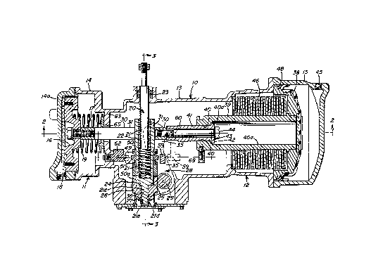
Referring to FIGS. 1 and 2, there is provided an
actuator device 10 including a service brake portion 11,
and an emergency/parking brake portion 12 in a housing
13. Service brake portion 11 comprises a service brake
cylinder 14 and emergency/parking brake portion 12
comprises an emergency/parking brake cylinder 15. A
4
203~~,(:;~
service brake piston 16 is reciprocally disposed in service
brake cylinder 14 and includes a push rod 17 that extends
toward emergency/parking brake portion 12. A port 18 is
provided in the service brake cylinder 14 via which fluid
pressure may be supplied to the pressure side of service
brake piston 16 and released therefrom. A return spring
19 acts on the opposite or non-pressure side of service
brake piston 16 to urge the piston into engagement with a
stop provided by the cylinder cover 14a.
An actuator rod assembly 20 is disposed in housing 13
between service brake cylinder 14 and emergency/parking
brake cylinder 15. As best seen in FIGS. 1 and 3, actuatcr
rod assembly 20 comprises a screw rod 21 on which an
internally-threaded hollow rod 22 is rotatably connected.
The non-threaded end of screw rod 21 projects externally of
the brake actuator housing 13 for connection with brake
apparatus, such as, a tread or disc brake, or the like (not
shown), guided by a spherical joint 23. A flanged end 24
of hollow rod 22, apart from its threaded connection with
screw rod 21, rests on a support base 25 of a socket member
26. Socket member 26 is formed on one arm 27 of a
bellcrank lever 28 that is pivotally connected to housing
13 by a trunnion 29.
The service piston push rod 17 is formed with a yoke 30
to provide an opening 31 through which the actuator rod
assembly 20 projects. Opening 31 is elongated in the
direction of operation of service brake piston 16 to
accommodate motion thereof. Yoke 30 is formed with
~O~S~6~
U-shaped openings 32 having rollers 33. Rollers 33
include outwardly-directed pins 34 to which the respective
arms 35 of bellcrank lever 28 are connected. As best seen
in FIG. 3, the other bellcrank lever arm 35 is bifurcated.
Socket member 26 is provided with a through opening 36
via which a shaft 21c of hollow rod 22 extends. The end
of shaft 21c is threaded to receive a nut 21d. Following
assembly on shaft 21c, nut 21d is locked against rotation
relative to shaft 21c by insertion of a pin 21e through
the nut and shaft. This provides a drive arrangement via
which the slack adjuster may be manually operated to let
out slack, such as to accommodate the replacement of brake
shoes.
Reciprocally disposed in emergency/parking brake
cylinder 15 is a piston 38 having a hollow push rod 39
that projects inwardly into housing 13 coaxial with
service brake piston 16. A guide bore 40 and counterbore
40a of push rod 39 receive an extension member 41 having a
flange 42 supported on a shoulder 43 between bores 40 and
40a. Extension member 41 abuts yoke 30 of service piston
push rod 17 to which it is fastened by a through bolt 44,
so as to become an integral part of service piston push
rod 17. A port 45 is provided in the emergency/parking
brake cylinder 15 via which fluid pressure may be supplied
to the face of piston 38 to urge the piston in a release
direction. Acting on the non-pressure side of
emergency/parking brake piston 38 is a spring pack 46
6
i
2035~G~~
comprising a plurality of stacked belleville-type spring
washers. These spring washers are normally maintained in
a compressed state, as shown, due to the fluid gressure
force acting on the face of the piston. The periphery of
emergency/parking brake piston 38 is fit with an annular
plastic guide ring 48 that is engageable with the wall of
emergency/parking brake cylinder 15 to thereby maintain
proper axial piston alignment. This alignment is
transferred to service brake piston 16 by reason of its
push rod connection with extension member 41, which is, in
turn, operable within guide bore 40 of the
emergency/parking brake piston push rod 39.
A slack adjuster bracket 49 is carried on hollow rod
22 of the actuator rod assembly 20 by a shoulder 50 at one
end and an annular rim 50a of socket 26. A ratchet wheel
51 is rotatably locked to hollow rod 22 by reason of a key
52 farmed on the ratchet wheel and a keyway 53 on hollow
rod 22. Pivotally-mounted to slack adjuster bracket 49 by
a pin 54 is a support lever 55 having a pawl 56 pivotally
suspended by a pin 57 at its free end. A pair of take-up
springs 58 are each connected at one end to slack adjuster
bracket 49 and at their other end to pawl 56, so as to
exert a force on pawl 56 in a direction generally tangent
to the circumference of the ratchet wheel teeth at the
point of engagement therewith. As best shown in FTG. 1,
there is connected to pawl 56 a trigger arm 59 having a
roller 60 spaced in proximity with yoke 30, so as to be
7
~03~~f;9
engaged by movement of service piston 16 after a
predetermined distance. A detent spring member 61 is
screwed to the slack adjuster mounting bracket for
engagement with ratchet wheel 51 to prevent inadvertent
rotation of the ratchet wheel due to vibration. An
anti-rotation element 62 is carried on a wall 63 that
serves as a spring seat for the service piston return
spring 19. Anti-rotation element 62 is disposed adjacent
the slack adjuster mechanism in a vertical channel 64
formed by the slack adjuster bracket 49 to thereby prevent
rotation of the slack adjuster bracket by take-up spring 58
when roller 60 is engaged by yoke 30 to trigger the slack
adjuster. Further provided on wall 63 is a guide plate 65
for maintaining proper axial alignment of service piston
16.
Connected to emergency/parking brake piston 38, via an
annular groove 66 that encircles the periphery of piston
push rod 39, is a slack adjuster disabling mechanism 67.
An actuating lever 68 of disabling mechanism 67 carries a
follower pin 69 at one end that rides in annular groove
66. A pin 70 pivotally connects actuating lever 68 at a
point intermediate its ends to a support bracket 71 on
which the disabling mechanism 67 is mounted. The support
bracket 71 is formed on the inside of a cover 72 that
closes an access opening 73 in housing 13. Another pin 74
pivotally mounts a vane 75 to support bracket 71 at a
location in which the vane 75 is capable of being rotated
8
2U3J~69
into and out of the line of motion of pawl 56, as shown in
FIGS. 2 and 4. A link 76 connects the free end of
actuating lever 68 to vane 75 such that axial movement of
the emergency/parking brake piston 38 effects the
aforementioned rotation of vane 75. The surface of vane 75
in the path of pawl 56 is arcuate, the center point of the
radius of this arcuate surface being congruent with the
axis of pivot pin 74, for a purpose hereinafter explained.
In the deactivated or released condition of the brake
actuator device 10, pneumatic pressure is absent from the
face of service brake piston 16, allowing return spring 19
to force service brake piston 16 leftwardly against its
stop on the cylinder cover 14a. At the same time,
pneumatic pressure is applied to the face of
emergency/parking brake piston 38 to force this piston
leftwardly, compressing its spring pack 46. When it is
desired to apply the brakes, pneumatic pressure is applied
to port 18 and the face of service brake piston 16, forcing
the piston rightwardly. This rightward movement of service
brake piston 16 is translated by bellcrank lever 28 into
movement of actuator rod assembly 20 in a direction
substantially perpendicular to the direction of movement of
the service brake piston 16. The relative length of the
bellcrank lever arms 27 and 35 provides the mechanical
advantage necessary to achieve the desired brake forces at
the output end of hollow rod 22. Spherical joint 23 allows
swivel movement of the hollow actuating rod assembly, due
9
2035~.6~
to the arcuate motion of the bellcrank lever arm 27, while
the U-shaped opening in yoke 30 for roller 33 is provided
to allow for displacement of the bellcrank lever arm 35
from axial alignment with service brake piston 16 due to
arcuate motion of bellcrank lever arm 35. The service
piston stroke takes place independently of
emergency/parking brake piston 38 due to the lost-motion
connection provided between flange 42 of extension member
41 and shoulder 43 in the emergency/parking brake piston
push rod 39.
In the event the piston stroke becomes excessive due,
for example, to brake shoe wear, yoke 30 engages roller 60
of trigger arm 59 to activate the slack adjuster device.
When this occurs, pivot lever 55 is rotated about pivot pin
54 in a counterclockwise direction, as viewed in FIG. 2,
thereby pulling pawl 56 rightwardly against the resistance
of spring 58 to permit the end of the pawl to engage a
tooth of the ratchet wheel. A subsequent release of
pneumatic pressure from the face of service brake piston 16
to effect a release of the service brake application allows
return spring 19 to farce service brake piston 16
leftwardly to its release position. As this occurs, yoke
30 is disengaged from roller 60 of trigger arm 59 and the
take-up springs 58 are effective to pull pawl 56 in a
leftward direction, whereby ratchet wheel 51 is caused to
rotate in a clockwise direction, turning hollow rod 22 with
it. In that screw rod 21 is rotatably fixed relative to
hollow rod 22, by reason of its connection with the
~U35~6'~
appropriate tread or disc brake apparatus (not shown), the
screw rod 21 is forced to move axially with rotation of the
hollow rod 22, thereby increasing the length of the actuator
rod assembly 20. This slack adjuster action not only tends
to maintain the optimum position of bellcrank lever arm 35
at the point of brake engagement, but also maintains flange
42 of extension member 41 in engagement with shoulder 43 of
emergency/parking brake push rod 39 in the release position
of service brake piston 16, for a purpose to now be
explained.
Assuming it is desired to activate the emergency/parking
brake piston 38 with the service brake piston 16 in the
release position shown, pneumatic pressure is released from
port 45. As the pneumatic pressure on the face of
emergency/parking brake piston 38 is reduced, spring pack 46
is effective to force piston 38 rightwardly. Since shoulder
43 is engaged with flange 42, this rightward movement of
emergency/parking brake piston 38 pulls extension member 41
of yoke 30 rightwardly with the emergency/parking brake
piston 38. Thus, the farce of spring pack 46 is transmitted
to the actuating rod assembly 20 via bellcrank lever 28 in
the same manner as the service brake force.
In the event the service brake piston 16 is in the
applied position at the time the emergency/parking brake
piston 16 is activated, flange 42 of extension member 41
will be spaced apart axially from shoulder 43 a distance
maintained constant by the slack adjuster action. As the
11
~035~.f;~
spring pack 46 subsequently forces emergency/parking
brake piston 38 rightwardly, shoulder 43 will pick up
flange 42 of extension member 41 and thereby transmit the
emergency/parking brake spring force to the actuating rod
assembly 20 through the bellcrank lever 28, as previously
explained, this emergency/parking brake force being
additive with the service brake force. It will thus be
apparent that if the emergency/parking brake piston 38 is
applied while the service brake piston is released, the
spring pack 46 will expand a predetermined amount before
the actuating rod assembly is moved sufficiently to take
up the brake shoe clearance. On the other hand, if
service brake piston 16 is in the application position at
the time the emergency/parking brake piston is applied,
the brake shoes will already be engaged so that no
further slack take-up is required. Thus, the spring pack
46 will again expand by the same distance until shoulder
43 engages flange 42 of extension member 41 to transfer
the spring force to the actuating rod assembly 20. It
will be apparent, therefore, that the slack adjuster
action assures that the amount of spring expansion
remains constant under both conditions of a brake release
or brake application of the service brake piston 16 so
that a constant output spring force is realized.
In accordance with the present invention, a slack
adjuster disabling mechanism 6 is provided to prevent
operation of the slack adjuster whenever the
12
~Ua3 i~f;y
emergency/parking brake piston 38 is actuated, the
purpose being to alleviate the aforementioned problems
associated with the slack adjuster during manual brake
release and during concurrent operation of the service
and emergency/parking brakes.
In making a manual release of a parking brake
application, for example, nut 21d is turned in a
counterclockwise direction. Shaft 21c, which is staked
to nut 21d by pin 21e, in turn, effects counterclockwise
rotation of hollow rod 22, thereby forcing screw rod 21
to be drawn into hollow rod 22. This increases the
piston stroke required to maintain brake shoe/disc
engagement, the net result being that service brake
piston 16 and emergency/parking brake piston 38
eventually bottoms out on their respective stops, thereby
removing braking force. Continued rotation of nut 21d
will now be effective to retract the brake shoes/disc out
of brake engagement.
The degree of piston travel necessary to cause the
service and parking brake pistons to bottom out results
in corresponding rightward movement of yoke 30, as
viewed in FIG. 1. Slack adjuster pawl 56 is thus pulled
in a rightward direction, as viewed in FIG. 2, by
engagement of yoke 30 with roller 60, to which pawl 56 is
connected through trigger arm 59. In that this distance
is greater than that which normally occurs between
successive take-up strokes of the slack adjuster, the
13
2U3~~.f;:~
degree of rotation of pawl 56 in a clockwise direction
about its mounting pin 57, as shown in phantom in FIG. 4,
is also greater than normal. The resultant attitude of
pawl 56 relative to ratchet wheel 51 changes from a
desired tangential alignment toward radial alignment, thus
increasing the likelihood of the pawl 56 becoming jammed
in the ratchet wheel teeth.
However, since actuating lever 68 of the slack
adjuster disabling mechanism 67 is connected by pin 69 to
the annular groove 66 in emergency/parking brake piston
rod 39, it will be apparent that any time the
emergency/parking brake piston 38 is actuated, actuating
lever 68 is rotated in a clockwise direction about pivot
pin 70, to in turn cause link ?6 to impart clockwise
rotation of vane 75 about pivot pin 74. This results in
vane 75 being shifted from a passive position, as shown in
FIG. 2, to an active position, as shown in FIG. 4, wherein
vane 75 is aligned in the path of travel of pawl 56. In
that vane 75 lies in the path of travel of pawl 56 in this
active position, it will be appreciated that such
excessive rightward movement of pawl 56, due to the
conditions heretofore discussed, results in the surface of
pawl 56, adjacent vane 75, encountering the arcuate
circumference of the vane on the side of pawl pivot pin
57, opposite the point of engagement of pawl 56 with the
ratchet wheel teeth. This causes the pawl 56 to be
rotated in a counterclockwise direction about its pivot
14
~0~~~69
pin 57 to prevent pawl 56 from assuming the position it
would otherwise assume in the absence of the slack
adjuster disabling mechanism 67. Pawl 56 is, therefore,
maintained disengaged from the ratchet wheel teeth to
avoid the possibility of the slack adjuster becoming
jammed and thus inoperative during subsequent release
operation of brake actuator l0.
Similarly, concurrent operation of the service and
emergency/parking brakes results in the slack adjuster
disabling mechanism 67 being operated from a passive
position, which it normally assumes in release position of
the emergency/parking brake piston 38, to an active
position, in which the slack adjuster pawl 56 is
disengaged from the ratchet wheel teeth, as explained. In
this latter case, however, the emergency/parking brake
piston travel is insufficient to allow piston 38 to bottom
out on its stop, but rather, the piston moves rightwardly
a distance that is somewhat greater than the nominal
piston stroke by an amount corresponding to the
deformation of the various rigging components, due to the
combined farces of the service and emergency/parking
brakes. While the amount of rotation of vane 75, in this
case, is less than in the case where the emergency/parking
brake 38 bottoms out, it is still sufficient to rotate
vane 75 into the path of movement of pawl 56. Since the
center of the arcuate surface of vane 75 is at pivot pin
74, about which vane 75 rotates, it will be appreciated
'x.'03 i~.(i~~
that regardless of the degree of rotation of vane 75 into
the path of travel of pawl 56, pawl 56 will be disengaged
fram the ratchet wheel teeth by the same amount to assure
that the slack adjuster is appropriately disabled in
either of the discussed instances.
When emergency/parking brake pistan 38 is returned to
its release position, the slack adjuster disabling
mechanism 67 will likewise be returned to its passive
position. In returning to a passive position, however,
vane 75 will continue to maintain engagement with pawl 56
as the pawl is concurrently pulled leftwardly by take-up
springs 58, until such time as the pawl 56 has returned to
a position approaching its normal release position shown
in FIG. 2. Consequently, pawl 56 is returned without
having engaged any teeth of the ratchet wheel and,
accordingly, no take-up action of the slack adjuster
occurs.
16