Language selection

Search

Patent 2035336 Summary

Third-party information liability

Some of the information on this Web page has been provided by external sources. The Government of Canada is not responsible for the accuracy, reliability or currency of the information supplied by external sources. Users wishing to rely upon this information should consult directly with the source of the information. Content provided by external sources is not subject to official languages, privacy and accessibility requirements.

Claims and Abstract availability

Any discrepancies in the text and image of the Claims and Abstract are due to differing posting times. Text of the Claims and Abstract are posted:

  • At the time the application is open to public inspection;
  • At the time of issue of the patent (grant).
(12) Patent: (11) CA 2035336
(54) English Title: VEHICLE FOR COLLECTING CRUST AND CARBON REMINDERS FROM ELECTROLYSIS CELLS
(54) French Title: RECEPTACLE DE RAMASSAGE DES RESTES DE CROUTE ET DE CARBONE D'UN PROCEDE D'ELECTROLYSE
Status: Expired and beyond the Period of Reversal
Bibliographic Data
(51) International Patent Classification (IPC):
  • B60P 1/48 (2006.01)
  • B60P 1/54 (2006.01)
  • B60P 9/00 (2006.01)
  • B66C 1/68 (2006.01)
  • C25C 3/14 (2006.01)
  • C25C 7/06 (2006.01)
  • E02F 3/40 (2006.01)
(72) Inventors :
  • HOLSæTER, ARNT OVE (Norway)
  • DRõNNESUND, KJARTAN (Norway)
(73) Owners :
  • HYDEQ A.S.
(71) Applicants :
  • HYDEQ A.S. (Norway)
(74) Agent: SMART & BIGGAR LP
(74) Associate agent:
(45) Issued: 2002-06-11
(22) Filed Date: 1991-01-31
(41) Open to Public Inspection: 1991-08-03
Examination requested: 1997-09-25
Availability of licence: N/A
Dedicated to the Public: N/A
(25) Language of filing: English

Patent Cooperation Treaty (PCT): No

(30) Application Priority Data:
Application No. Country/Territory Date
900494 (Norway) 1990-02-02

Abstracts

English Abstract


Vehicle for collecting crust and carbon reminders from
aluminium electrolysis cells comprising a chassis
carried on wheels with a propelling engine and a
driver's cabine. A collecting device in the form of a
grab bucket (4) is turnably mounted on the outer end
of a boom arrangement, (3, 5, 30), and a tub or con-
tainer (6) is provided on the chassis for temporarily
keeping the reminders collected from the electrolysis
cell.


Claims

Note: Claims are shown in the official language in which they were submitted.

6
CLAIMS:
1. ~A vehicle for collecting crust and carbon
remainders from aluminium electrolysis cells comprising a
chassis carried on wheels with a propelling engine and a
driver's cabin, characterised in that a collecting device in
the form of a grab bucket (4) is mounted on an end of a boom
and in that the grab bucket (4) is connected to the boom (3,
30) via a link (11) whereby the grab bucket (4) is rotatable
about a vertical axis, a tub or container (6) being situated
on the chassis for holding the remainders collected from
electrolysis cell.
2. ~A vehicle according to claim 1, characterized in
that the boom consists of a substantially horizontal
telescopic beam (3) which is movable upwardly and downwardly
by means of parallel stays (5) disposed on a turntable (17).
3. ~A vehicle according to claim 1 or 2, characterized
in that the boom comprises an outer stay (25) being linked
to an inner stay (23) provided on the chassis, said outer
stay and said inner stay being parallel to one another and
that the stays (23, 25) are movable by means of hydraulic
position/cylinder devices (27, 28).
4. ~A vehicle according to any one of claims 1, 2 or
3, characterized in that the collecting device is situated
generally in the middle of the chassis.
5. ~A vehicle according to any one of claims 1 through
4, characterized in that the collecting device is disposed
in a transverse recess (13) in the chassis.
6. ~A vehicle according to any one of claims 1 through
5, characterized in that a platform (18) is

7
situated above the collecting device, and that a turntable
boom (19) is disposed on the platform to handle anodes for
the electrolysis cells.
7. ~A vehicle according to claim 3, characterized in
that a tub (29) is situated in the recess in the chassis
between the parallel stays (23).
8. ~A vehicle according to claim 1 or 2, characterized
in that the tub (6) is situated at the front of the vehicle.

Description

Note: Descriptions are shown in the official language in which they were submitted.


s3 y f x ~>
The present invention relates to a vehicle for collecting
crust and carbon reminders from electrolysis cells producing
aluminium, comprising a chassis carried on wheels with a
propelling engine and a drivers cabine.
Industrial production of aluminium is carried out in an
electrolytic cell having a bath of crylite in which is dis-
solved aluminium oxide and small amounts of other additives,
basically aluminium fluoride and calsium fluoride, at tem-
peratures of about 950 ~- 970° C. With the so-called Hall-
I-Ieroult process, named after the inventors, the aluminium is
produced by reduction of the aluminium oxide, and the alu-
minium thus produced is accumulated in a liquid state on the
bottom foaming the actual cathode of the cell. Carbon anodes,
made from petrol coke and tar, are submerged in the electro-
lytic bath. On the parts of the anodes being submerged in the
electrolytic bath, the aluminium oxide is reduced to form
oxygen which immediately reacts with the carbon of 'the anode,
whereby gassious carbon dioxide is formed.
Usually, the electrolysis cells have approximately 20 such
prebaked anodes which are gradually consumed and have to be
exchanged after 20-24 days. Thus, in each cell one anode is
exchanged every day.
The melt bath is covered with a crust of hardened cryolite
with an aluminium oxide layer on top. Since the anodes are
submerged in the bath, the crust partly covers and is stuck

CA 02035336 2001-10-02
2662 5-117
2
to the anodes. When the anodes are consumed, they may as
well be wholly covered with crust. Thus, as the anodes are
exchanged, they have to be released from the crust before
they are pulled out. This is basically done by breaking up
the crust around the anodes. In some situations the anodes
may even be just pulled out without being released from the
crust beforehand. However, in both situations more or less
crust, and eventually pieces of carbon from the anode, will
fall down to the bottom of the anode and create difficulties
and disturbances in connection with the running of the cells
and will have to be removed.
Collection of remainders from the bottom of the
cells is done manually by operators using special tools.
This wo=.k is time consuming and dangerous due to the high
temperature of the cell bath.
It has been an object with the present invention
to provide a vehicle for collecting remainders of crust and
carbon from aluminium electrolysis cells, by means of which
the collection can be done quickly and effectively, without
danger for the operators of the cells. It has been a
further object to design the vehicle so that it in a simple
way can be maneuvered close to and in between the cells, and
the collection equipment is positioned on the vehicle and is
so constructed that such maneuver is made possible. It has
been still another object to reduce the height of the
vehicle to prevent it from touching building constructions,
material conveying equipment, ducts and the like.
In accordance with the present invention, there is
~0 provided a vehicle for collecting crust and carbon
remainders from aluminium electrolysis cells comprising a

CA 02035336 2001-10-02
26625-117
2a
chassis carried on wheels with a propelling engine and a
driver's cabin, characterised in that a collecting device in
the form of a grab bucket (4) is mounted on an end of a boom
and in that the grab bucket (4) is connected to the boom (3,
30) via a link (11) whereby the grab bucket (4) is rotatable
about a vertical axis, a tub or container (6) being situated
on the chassis for holding the remainders collected from
electrolysis cell.
The invention is characterized in that the
chassis, close to the drivers cabin, is provided with
collecting equipment in the form of a grab bucket on a
derrick or lifting beam arrangement, and that the chassis is
provided with a tiltable or easily detachable container.

r~ ~ r r n
~...,,-~:~t~~
3
The independent claims 2-9 defines preferred embodiments of
the invention.
The invention will now be further described by way of ex
amples only and with reference to the drawings in which,
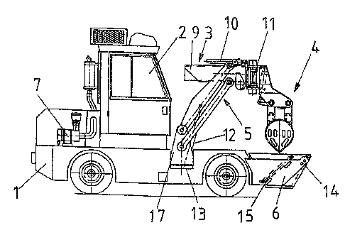
Fig. 1 shows a vertical view of a vehicle for collecting
crust and carbon reminders from an electrolytic
cell,
Fig. 2 shows a front view of the same vehicle,
Fig. 3 shows a vertical view of an alternative design of
such vehicle,
Fig. ~ shows a rear view of the vehicle shown in Fig. 3,
Fig. 5 shows the same vehicle as is shown in Fig. 4, but
with the collecting equipment being in a streched-
out position.
The vehicle comprises, as is appearent from Fig. 2 and Fig.
2, of a chassis 1 carried on wheels with a propelling engine
7, and drivers cabin 2. On the chassis close to the cabin 2
is provided a turnable collecting device in the form of a
grab bucket 4 being disposed on the outer end of derrick
arrangement 3,5. The derrick arrangement comprises an upper,
basically horizontal disposed telescopic boom 3 which can be
raised or lowered by means of parallel stays 5 on a turntable
17. The lifting and lowering is accomplished by means of a
piston/cylinder device 12. The boom 3 comprises an outer
telescopic element 8 and an inner guide element 9.
The telescopic element 8 is slideably disposed relative to
the element ~ by means of a piston/cylinder device 10.

p' f
gird ~.~ ".~ :~~
4
With regard;to the grab bucket 4, this is turnably mounted to
a telescopic element 8 by means of a joint 11. A piston/
cylinder device (not shown) is provided to turn the grab 4 in
both directions. The collecting device 3,4,5 is, as indicated
above, turnably disposed on the chassis 1. fore precisely, it
can, by turning the turntable 17, be turned in each direction
relative to the vehicle. To obtain low construction height,
the collecting device is disposed in a transversal recess 13
in the chassis 1. In Fig. 1 is shown the collecting device in
a lifted position where it reaches in the forward direction
of the vehicle, whereas Fig. 2 shows the collecting device
being swung sideways relative to the vehicle in a lowered
position where the grab bucket is open and in a lifted posi-
tion where the grab bucket is closed (dotted lines).
Besides, the vehicle is at its forward part provided with a
container 6 for temporarily keeping the crust and carbon
reminders. In the example shown in the drawings, the con-
tainer is swingably mounted on the chassis by means of rings
14, and can tilted to be emptied by means of a piston/
cylinder device 15.
In Fig. 3-5 is shown an alternatively designed vehicle ac-
cording to the invention. Here, the collecting device is also
provided in a recess on the chassis at its midle, but it is
not turnable sideways like in the previous example. The
reason for not doing so, is that there is provided a platform
18 above the collecting device resting on four poles 16. On
the platform is turnably mounted a lifting boom 19 for lift-
ing and positioning of the anodes on the electrolytic cells.
The lifting boom 19 is telescopic and can, if necessary be
turned 360 °C about a bearing 20. Hydraulic piston/cylinder
devices 21,22 provides for the necessary turning and lower-
ing/lifting of the lifting boeim.

,; ~~
~;635~~~!5 _'~
With regard;to the collecting device, it is composed of an
interlinked parallel stay arrangement, comprising inner
parallel stays 23 being linked with outer parallel stays 25.
Each of 'the parallel stays 23,25 can be turned by means of
hydraulic piston/cylinder devices 27 respectively 28.
The vehicle according to Figs. 3-5 is also provided with a
container 29. The container is however provided in a recess
in the chassis between the parallel stays 23. Fig. 4 shows
the container in a lifted (tilted) position arid in a resting
position.
Fig. 5 shows the boom 30 for the collecting equipment in an
outer position and in an inner position (dotted lines).
Further is shown the lifting boom 19 in an outer position
with an anode 31 connected thereto. Still further Fig. 5
shows an hydraulic pressure device 32 which is provided to
hold the anode hanger against the anode beam 33 of the elect-
rolytic cell in connection with an anode changing operation.
The pressure device 32 is slideably mounted on a guide 34.
It should be noted that the engine 7 and cabin 2 shown in
Figs. 3-5 are each disposed at one end of the chassis.
The advantage with the embodiment of 'the invention shown in
Figs. 3-5, is that it represents a compact solution where the
collecting of crust and carbon reminders as well as the
exchange of anodes can be accomplished by means of one vehic-
le. As mentioned above, a motar (not shown) provides the
propelling e~f the vehicle. Hydraulic transmission is ad-
vantageously chosen because the hydraulic pump also may
provide pressure fluid for the hydraulic piston/cylinder
devices. It should also be noted that the invention as defin-
ed in the attached claims is not in any way limited to the
use of hydraulics. Thus, it may as well be used a mechanical
or electro-mechanical driving arrangement.

Representative Drawing
A single figure which represents the drawing illustrating the invention.
Administrative Status

2024-08-01:As part of the Next Generation Patents (NGP) transition, the Canadian Patents Database (CPD) now contains a more detailed Event History, which replicates the Event Log of our new back-office solution.

Please note that "Inactive:" events refers to events no longer in use in our new back-office solution.

For a clearer understanding of the status of the application/patent presented on this page, the site Disclaimer , as well as the definitions for Patent , Event History , Maintenance Fee  and Payment History  should be consulted.

Event History

Description Date
Inactive: IPC from MCD 2006-03-11
Time Limit for Reversal Expired 2005-01-31
Letter Sent 2004-02-02
Grant by Issuance 2002-06-11
Inactive: Cover page published 2002-06-10
Pre-grant 2002-03-27
Inactive: Final fee received 2002-03-27
Notice of Allowance is Issued 2001-12-17
Letter Sent 2001-12-17
Notice of Allowance is Issued 2001-12-17
Inactive: Approved for allowance (AFA) 2001-12-03
Letter Sent 2001-10-23
Reinstatement Request Received 2001-10-02
Reinstatement Requirements Deemed Compliant for All Abandonment Reasons 2001-10-02
Amendment Received - Voluntary Amendment 2001-10-02
Inactive: Abandoned - No reply to s.30(2) Rules requisition 2000-10-02
Inactive: S.30(2) Rules - Examiner requisition 2000-06-02
Inactive: IPC assigned 1999-01-29
Inactive: IPC removed 1999-01-29
Inactive: IPC assigned 1999-01-29
Inactive: First IPC assigned 1999-01-29
Inactive: IPC assigned 1999-01-29
Letter Sent 1997-10-16
Inactive: Status info is complete as of Log entry date 1997-10-14
Inactive: Application prosecuted on TS as of Log entry date 1997-10-14
Request for Examination Requirements Determined Compliant 1997-09-25
All Requirements for Examination Determined Compliant 1997-09-25
Application Published (Open to Public Inspection) 1991-08-03

Abandonment History

Abandonment Date Reason Reinstatement Date
2001-10-02

Maintenance Fee

The last payment was received on 2001-12-05

Note : If the full payment has not been received on or before the date indicated, a further fee may be required which may be one of the following

  • the reinstatement fee;
  • the late payment fee; or
  • additional fee to reverse deemed expiry.

Patent fees are adjusted on the 1st of January every year. The amounts above are the current amounts if received by December 31 of the current year.
Please refer to the CIPO Patent Fees web page to see all current fee amounts.

Fee History

Fee Type Anniversary Year Due Date Paid Date
Request for examination - standard 1997-09-25
MF (application, 7th anniv.) - standard 07 1998-02-02 1997-12-23
MF (application, 8th anniv.) - standard 08 1999-02-01 1998-12-15
MF (application, 9th anniv.) - standard 09 2000-01-31 1999-12-14
MF (application, 10th anniv.) - standard 10 2001-01-31 2000-12-01
Reinstatement 2001-10-02
MF (application, 11th anniv.) - standard 11 2002-01-31 2001-12-05
Final fee - standard 2002-03-27
MF (patent, 12th anniv.) - standard 2003-01-31 2002-12-18
Owners on Record

Note: Records showing the ownership history in alphabetical order.

Current Owners on Record
HYDEQ A.S.
Past Owners on Record
ARNT OVE HOLSæTER
KJARTAN DRõNNESUND
Past Owners that do not appear in the "Owners on Record" listing will appear in other documentation within the application.
Documents

To view selected files, please enter reCAPTCHA code :


To view images, click a link in the Document Description column. To download the documents, select one or more checkboxes in the first column and then click the "Download Selected in PDF format (Zip Archive)" or the "Download Selected as Single PDF" button.

List of published and non-published patent-specific documents on the CPD .

If you have any difficulty accessing content, you can call the Client Service Centre at 1-866-997-1936 or send them an e-mail at CIPO Client Service Centre.


Document
Description 
Date
(yyyy-mm-dd) 
Number of pages   Size of Image (KB) 
Description 2001-10-01 6 222
Claims 2001-10-01 2 49
Representative drawing 2002-05-15 1 23
Claims 1993-12-10 2 54
Abstract 1993-12-10 1 14
Drawings 1993-12-10 3 102
Description 1993-12-10 5 205
Representative drawing 1998-07-15 1 17
Reminder - Request for Examination 1997-09-29 1 117
Acknowledgement of Request for Examination 1997-10-15 1 178
Courtesy - Abandonment Letter (R30(2)) 2000-12-10 1 171
Notice of Reinstatement 2001-10-22 1 173
Commissioner's Notice - Application Found Allowable 2001-12-16 1 166
Maintenance Fee Notice 2004-03-28 1 173
Correspondence 2002-03-26 1 45
Fees 1995-12-12 1 34
Fees 1996-12-18 1 40
Fees 1994-12-07 1 43
Fees 1993-12-19 1 22
Fees 1992-12-17 1 21