Language selection

Search

Patent 2035670 Summary

Third-party information liability

Some of the information on this Web page has been provided by external sources. The Government of Canada is not responsible for the accuracy, reliability or currency of the information supplied by external sources. Users wishing to rely upon this information should consult directly with the source of the information. Content provided by external sources is not subject to official languages, privacy and accessibility requirements.

Claims and Abstract availability

Any discrepancies in the text and image of the Claims and Abstract are due to differing posting times. Text of the Claims and Abstract are posted:

  • At the time the application is open to public inspection;
  • At the time of issue of the patent (grant).
(12) Patent Application: (11) CA 2035670
(54) English Title: KWIK-KRIB/SUPER FORMS
(54) French Title: COFFRAGES A ASSEMBLAGE RAPIDE
Status: Deemed Abandoned and Beyond the Period of Reinstatement - Pending Response to Notice of Disregarded Communication
Bibliographic Data
(51) International Patent Classification (IPC):
  • E04G 9/06 (2006.01)
  • E01C 19/50 (2006.01)
  • E04G 9/00 (2006.01)
  • E04G 11/00 (2006.01)
  • E04G 11/36 (2006.01)
  • E04G 13/00 (2006.01)
(72) Inventors :
  • LUSTIG, WILLIAM H. (Canada)
(73) Owners :
  • WILLIAM H. LUSTIG
(71) Applicants :
  • WILLIAM H. LUSTIG (Canada)
(74) Agent:
(74) Associate agent:
(45) Issued:
(22) Filed Date: 1991-02-04
(41) Open to Public Inspection: 1992-08-05
Availability of licence: N/A
Dedicated to the Public: N/A
(25) Language of filing: English

Patent Cooperation Treaty (PCT): No

(30) Application Priority Data: None

Abstracts

English Abstract


-2-
The forming apparatus herein is horizontally
elongated and highly flexible. This apparatus is
constructed in various lengths and widths depending
on the users requirements. Hereon vertical tabs are
welded to the outside of the form at pre-determined
intervals to support angled iron to achieve horizontally
straight and sturdy forming. Whereby removing said
angled iron, you are able to achieve any desired
curve, whether concave or convex. A manually adjust-
able apparatus, consisting of two sections of tube
steel, one having a larger inside diameter than the
outside diameter of the other, wherein assembled are
slidable for horizontal adjusting of the said forms.
Hereon, welded to the said adjuster, a vertical round
tube having a set screw within, holds a vertical
steel rod. Herein the steel rod is driven into the
earth for stability and vertical adjusting is achieved
by means of the set screw. Hereon each length of form,
end plates are welded at ninety degree angles, whereby
two sections can be assembled by means of male and
female connection. By means of each section's ability
to connect, these forms can be assembled and dismantled
for transportation from job site to job site.


Claims

Note: Claims are shown in the official language in which they were submitted.

-7-
THE EMBODIMENTS OF THE INVENTION IN WHICH AN
EXCLUSIVE PROPERTY OR RIGHTS ARE CLAIMED ARE:
1. Slab forming apparatus for forming sections
of concrete slabs in a pre-determined area comprised
of elongated cold rolled steel of various lengths
and widths having pre-cut plates of cold rolled steel
welded at ninety degree angles to both ends of the
elongated cold rolled steel, wherein one end being
comprised of two pre-drilled holes and the opposite
end having two stud bolts welded to said steel plate,
wherein this procedure is carried out on several
sections of elongated cold rolled steel, can be
assembled precisely and effectively to form longer
sections which when placed upon the ground horizontally
can be arranged to hold concrete within its form to
achieve the desired shape and size of any given
slab of concrete.
2. The slab forming apparatus as stated in
claim 1 enhanced by a manually adjusting apparatus
fastened to the outside of the steel form by means
of welding, enables the said forms to be adjusted
in the horizontal and/or vertical directions.
3. The slab forming apparatus as stated in
claims 1 and 2 characterized by steel tabs cut in
an "L" shape when welded to the outside of the form
at pre-determined intervals act as a permanent guide
for inserting angled iron to achieve and maintain
horizontally straight sections of forming. Whereas
curved sections are required, the angled iron can
be removed or omitted.
4. The slab forming apparatus as set forth
in the able claims 1 through 3 when characterized
by prefabricated right angled sections (inside and
outside) allows the user(s) to achieve accurate and
efficient square or right angle corners.

Description

Note: Descriptions are shown in the official language in which they were submitted.


Thls in~ention relates to a manually opera~le
concrete ~orming apparatu~. Wood forming is commonlv
used throughout the concrete ~orming industry. Woo~
forms mu~t be cut to fit the ~ob at hand. To achieve
curve~, the ~ood i~ usually ~oakea in water to make
it pliable~ Wocd forms are a~sembled l?y mean~ oî
wlre nails. The li~espan o~ wood Iorms range ~rom
five to twelv~ uses. Skilled workers are al~o needed
~or the ~et up o~ ~uch ~orming and can be ~ery time
eonsuming.
I have found that the~e di~ad~Tantages can be
o~ercome by u~ing cold rolled ~teel cut in various
lengths and width~ and attach~ng thereon an apparatus
to allow :or hori20ntal and ~ertl~al movement, which
15 permi ts e~tremely :~ast ~lne tunlng in the i`ormlng
proce~s~ ~y means of male ana female connector~,
the~ form~ can be quickly as~emblea wlthout the use
o~ wire nall3. Curve~ can be a~hi~ed rela~ively
ea8i:1y without br~aking ~r warping; also the~e forms
.~ 20 can achie~e and maintain curves which cannot be done
wlth w~d. Where~n s~raight ~ ineY are required,
~:~ angled iron plaeed ~n tab~ ~slded to the out3ide of
the ~orm will produce exact and ~peedy formin~
Ri~h~ angle ~ction~ ar~ availab~ for fa~t forming,
7~ usine the ~a~d male and ~emale connection ~or in~lde
or outside ri~ht angle~. A stake ~older i~ welded to
the hori20ntal and ~ertical ad~u~ter to allow for
po~itive and qulok ~Take o~tt1ne.
,
:tnventor Signab~

In the drawing 8:
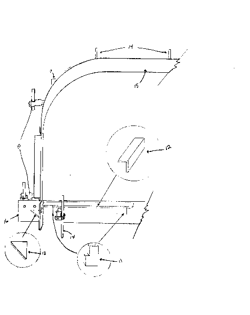
Fl~ a per~pec ti~e view of my inven1;ion .
Fig. 2 is a perspective d~tall ~riew o~ the
horl æontal and ~rert i cal ad ~ust er .
Flg. 3 i9 a cro3s~3ectional side ~iew of the
hori~ontal and vertlcal ad;~uæter.
Fig. 4 i~ a perspective view of the male and
fe~nale oonnectors.
~ig. 5 l~ ~ detail view o~ the r~ght angle
~ection of the ~orm.
Re~erring now to Flg~. 1 through 5, a ~ection
o~ the ~ald form 15 e:~ctenaY hor~ zontally on th~
ground ~howlng curved and ~trai.~t running section~.
Fig. 1 a ~t~el tab 11 î8~t~ned by mean~ o:~ welaing,
15~ hold~ angled iron 12 solidly ln place to aohie~re
~i;raight run~ing s~c1iion~, Whereby remo~ring angled
lron 12 you are able to curv~ or bend the form 15:
~o the desir~d ~3et~ing~ ~ig. 1 ~ho~ how horiæontal .
and;~ ~ert~l eal adJùster 10 hol~ in place the ~aid
: 2t) ~ ~taXe ~14 to ~ecure tha f`orm 15 in place Otl the
ground. Prefa~ricatea rieht .~angled ~eotion 1 li
; containl~g w~lded support 13 ~howæ how two ~otions
o~ the form 15 i~ as~embled by ~eans describad ~n
Fig :4 and Fi~. 5 known E19 male and ~emale connect:lon.
25: ~ef~rring to ~lg. 1 the lene~th and width OI the
orm 15 will ~ary: ~ep~ndin~ on the u~er~ requir~m~nt~.
However9~ throu~ my own studic~ wlth prototype~ and
w~rl~ing mode~, I îeel that the mo~t popular lengths
:
OI ~orm 15 wil~ be ln tw~, ~our, ~9 e~ght and ten
30 ~ fe~t ~ctlon~. These ~izes will allow Ior ea~y
ha~dling: and tran~portatlon. I feel that the width~
Or~ ~orm 15 wlll be :iour lnche~ to 8i~C ~nche~ w.~àe.
Re~erring now to Fig. 2 a square ~teel plate 22
havlng two hole~ 25 i~ fa~tened by mean~ of weld~ng to
35 a ~quare tube 20. A round tube 21 i~ also welded
Inventor Sign~t~

~5~
to square steel plate 22. Thi~ round tube ~1 i8
~nown as a stake holder, which holds the ~take
Flg, 1 :1 q . Another square tube ~ection 19 having a
smaller out~lde diameter than the in~ide dlameter
5 of ~quare tube 209 ~0 it can slide in a~d out.
Referring to ~ig . ~ this ~ iew shows s~uare
steel plate 22 ha~ing a threaded nut 26 welded ~o
the lnside. Whereon square tube 20 i~ welded ~quarely
to ~teel plate 22. Fig. 3:19 havin~ a stee~
10 pl~te 27 welded to one end, has bean drilled out and
a threadcd axtra long nut 26 welded ln place. A lon~
threaded bolt 24 i~ then ~crewed into threaaed nut~ ~6
to ;~oin both ~ection~ to îorm the adJu~ter which will
control the horiæontal movement, Square tube
15 ~ectlon 1g i~ then welded te the out~ide o:~ ~orm 15.
~hese ad~ust~rs 1~ are welded at ~ariou~ interval~,
and the amount required ~ s determined by the length
o ~ form 1 5 .
ReIerrlng to ~ . 4 an expl~aed view of the
20 male and ~emale connector plates. Each ~orm 15
ha~ing a plate welded~ at ~inety degre~ to Porm 15
wl:th~ two holes 18 and one plate wlth two stua ~olt~ 17.
::
:~ach of the form~ 15 had two o~ the ~tee~ plate~,
oppo~ite~ w~lded to the end of tha ~ai~ :~orm 15.
~5 R~erring now to ~ig ~ 5 showing a ri ght an~la
seotivn havin~ the Paoe(~ront~ Or the îorm 15 welaed
to two ~tQel plate~ at :~or~y-five d~grees ~ ha~ing
~uppsrt 13 wh~.~h ~s :~astened to both pl~te~ ~ these
plates havin~ pre~drilled hole3 18 and 1 7B, Stu~
30 ; bolt~ 17:B a~d bhe bolt~ 17A are then weldea into plac~.
: ~hl8 sec~ion o:~ form F~ g . 5 i~ u~d on outside rl~ht
angle~. ~o aohiev~ in~ide ri~sht angle~, a section
would be mad~ havlng th~ ~ud bolts 1 7A rev~rsea
by in~erti~g and welding them to steel plat;e having
35 holes 18.
In~r~ntor ignat~

f ~ r~ ~
~ ~
In detailing the mechanics and operation o~
my invention, I should al90 add that with a little
care ln oiling the movable part9 occa~ionally, and
cleaning periodically~ thi~ forming apparatus can
eaaily exceed one thousand asæemblies and tear downs,
My invention can also cut labour C08t by more than
f~ty percent and doe9 not require skillea ~orming
labourers to set up. ~he ~n~ention put ~orth in
thi~ document i~ manufactured from stock cold roll~d
~teel ~CRS) wh~ch i8 available at most ~teel
~upplier~. In my invention whlch I ~ve ae~cribed
with particular re~erence to th~ drawinga and was
intended for such u3es as conorete forming of deck~
patlo~, ~idewalksl and runway~, ~uch i~ not to be
:1:5 consldered a~ limiting it overall use~ in our
80ciety~ ~
:: :
::
:` ~:
~; .
Invantor ignatur'~~

Representative Drawing
A single figure which represents the drawing illustrating the invention.
Administrative Status

2024-08-01:As part of the Next Generation Patents (NGP) transition, the Canadian Patents Database (CPD) now contains a more detailed Event History, which replicates the Event Log of our new back-office solution.

Please note that "Inactive:" events refers to events no longer in use in our new back-office solution.

For a clearer understanding of the status of the application/patent presented on this page, the site Disclaimer , as well as the definitions for Patent , Event History , Maintenance Fee  and Payment History  should be consulted.

Event History

Description Date
Inactive: IPC from MCD 2006-03-11
Inactive: Inventor deleted 2001-09-05
Application Not Reinstated by Deadline 1993-08-04
Time Limit for Reversal Expired 1993-08-04
Inactive: Adhoc Request Documented 1993-02-04
Deemed Abandoned - Failure to Respond to Maintenance Fee Notice 1993-02-04
Application Published (Open to Public Inspection) 1992-08-05

Abandonment History

Abandonment Date Reason Reinstatement Date
1993-02-04
Owners on Record

Note: Records showing the ownership history in alphabetical order.

Current Owners on Record
WILLIAM H. LUSTIG
Past Owners on Record
None
Past Owners that do not appear in the "Owners on Record" listing will appear in other documentation within the application.
Documents

To view selected files, please enter reCAPTCHA code :


To view images, click a link in the Document Description column. To download the documents, select one or more checkboxes in the first column and then click the "Download Selected in PDF format (Zip Archive)" or the "Download Selected as Single PDF" button.

List of published and non-published patent-specific documents on the CPD .

If you have any difficulty accessing content, you can call the Client Service Centre at 1-866-997-1936 or send them an e-mail at CIPO Client Service Centre.


Document
Description 
Date
(yyyy-mm-dd) 
Number of pages   Size of Image (KB) 
Cover Page 1992-08-05 1 36
Drawings 1992-08-05 5 132
Claims 1992-08-05 1 58
Abstract 1992-08-05 1 47
Descriptions 1992-08-05 4 184
Representative drawing 1999-04-21 1 18