Note: Descriptions are shown in the official language in which they were submitted.
G F ~~Jg .
6oJ ~~ i ~ aJ ..k ~, vj
- 1 -
'°MOP WRINGE~2S AND BUCKETS °'
The invention relates to mop wringers and buckets
for use in wet mopping. It is particularly concerned with
wringers of the type which mount on a mop bucket and which
are manually operated, by means of a lever handle, to
squeeze out into the bucket a mop inserted in the wringer.
Known wringers of the foregoing type mount on the
rear wall of the bucket, which is severely stressed with a
buckling farce which has to balance the operating force
applied to the wringer handle. Thus the length of the
handle which can be used is limited by the necessity of
avoiding over-stressing of the bucket wall, which in turn
limits the squeeze pressure which can be applied to a mop.
A further disadvantage is that yielding of the bucket wall
results in a non-positive yielding "feel" when applying the
operating force to the handle.
A principal aim of the invention is to provide a
wxinger mounting which enables a :Longer operating handle to
be employed with a resultant improved wringing-out action.
According to the invention a mop wringer with a
lever operating handle mounts on the rear wall of a bucket
and when it is so mounted is supported on the side walls of
the bucket at or towards the front of the wringer, with the
wringer engaging the bucket in a manner which opposes the
f'~ J
- 2 -
tendency for the back of the wringer to lift off the bucket
when an operating force is applied to the wringer handle.
Preferably the mounting of the wringer on the rear wall of
the bucket provides -the engagement which opposes the
tendency for the back of the wringer to lift.
Front support of the wringer may be by means of a
cross member or side support members on the wringer, or a
wringer support member or members may be may be mounted on
the bucket. These arrangements can be employed to adapt
existing wringer and/or bucket constructions/designs to
provide wringer support in accordance with the invention.
Alternatively, front support of the wringer may be provided
by a supporting formation of the bucket, for example by
integrally moulded internal support ribs or ledges.
In a preferred arrangement a cross member .fixed
a~t the front of the wringer rests on the side walls, and
this member may engage the bucket side walls so as to
oppose arty tendency for the side walls to spread apart as
the wringer is operated. Such cross member is conveniently
manufactured from a length of flat metal strip attached to
the front of the bucket, with bent and twisted ends which
provide a formation to engage the bucket side walls. This
cross member may be manufactured and supplied Fox use to
adapt an existing wringer fox support on an existing bucket
in accordance with the invention.
In another arrangement, outrigger support members
integral with or having a firm connection to the sides of
,~,h?,a C
-~ L)
- 3 -
the wringer rest on the bucket side walls for support of
the wringer towards the front thereof. Alternatively,
support at the front of the wringer may be provided by a
separate saddle member which extends over and between the
side walls below the wringer, or separate individual saddle
members may respectively fit over the side walls and
project inwardly to support 'the wringer.
As the operating moment applied to the wringer
handle is no longer withstood by bending and buckling
forces applied to the rear wall of the bucket, but by an
upward tension at the rear wall and downward compressive
forces at the side walls, a longer handle can be used and a
more solid "feel" is provided as the operating force is
applied. The longer leverage thus obtained enables a
wringer to be manufactured with which the average cleaning
operative can achieve a completely wrung-out mop, whereas
with present handle lengths mops axe commonly incompletely
wrung out. At the same time thinner bucket walls will
often su:Efice with a moulded bucket, thus saving on the
cost of the moulding material and providing a cheaper
buclcet construction.
As the length of the handle is increased the
front floor support of the bucket may have to be moved
forwardly to prevent the bucket tipping over towards the
operative when operating the wringer. Thus the forward
floor support may be positioned in a lateral plane which is
disposed in front of the bucket and which preferably
r J ~~ i.,> ~~~ .~~. .iS. c,
contains the position on the handle to which 'the operative
force is applied with the handle at the wringing position,
The invention will now be further described with
reference to the accompanying drawings which illustrate, by
way of example, several embodiments of the invention. In
the drawings:
Fig. 1 is a perspective view of a hand-operated
wringer mounted on a mop bucket, in accordance with a
preferred embodiment of the invention;
Fig. 2 diagrammatically illustrates a rear mounting of
the wringer of Fig. 1;
Figs. 3A and 3B are respectively top and front views
of a cross member of the preferred embodiment;
Figs. 4 and 5 are partial views illustrating another
embodiment;
Figs. 6 and 7 are diagrammatic views respectively
illustrating two further embodiments; '
Fig. 8 is a plan view of a bucket of yet another
embodiment; and
Fig. 9 is a diagrammatic front view with the bucket
sectioned tin the line IX-IX in Fig. 8.
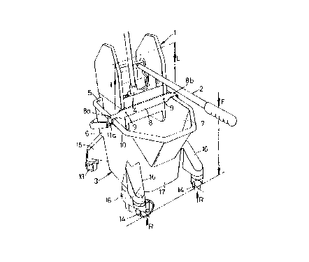
Fig. 1 illustrates a hand-operated wringer 1 with
an operating lever handle 2 and which mounts on top of a
mop bucket 3 as shown. Movement of the handle from a
generally upright resting position (not shown) to 'the more
or less horizontal and forwardly projecting position
("wringing" position) illustrated applies a squeeze
i.~ '~~ e~ t'~ ~~.. ~~ J
- 5 -
pressure to a mop, such as 4, inserted in the wringer 1
from above. The wringer 1 is of conventional general
construction and hence is not further described herein
except for the novel features associated with the
invention.
In accordance with the invention the wringer 1
mounts on the rear wall 5 of the moulded plastics bucket 3,
and it is supported at the front on the bucket side walls 6
and 7. Such front support is provided by a cross member 8
which is fixed at the front of the wringer 1, by suitable
fixings 9 such as screws or rivets, and which rests on the
rim 10 of the bucket. The ends 8a and 8b of the cross
member 8 hook over and seat on the rim 10 so as to oppase
any tendency for the side walls 6 and 7 to spread apart
during a wringing operation.
The cross member 8, which may be manufactured and
supplied for attachment to existing wringers to provide the
manifold advantages of the invention, is as shown more
particularly in Figs. 3A and 3H. As can be seen therefrom
the member 8 is formed from a length of flat metal strip,
fox example being of galvanized mild steel, with end
portions 8a and 8b twisted through 90° and then bent down
at right angles to provide end flanges 11a and 11b. Thus
the member 8 has end formations which hook over and seat on
the bucket rim 10. The main flat body Sc of the member 8
has suitable fixing holes 8d for the described fixings 9.
The rear mounting of the wringer 1 on the rear
- 6 -
wall 5 is such that it opposes a tendency for the back o:E
the wringer 1 to lift off the bucket as the operating force
is applied to the handle 2 as indicated by the arrow F. In
Fig. 2 there is illustrated an example of a suitable rear
mounting of the wringer 1, comprising a hook-like rear
formation which as the wringer 1 is fitted hooks around and
beneath the rim 10 of the bucket. This formation may be
provided on each of two space mounting projections 12 at
the rear of the wringer 1.
As a result of the rear mounting and front
support of the wringer 1 the wringing force is distributed,
largely as a compressive load on the bucket 3 by the cross
member 8 as indicated by the arrows L in Fig. 1. ~s the
wringing force is not withstood by buckling forces on the
rear wall, as it is in a conventional arrangement, the
wringing action has a "solid" feel and wringer deflection
does not dissipate the wringing forces. Furthermore, a
longer handle 2 can be employed which enables much greater
wringing forces to be applied for given operative effect.
The invention enables a handle to be used which in some
circumstances can be of the order of twice the length of
'the handles as normally used in the past.
For mobility the bucket 3 is mounted on four
corner castors, referenced 13 at 'the rear and 14 at the
front. As can be appreciated from the view of Fig, 1, the
increased length of the handle 2 not only increases the
wringing efficiency but it facilitates use of the handle 2
~r .
~~ c ~ Vii. ~ ~~~~ ~. e.'
7
for propelling and steering the bucket 3 on the castors
13, 14 . The rear castors 13 are fitted to floor support
outriggers such as 15 and the front castors 14 to
outriggers 16. The outriggers 15 are generally aligned
with the rear wall 5, and normally the outriggers 16 would
be similarly dispased with respect to the front wall 17 of
the bucket 3, as is shown in broken lines for the 7_eft-hand
corner in Fig. 1. However, in view of the increased length
of the handle 2 the front castors 14 are moved forwardly,
to prevent the bucket 3 tipping over forwardly when the
operating force is applied to the handle 2. The outriggers
16 are now cranked to extend forwardly so that the front
floor reaction forces indicated by the arrows R lie in a
lateral plane, in front of the main body volume of the
bucket 1, which plane also contains the arrow F. Thus the
castors are effectively brought into line with the vertical
handle load to prevent the bucket. tipping.
In the modification of Figs. 4 and 5 outrigcJer
support members 30 and 31 are positioned at the two sides
near to the front of the wringer 1. Each support 30 or 31
has a lower recess, 32 or 33, which seats on the bucket rim
10 to provide the same advantages as the cross member 8 of
the arrangement of Figs. 1 to 3. However, in this case the
rim 10 is engaged on both its inner and outer sides so that
the support members 30 and 31 act to strengthen the bucket
side walls against both inward and outward movement and
thus provide particularly firm lateral relative location of
y:3
~J ~' F~," lu .,~..
wringer and bucket. The cross member of the earlier
embodiment may if desired be modified so that it likewise
engages on both sides of the rim 10. The supports 30 and
31 are detachably secured to the wringer l, each having a
plug-in connection thereto as shown in Fig. 5. Flanged
projections 34 and 35 respectively engage at a lower open
ended slot 36 and an upper keyhole slot 37 at the sides of
the wringer.
Fig. 6 illustrates how the front support of the
wringer 1 may be provided by a separate saddle member or
sling 40 which at the ends 41 and 42 hooks over the side
walls 6 and 7. The member 40 extends below the wringer 1
under wringer cheek plates 43,44 near the front thereof to
provide direct vertical support. The support member 40 may
be sufficiently rigid to tie in the bucket sides and thus
oppose any tendency for outward spreading of the side walls
6 and 7.
rn the embodiment of Fig. 7, the single separate
saddle member 40 is in effect split unto two double-hook
like support members 50 and 51. At the upper ends 52 and
53 the members 50 and 51 respectively hook over the bucket
side walls 6 and 7. At the lower ends 54 and 55 the
members 50 and 51 respectively hook under the cheek plates
43 and 44 near to the front of the wringer 1.
The remaining embodiment of Figs. 8 and 9 employs
a design of bucket which enables the advantages of the
invention to be achieved with an existing wringer
;,,i~ i~'~ '"! !a .;~ .~
_ g
construction. The bucket 60 is moulded with internal
ledges 61 at the sides, these ledges 61 extending from the
bucket rear wall 62 for a distance slightly greater than
that spanned by the wringer 63. Front feet 64 of the
wringer 63, which are normally provided to enable the
wringer to be stood on the floor when not in use,
respectively rest on the ledges 61. This supports the
wringer 63 on the bucket side walls 65, of which the ledges
61 form part, at the front in accordance with the
invention. The wringer 63 mounts on the rear wall 62 as
before.
In that it enables a longer handle to be fitted
to the wringer the invention has important ergonomic
advantages in addition to that of better wringing-out of a
mop. Thus the invention provides excellent benefits for
people regularly using mop buckets and wringers,
particularly in lessening the back strain commonly suffered
by cleaning operatives. Not only can a given or improved
wringing action be achieved with far less effort than
hitherto, but the handle can be operated higher up so that
less stooping is involved when wringing out a mop.