Note: Descriptions are shown in the official language in which they were submitted.
2~36738
This invention relates to acoustic range finding
systems of the type in which an electro-acoustic transducer
transmits a pulse or shot of acoustic energy towards a
surface whose distance is to be measured, and subsequent
signals received from the transducer are monitored to
determine the temporal location of an echo from that surface.
Different transducer characteristics and operating
parameters are required for use in different circumstances.
In general, the best performance at short ranges is obtained
using transducers operating at relatively high frequency,
typically of the order of 50 kHz for ranges up to 20 metres
or so, whilst at longer ranges, transducers operating at
lower frequencies provide better performance, with
frequencies of the order of 12 kHz being suitable for very
long ranges of 50 metres or more, and intermediate
frequencies for intermediate distances. Broadly speaking,
the higher frequencies provide more sharply defined echoes
and better resolution, but are subject to more rapid
attenuation with distance particularly under adverse
conditions such as dusty environments, whilst low frequencies
are less subject to attenuation but provide more diffuse
echoes and lower resolution. The reflectivity and shape of
surfaces whose position is to be determined also varies with
frequency, and thus the identity of the substance whose
surface is to be measured, and its angle of repose, may
- 20~6738
influence the choice of transducer frequency. For example,
granular material with a sloping surface tends to reflect
low frequencies against a wall of the vessel thus producing
a weak direct echo, and strong indirect echoes reflect one
or more times from the wall of the vessel. This
characteristic is less marked with higher frequencies, but in
deep vessels it is not practicable to use as high a frequency
as would be desirable to mitigate this problem. It is common
practice to utilize longer pulse widths with lower
frequencies, both to allow the transmission of more sonic
energy, and to allow for the slower response time of low
frequency transducers. Since the received signal is usually
very small compared with the transmitted signal, and is
subject to high levels of noise, both the transmitter and
receiver are tuned close to the resonant frequency of the
transducer so as to optimise the signal-to-noise ratio of the
system. The transmission frequency is sometimes slightly
offset from the actual resonant frequency of the transducer
for various reasons; thus it is known to tune the transmitter
for optimum echo amplitude, which may occur at a slight
offset from the nominal resonant frequency, and also to shift
or sweep the transmitter frequency over a small range so as
to avoid nulls in the echo response due to interference
effects within the environment being monitored. Such
transmitter frequency changes are fairly small, and can be
accommodated within the bandwidth of the receiver.
United States Patent No. 4,199,246 (Muggli), issued
April 22, 1980, describes an ultrasonic ranging system in
which the transmitter is driven by a voltage controlled
oscillator, such that the frequency transmitted by the
transducer is changed in a predetermined manner over a
substantial range during the course of the transmitted pulse.
The bandwidth of the receiver is varied again according to a
preset pattern, during a subsequent period so that the
receiver bandwidth is narrowed with the passage of time
following the pulse, the passband of the receiver being
203~38
centred upon the lowest frequency transmitted. By
configuring the transmitted pulse so that a short initial
portion is transmitted at a relatively high frequency, which
is then reduced in one or more steps to a relatively low
S frequency, and configuring the receiver so that its initial
bandwidth is wide enough to pass the highest as well as the
lowest frequency, short range echoes of the high frequency
pulse components may be detected, but at longer ranges,
reception of the low frequency component and exclusion of
noise is optimized, by decreasing the bandwidth and thus
improving the quality factor (Q) of the receiver.
The Muggli system is subject to two constraints
which limit its applicability. The transducer itself must be
capable of operation over a wide range of frequencies, and
the noise immunity of the system at short ranges is very poor
because of the wide bandwidth of the receiver at those
frequencies. Neither of these limitations need be serious in
the camera control applications for which the Muggli system
is clearly primarily designed, involving as they do low power
transducers, comparatively short ranges, and environments
which are comparatively quiet at the frequencies of interest;
they are however highly significant in typical industrial
applications for which suitable transducers operating over a
wide frequency range are not generally available. Instead it
has been necessary to select a suitable transducer, and to
provide a transmitter/receiver system whose frequency
characteristics and output voltage are matched to the
transducer.
In order to overcome this problem, it is known to
provide transducers with an integral matched transceiver unit
and a preprocessor for received signals which converts
received echo information into data of standardized format
which is essentially independent of the transducer type.
This standardized data can then be transmitted for further
processing at a remote point, in a manner independent of the
20367'~8
transducer characteristics. Such an arrangement is disclosed
in United States Patent No. 4,700,569 (Michalski). Whilst
such an arrangement simplifies the remote processing unit for
a transducer, and enables it to handle data from different
types of transducers, this is at the expense of the addition
of complex circuitry to each transducer.
The present invention seeks to provide a control
unit for an acoustic ranging system which can be utilized in
conjunction with any of a wide range of different electro-
acoustic transducers, including combinations of transducersof different types in arrangements in which a number of
transducers are controlled by a single control unit. To the
best of applicant's knowledge, it has only hitherto been
possible to use a single unit to control multiple transducers
in a scanning arrangement where the transducers have had
substantially similar nominal requirements in terms of drive
frequency and potential.
According to the invention there is provided a
control unit for connection to an electro-acoustic transducer
to form an acoustic ranging system, comprising a transmitter
for generating shots of high frequency electric energy for
application to said transducer, a tuned receiver for
receiving and amplifying high frequency energy from said
transducer; means for digitizing output from said receiver,
and a control computer controlling said transmitter to time
said shots and for processing said digitized receiver output
to recognize therein features indicative of a primary echo
from a target being ranged, said unit further including
electronically controlled means for determining the operating
frequency of said transmitter, and electronically controlled
means for causing the tuning of said receiver to track the
operation frequency of said transmitter, and said control
computer further controlling the electronic tuning means for
the transmitter during each shot responsive to data relative
to characteristics of said transducer.
~036738
-- 5
Provision is preferably made in the unit for
selective connection to each of a plurality of transducers
under control of the computer, which stores separate data in
respect of each transducer which is utilized to control the
electronic timing means for the transmitter when connection
is established to that transducer.
Further features of the invention will become
apparent from the following description of a presently
preferred embodiment thereof.
In the drawings:
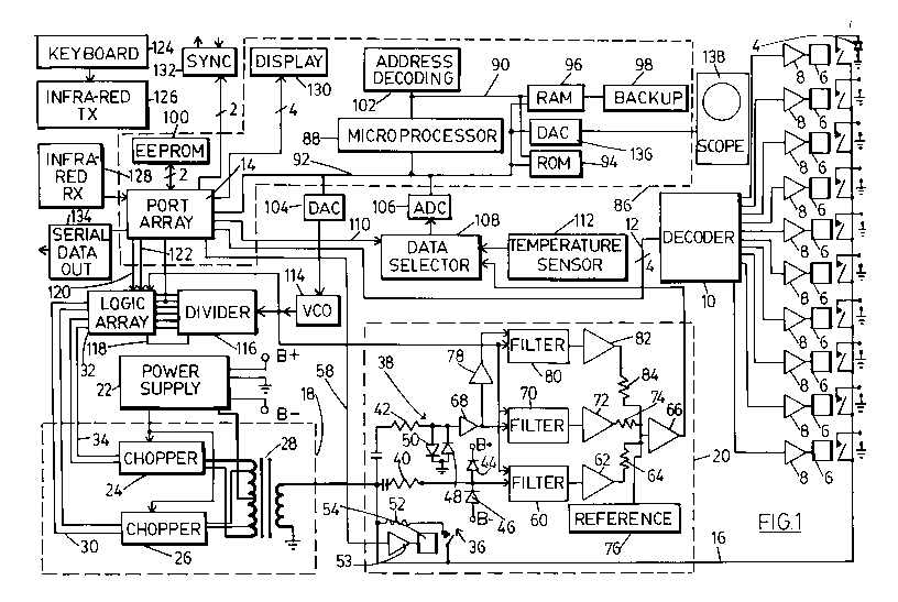
Figure 1 is a block diagram of an ultrasonic range
finding system incorporating the invention; and
Figures 2, 3, 4, 5, 6, 6A, 7 and 7A are flow
diagrams illustrating various features of a control program
for the system of Figure 1.
Referring to Figure 1, a control unit is shown
intended for connection to a number of ultrasonic transducers
4 of which only one is shown. The transducers are located in
a number of bins, silos, channels or other vessels being
monitored, each of which may be referred to as a point. In
general a single transducer will be located at each point,
but in some cases, as discussed in connection with Figure 7,
more than one transducer may be located at a single point.
Terminals of each transducer 4 are connected
respectively to ground and to a line 16 though normally open
contacts of a relay 6, itself controlled through a driver 8,
typically a transistor of suitable rating, by one output of
a decoder 10, any one output of the decoder can be selected
by applying a suitable combination of logic levels on lines
12 controlled by a multiple port array 14. The line 16 is
connected both to the output of a transmitter 18 and the
input of a receiver 20.
2036738
The transmitter 18 is formed by a converter unit
which receives direct current at low voltage from a power
supply 22 (which also provides suitable supply potentials to
the components making up the remainder of the unit) and
applies it through a chopper unit 24 or 26 to a transformer
28 whose secondary is connected between ground and the line
16. The chopper unit 24 comprises switching transistors
connected between one pole of the power supply 22 and the
ends of a primary winding of the transformer, the other pole
of the power supply being connected to a centre tap of the
transformer primary. The transistors are driven through
suitable driver amplifiers by signals on lines 34 from a
programmable logic array 32. The chopper unit 26 is similar,
except that its transistors are connected to intermediate
taps on the primary winding, and it receives its driver
signals on lines 30. Only one chopper unit is driven at a
time: the step-up ratio of the transformer 28 is higher when
the chopper unit 26 is used, and thus the output potential is
higher, for example 700 volts peak to peak compared to 350
volts peak to peak when chopper unit 24 is used. The
transmitter operates at a frequency determined by the signals
supplied to it by the logic array 32, which frequency is in
turn controlled by a voltage controlled oscillator 114 and a
divider 116 in a manner described further below.
The transducer signals from line 16 enter the
receiver 20 through clipping circuits 36 and 38 which protect
its input from the high output potentials generated by the
transmitter. The clipping circuits comprise, firstly,
current limiting resistors 40 and 42 and, secondly,
oppositely connected limiting diodes 44, 46, 48 and 50 to
limit excursions of the signals beyond the input capability
of the receiver components. The current limiting resistor 42
also acts as a load resistor as to apply a desired amount of
damping to the transducer thus enabling its Q to be adjusted
to a desired level. This loading can be altered by switching
-` 203~738
in a parallel resistor 52 by means of a relay 54 controlled
through a relay driver 53 by a control line 58 from the port
array 14.
The output of clipping circuit 36 is applied to an
electronically controlled bandpass filter 60, the centre
frequency of which is set by applying a clock signal which is
a multiple (in this example 50 times) of the desired centre
frequency. Such a filter is available under part no. ML2111
from Micro Linear, a similar component LMF100 also being
available from National Semiconductor. The output of the
filter is applied to a logarithmic amplifier 62 and thence
through resistor 64 to an input of a summing amplifier 66.
The output of the clipping circuit 38 is applied to
a 50db low noise amplifier 68, and thence to a filter 70,
logarithmic amplifier 72, and a resistor 74 respectively
identical to filter 60, amplifier 62, and resistor 64, to
the input of summing amplifier 66. The output of the
amplifier 68 is also applied to a further 50db amplifier 78,
and thence via a further identical filter 80, amplifier 82
and resistor 84 to the summing amplifier 66 together with a
reference input from reference generator 76. The receiver
output, proportional to the logarithm of that component of
the receiver input which is at the frequency set by the
filters, appears at the output of amplifier 66.
The arrangements described so far are generally
similar to those described in our U.S. Patent No. 4,596,144,
the essential differences being the provision for electronic
tuning of the filters 60, 70 and 80, the control of
transmitter frequency, the selectable output voltage of the
transmitter, and the selectable loading imposed by the input
circuits of the receiver. Whilst in each of the latter two
cases, only two selections are shown in the example
described, a wider selection could be provided; thus the
output voltage of the transmitter could be varied over a wide
-`- 20367~8
range utilizing a regulator circuit digitally controlled by
a digital-to-analog converter, or additional resistors 52
could be switched in or out of circuit. The disclosed
transmitter arrangement using additional taps on the
transformer 28 is advantageous since the impedance of the
transmitter output is reduced with voltage, which suits the
characteristics of typical families of transducers.
The transmitter 18 and receiver 20, together with
the decoder 10, are controlled by a computer 86, which
incorporates the port array 14 already mentioned. The
computer is based upon a microprocessor 88 having address and
data busses 90 and 92, and operating under control of a
program stored in read only memory 94. The computer is
provided with random access memory 96 for operating purposes
and storage of variables, the memory 96 being provided with
a short term back-up power supply 98 to preserve its contents
in the event of a short term interruption in the supply of
electrical power to the power supply unit 22. Variables
requiring longer term storage are stored in an EEPROM 100 or
alternative non-volatile electrically alterable memory
accessed through port array 14. Address decoding for various
peripherals is provided by a programmable logic array 102,
the peripherals including the port array 14 already
mentioned, a digital-to-analog converter 104 and an analog-
to-digital converter 106.
A data selector circuit 108 using transmission gates
controlled by a line 110 from the port array 14 allows the
analog-to-digital converter 106 to receive its input from
either the receiver 20 or a temperature sensor 112. The
output of the digital-to-analog converter 104 is applied to
the control input of the voltage controlled oscillator 114,
the output of which is applied both to the filters 60, 70 and
80 to control their centre frequency, and to a multi-stage
divider 116 through which the transmitter frequency is
controlled. The receiver tuning thus tracks the transmitter
2036738
frequency. The outputs of the divider are applied to the
logic array 32 so that the latter can detect when fifty input
cycles have been received by the counter from the oscillator
114 and apply a reset pulse on line 118 to the divider 116,
thus implementing a divide-by-fifty function to produce a
desired transmitter frequency. The array 32 also generates
appropriately phased outputs to drive the chopper 24 or 26,
under control of lines 120 and 122 from port array 14, which
determine respectively whether an output is provided to the
transmitter, and, if so, whether the output is on lines 30 or
34 so as to provide a high or low transmitter output voltage.
An input is taken from the output of the divider to the port
array so as to provide feedback data to the computer 86
concerning the frequency available to drive the transmitter;
the frequency is held to a desired value by controlling the
voltage applied to the VCO 114 by means of data applied to
the digital-to-analog converter 104. The small degree of
'hunting' in the VCO frequency which inevitably occurs is
desirable. It avoids problems, which can occur when the
transmitter frequency is rigidly maintained, due to valid
echoes being cancelled by interference effects within an
environment being monitored. Such effects are very frequency
specific and it is known to avoid them by deliberately
sweeping the transmitter frequency over a small range. The
present apparatus automatically avoids the problem without
separate provision being made to sweep the transmitter
frequency.
Provision is made for data input to and output from
the computer. A keyboard 124 is linked to the port array 14
by an infra-red transmitter 126 and an infra-red receiver
128, the arrangement being configured and programmed as
described in more detail in U.S. Patent No. 4,821,215, issued
April 11, 1989, and further lines from the array 14 control
a display 130 and a serial data transmitter 134. A further
digital to analog converter 136 provides an analog output to
an optional oscilloscope 138. Rather than providing a
2036738
-- 10 --
separate converter, the converter 104 may be used on a
switched basis during reception of the return signal after
the transmitter and filter frequencies have been set.
Further lines from the array 14 provide input and output from
a synchronization circuit 132, enabling multiple units in
accordance with the invention to synchronize their
transmission of ultrasonic pulses so as to avoid mutual
interference.
The computer 86 is also generally similar to that
of prior U.S. Patents Nos. 4,596,144; 4,831,565 and
4,890,266, apart from the provisions made and described above
for controlling the operating frequency and other
characteristics of the transmitter and the receiver; the
control program for operating the device, and its function
and operation, is also generally similar to what is described
in my prior patents, apart from those aspects of the program
which control and exploit the additional features of the
apparatus discussed above. These aspects are discussed
further below with reference to the flow diagrams of Figures
2 - 7.
Referring to Figure 2, the control program for the
apparatus has a normal measurement and display routine 200
operating in a program loop which includes a routine 202 to
test a flag, set from the keyboard 124, which indicates
whether the apparatus is to be operated in a "run" mode
looping through the routine 200, or a calibrate mode in which
it branches at 204 to a loop through an alternative routine
201 which contains procedures necessary to calibrate the
apparatus in various respects. It should be understood that
the procedures shown do not necessarily constitute all of the
calibration procedures that may be included in the loop but
only certain procedures relevant to the features of the
apparatus discussed above, which enable it to be matched to
and exploit the characteristics of different transducers.
The calibration loop tests for the entry, typically by an
2036~38
-- 11 --
operator from the keyboard, of various calibration requests,
and carries out such requests when they are detected. The
requests may also be entered automatically, for example as
part of a start-up sequence, or during intervals when
operating conditions in bins being monitored are found to be
suitable. For each request it will normally be necessary to
determine which transducer is to be calibrated. This
selection may be made manually from the keyboard, or
automatically in sequence, or according to availability as
part of an automatic calibration sequence. If only one
transducer is being controlled, this function could of course
be eliminated, but conveniently the identity of a transducer
to be calibrated is included in the request.
A first type of request which may occur is a request
206 to determine a variable TRANSDUCER_TYPE indicating the
type of a transducer 4 connected to the apparatus. If such
a request is detected, the subroutine 208 shown in more
detail in Figure 3 may be followed. Further requests 210,
214 and 218 are to determine and store in memory variables
SHORT_FREQ, LONG_FREQ and STEEP_FREQ. These represent
respectively the optimum frequency at which to operate the
transducer for short range measurements, the optimum
frequency at which to operate the transducer for long range
measurements, and the optimum frequency at which to operate
the transducer in order to obtain maximum accuracy, these
requests if detected being carried out by procedures
DETERMINE SHORT_FREQ, DETERMINE LONG_FREQ and DETERMINE
STEEP_FREQ. The first of these is shown in more detail in
Figure 4, the remaining two being generally similar.
Referring to Figure 3, the procedure DETERMINE
TRANSDUCER_TYPE causes the port array 14 to be programmed so
that the decoder 10 selects (step 300) the correct
transducer, and so that the logic array 32 selects lines 34
for the application of signals to the transmitter 18,
corresponding to a choice of the lower of the two transmitter
- 2036738
- 12 -
output potentials; this is selected so as to be within the
voltage ratings of all of the different transducers likely to
be utilized. For the purposes of the following description,
it is assumed that three types of transducer may be utilized,
having nominal operating frequencies of 13 kHz, 22 kHz and 44
kHz respectively.
In step 302, digital data is applied to the digital-
to-analog converter (DAC) 104 such as to provide an output
potential which, when applied to the VCO 114, causes the
latter to oscillate at 2.2 MHz, i.e. fifty times 44 kHz. The
VCO output is divided down to the latter frequency by the
combination of the divider 116 and the logic array 32. The
frequency is monitored by a line from the output of the
divider to the port array 14, and the data applied to DAC 104
is adjusted so as to obtain the desired frequency. The
output of VCO 114 is also applied to the filters 60, 70 and
so as to tune them to 44 kHz. When the desired
transmitter frequency has been attained, the lines 34 are
enabled briefly to permit a burst of 44 kHz energy to be
applied to that transducer 4 which has been selected by
decoder 10. The resulting output signal from the receiver 20
is digitized by analog-to-digital converter (ADC) 106, and
the samples stored in RAM 96 to form an echo profile of at
least an initial portion of the receiver response during a
ringdown period.
Initially, the receiver will saturate during the
transmitted pulse whilst the clipping circuits 36 and 38 are
operative, with this being followed by a ringdown period
during which the transducer will still be ringing following
application of the transmit pulse. If the transducer is a 44
kHz transducer, the energization will be at a frequency close
to the resonant frequency of the transducer, and a strong
pulse will be followed by substantial but diminishing ringing
which will occur during the ringdown period. If the
transducer is a 22 kHz or 13 kHz transducer, the energization
203673~
- 13 -
will be at a frequency remote from its resonant frequency,
and a weak pulse will be produced with little or no ringing.
The amplitude of samples of the echo profile
obtained during the ringdown period at a defined interval
after commencement of the pulse, for example 2ms, is measured
to provide an indication of the amplitude of the ringing
produced by the transducer.
The DAC 104 is then reprogrammed to adjust the
transmitter frequency to 22 kHz, and the above procedure is
repeated in step 304, and after further adjustment of the
frequency to 13Hz, again in step 306. Because of the longer
ringdown expected from the lower frequency transducers, the
average level of the samples over a period of typically 2 to
4 ms after commencement of the pulse may be determined.
lS The average levels determined in steps 302, 304 and
306 are then each compared with upper and lower thresholds in
steps 308, 310 and 312, for 13KHz, 22KHz and 44KHz
transducers respectively, the thresholds being selected
according to the characteristics of the transducers utilized.
The thresholds shown in Figure 3 are exemplary only. If the
level tested in any of these three steps falls between the
thresholds, the transducer type is set in step 314, 316 or
318, whilst if none of the levels falls within the specified
threshold, the transducer is considered defective or absent.
The transducer type setting so obtained can be utilized
directly, but if any ambiguity is possible as to transducer
type, for example if more than one type of transducer having
the same frequency may be utilized, it is preferred to
utilize a further step 320 which compares the transducer
frequency obtained for consistency with the frequency of an
operator entered transducer type, and displays a warning
message in the event of inconsistency.
- 2~367~8
- 14 -
It should be noted that the above procedure not only
determines the nominal operating frequency of a transducer,
but also verifies its proper operation in accordance with a
technique disclosed in United States Patent No. 4,831,565.
In order to obtain optimum performance from a
transducer of given nominal frequency, more precise control
over operating frequency is desirable, both to allow for
differences between different units, and for operation under
different circumstances. To provide a comprehensive
characterization of a particular transducer, we have found
that at least three, usually different, operating frequencies
should be determined, namely the optimum frequency SHORT_FREQ
for short range measurements, involving echoes within the
ringdown period, for which the size of the echo above the
level of ringing should be a maximum; the optimum frequency
LONG_FREQ for long range measurements involving echoes
outside the ringdown period, for which the maximum echo
amplitude should be sought; and the optimum frequency for
high accuracy measurements, for which the steepest rising
edge of the return echo should be sought. These frequencies
are determined by the procedures 212, DETERMINE SHORT_FREQ;
216, DETERMINE LONG_FREQ; and 220, DETERMINE STEEP_FREQ
respectively. In order to carry out these procedures, it is
necessary that an appropriate echo be generated, and it will
normally be desirable to carry out this part of the
calibration procedure prior to final installation of the
transducer being calibrated so that it may be aimed at an
appropriate target, such as a wall, at an appropriate
distance to generate a suitable echo for calibration
purposes. Calibration in situ will be dependent upon the
presence of a reflecting surface at an appropriate range or
ranges within a tank, bin, channel or silo being monitored.
The procedure DETERMINE SHORT_FREQ is shown in
Figure 4. As a first step 400, a further procedure SET
TRANSMIT VOLTAGE AND GET FREQUENCIES is called, which is
2036738
- 15 -
shown in more detail in Figure 5. In this latter procedure,
three variables, NOM_FREQ representing nominal transducer
frequency, MIN_FREQ representing minimum transducer
frequency, and MAX_FREQ representing maximum frequency are
all zeroed (step 500) No transmit voltage is selected at
this stage. In steps 502, 504 and 506, if the transducer
type is 13, 22 or 44, then appropriate values are stored as
the variables (steps 503, 505 and 507), representing the
nominal frequency of a transducer of that type, and maximum
and minimum frequencies between which a transducer of that
type may be operated. The transmit voltage as selected by
logic array 32 for application to lines 30 or 34 is selected
to be low (lines 34) for transducers of types 13 and 22, and
high (lines 30) for transducers of type 44. This is of
course a function of the particular transducers whose use is
exemplified, and in every case the voltage should be selected
to suit the actual type of transducer being used. We have
found in fact that at short ranges, there is little penalty
involved in operating a transducer below its maximum rated
voltage since both output amplitude and ringing fall
proportionately as the working voltage is reduced; at longer
ranges however, it is important to maintain the highest
possible transducer output so as to optimize signal to noise
ratio, and thus a transducer should be operated at its full
rated voltage.
Reverting to Figure 4, the transducer is arranged
relative to the test target at a range such that an echo will
be received from a short range, for example a range between
slightly more (0.2 meters) than the minimum range possible
and 3.5 meters. In step 402, a shot is transmitted operating
the transmitter at nominal frequency NOM_FREQ, and the signal
from the receiver is sampled and an echo profile stored. The
echo profile is processed utilizing known techniques to
identify the echo from the target, and its location on the
profile is stored as a variable POSITION. In step 404, a
203~73g
-
- 16 -
check is made that POSITION is within the specified range,
failing which the procedure is terminated.
Two files, for peak amplitudes and ring amplitudes,
indexed by frequency, are then cleared (step 406) and a
counter is set (step 408) to a number, for example 4, of
shots which are to be utilized at each frequency during the
procedure to be described below.
In step 410, a variable FREQUENCY is made equal to
MIN_FREQ. In step 412 a shot is then transmitted at the
frequency specified by variable FREQUENCY, the echo profile
is stored, and the echo from the target identified. The peak
value of the echo above the ringing level ahead of the echo
is stored in the peak file indexed by the value of FREQUENCY.
The amplitude of the signal at minimum range is stored in the
ring file, indexed by the value of FREQUENCY. The value of
FREQUENCY is then incremented (step 414), for example by 120
Hz, and unless FREQUENCY exceeds MAX_FREQ (step 416),
execution loops back to step 412. Thus the peak value of the
echo and the amplitude of the ringdown at minimum range are
tested and stored at intervals between the limiting
frequencies MAX_FREQ and MIN_FREQ.
The counter is then decremented at step 418, and if,
as tested in step 420, the count has not reached zero,
execution loops back to step 410 so that additional shots can
be taken at each frequency to avoid the effect of random
variations.
If the count has reached zero, the contents of the
peak and ring files are divided by 4 to average the stored
amplitudes, and the amplitudes stored for each index
frequency are compared to determine the frequency at which
peak amplitude exceeds the ring amplitude by the greatest
amount (step 422).
2036738
It should be noted that NOM_FREQ, MIN_FREQ, MAX_FREQ
and MINIMUM RANGE and transit voltage will vary according to
transducer type. The following examples are typical
NOM_FREQ MIN_FREQ MAX_FREQ MINIMUM VOLT-
RANGE AGE
44KHz Transducer 44KHz 38KHz 54KHz 0.3m High
22KHz Transducer 22KHz 16KHz 28KHz 0.6m Low
13KHz Transducer 13KHz 10KHz 16KHz 0.9m Low
The procedures DETERMINE LONG_FREQ and DETERMINE
STEEP FREQ are similar, except that ring file is not used,
the distance to the target being verified as great enough to
bring it well outside the ringdown period, and the variable
whose value is determined is different in each case, namely
LONG_FREQ and STEEP_FREQ. In determining LONG_FREQ, the
frequency providing maximum echo amplitude in the peak file
is determined, whilst in determining the slope of the leading
edge of the echo at position is determined and added to a
file analogous to the peak file, the frequency providing the
steepest slope being selected. The return signals during
these procedures can if desired be displayed on the
oscilloscope 138 to permit manual selection of optimum
frequency on the basis of an inspection of the display.
The normal measurement and display routine 200 (see
Figure 2) which is executed in the run mode is described in
more detail with reference to Figure 6 and 6A. The run loop
is entered at point 600 or reentered from the run/calibrate
test 200, the first step 602 being selection of the next
point or transducer location to measure, each point being
selected in rotation. In the next step 604, variables stored
in memory relating to that location, for example SHORT_FREQ,
LONG_FREQ, STEEP_FREQ TRANSDUCER_TYPE and TRANSMIT_VOLTAGE,
are recovered, and TRANSDUCER_TYPE is checked (step 606) to
determine whether it indicates that case the transducer is
- 2036738
- 18 -
either absent, defective or uncharacterised, in which case
and execution loops to step 202.
A shot is then transmitted at LONG_FREQ, and the
echo profile stored (step 608); according to requirements
this shot may be repeated several times to build an average
echo profile. In the following step 610, the stored profile
is examined and a probable true echo is selected, the
temporal position of the echo in the profile being stored as
a variable LONG_POSITION, and the confidence factor attached
to the selection being stored as a variable LONG_CONF. The
actual data processing used to perform this function does
not form part of the present invention. Further description
of suitable techniques can be found in my prior patents to
which reference has already been made above.
Steps 612 and 614 are`then performed, these being
similar to steps 608 and 610 except that transmission is at
SHORT_FREQ, and the position and confidence data is stored as
variables, SHORT_POSITION and SHORT_FREQ. Normally the shots
at SHORT_FREQ will be of shorter duration than those at
LONG_FREQ, since they are intended to gather short range
data; a short shot terminates earlier and has a shorter
ringdown period, thus permitting detection of shorter range
echoes and improving resolution.
The confidence factor SHORT_CONF is then tested
against a threshold SHORT_THRESH to determine whether the
confidence factor of the echo identified by the shot (or
shots) at SHORT_FREQ is sufficient to justify further
processing (step 616). If it is, SHORT_CONF is incremented
by a bias factor BIAS, and its excess as so incremented over
SHORT_THRESH is tested to see whether it exceeds the excess
of LONG_CONF over a threshold LONG_THRESH set for that
confidence factor (step 618). If it does, SHORT_POSITION is
transferred to a variable POSITION (step 620).
2036738
-- 19 --
If either of the tests of steps 616 and 618 fail,
a determination is made (step 622) whether LONG_CONF exceeds
LONG_THRESH, failing which the program loops back to step
202. Otherwise, LONG_POSITION is transferred to POSITION
(step 624). Whichever of SHORT_POSITION and LONG_POSITION
is transferred to POSITION, the POSITION variable is
processed (step 626) to convert it to one or more of a
distance, level or volume measurement which is stored in
memory and sent to display 130, in known manner.
The bias in favour of the result from shots at
SHORT_FREQ is because short range readings are usually more
critical in that they indicate a potential overfill or
overflow situation, and a significant short range echo thus
merits special consideration: in particular situations, it
may be preferred to apply no bias, or to bias selection in
the opposite direction to favour long range echoes, as when
detection of an empty or low-level situation is more critical
then an overfill or overflow situation. The entire procedure
is only exemplary of many programs that can exploit the
features of the present invention. If maximum accuracy of
measurement rather than maximum reliability in echo detection
is required, all shots may be taken at STEEP_FREQ, in place
of LONG_FREQ, or both LONG_FREQ and SHORT_FREQ.
The ability of the apparatus described to control
multiple transducers of different types opens the possibility
of utilizing more than one different transducer in a single
bin, silo or other container, so as to exploit the different
transducer characteristics. In general low frequency
transducers provide better performance at long ranges and
high frequency transducer provide better performance and
higher resolutions at short ranges as well as reducing the
minimum range that can be handled. Whilst three or more
transducers could be utilized in the same vessel, in most
cases two will be sufficient, and the exemplary procedure
described below utilizes two transducers although the
- 20367~8
- 20 -
principles disclosed could be extended to the use of
additional transducers.
Referring to Figures 7 and 7A, a modified form of
the procedure 200 is shown for use in an application in which
a high frequency transducer and a low frequency transducer
are mounted in the same vessel. For simplicity, certain
steps have been omitted: it should be understood that steps
similar to steps 602 and 606 in Figure 6 may be included, in
the latter case for each transducer. Steps 700, 702, 704,
706 and 708, carried out using the high frequency transducer,
are similar to steps 604, 608, 610, 612 and 614 described
with reference to Figure 6, except that the order of
execution has been changed, and the position and confidence
data obtained are stored in variables NEAR_POSITION,
MID_POSITION, NEAR_CONF and MID_CONF. Following three steps
710, 712, and 714, similar to steps 700, 706 and 708 are
performed using the low frequency transducer, so as to
generate position and confidence data stored in variables
FAR_POSITION and FAR_CONF.
The value of NEAR_CONF is then compared (step 716)
with a threshold value NEAR_THRESH, and if it exceeds it,
the value of NEAR_POSITION is stored in POSITION (step 722).
Otherwise (step 718), a further comparison is made to
determine whether the value of MID_CONF exceeds a threshold
MID_THRESH, in which case the value of MID_POSITION is stored
(step 724) in POSITION. Else yet a further comparison (step
720) is made to determine whether the value of FAR_CONF
exceeds a threshold FAR_THRESH, in which case the value of
FAR_POSITION is stored (step 726) in POSITION. If no
threshold is exceeded, the procedure terminates; otherwise
POSITION is processed (step 728), as in step 626.
The above described routines are exemplary only.
In the simplest case, the apparatus described in Figure 1
can be utilized in a single or multiple transducer
2036738
- 21 -
installation, regardless of the type of transducer utilized,
data relating to the transducer located at each point being
entered into the memory 96, and backed up by non-volatile
memory 100, so that the transmitter and receiver
characteristics may be controlled as described above in a
manner appropriate to the characteristics of the transducer
located at any particular point. In more sophisticated
applications, the apparatus may not only itself determine
the transducer parameters as described above, and exploit
them as described to improve performance of the apparatus as
also described, but also vary the ranging procedure utilized
according to the signals received. For example, in the
embodiment of Figure 6, the selection of the use of
STEEP_FREQ in place of LONG_FREQ, or both SHORT_FREQ and
LONG_FREQ, might be responsive to the confidence factors
measured, with STEEP_FREQ being used as long as the
confidence factor of the selected position value remained
above a certain threshold higher than LONG_THRESH, and
possibly also SHORT_THRESH, with LONG_FREQ, and possibly also
SHORT_FREQ being used only when low confidence factors make
it desirable to enhance the probability of echo recognition
at a possible slight expense in terms of accuracy.