Note: Descriptions are shown in the official language in which they were submitted.
2~3~3
Express Mail No. RB111332298
METHOD AND APPARATUS F~R CONTINUOUS
NON-INVASIVE BLOOD PRESSURE MONITORING
BACKGROUND OF THE INVENTION
1. Field of the Invention
The present invention relates to using pulse wave parameters
for continuous, non-invasive blood pressure (CNIBP) monitoring,
thereby obviating ill effect on the comfort and well being of the
subject whose blood pressure is being measured.
2. Prior Art
U.S. Patent No. 2,658,505 to Sheer discloses an arterial
pulse wave velocity meter, and proposes to calibrate it in ter~s
of blood pressure, to use it to indicate blood pressure and
deviations in blood pressure, and to do so continuously and for
hours, without difficulty and without discomfort to the patient.
U S, Patent No. 2,875,750 to Boucke et al proposes measuring
blood volume changes due to the arterial or venous pulse, and
combining such measure with an independent measure of systolic or
diastolic blood pressure for continuously indicating both
systolic and diastolic blood pressure without the danger of
injury or discomfort to the patient
U.S Patent No. 2,944,542 to Barnett et al proposes using
photo or impedance plethysmography in measuring pulse wave
velocity, and in measuring changes in blood pressure.
U.S. Patent No. 3,090,377 to Salisbury et al proposes
measuring transit time of an arterial pressure pulse, and
empirically interpreting it as a measure of diastolic or systolic
pressure.
U.S. Patent No. 3,095,872 to Tolles proposes measuring
modulation of the arterial pulse wave by injecting a higher
:
.. . . . .
2036~
frequency wave into the blood flow in an artery. The modulation
is interpreted as blood pressure variation, and is indicated as
blood pressure by an indicator calibrated in accordance with
blood pressure as determined by conventional techniques.
U.S. Patent No. 3,132,643 to Baum et al proposes measuring
"average pressure or essentially the difference between systolic
and diastolic pressures~ as functions of elapsed times beginning
with an electrical cardiac signal and ending with pulse signals.
~ .S. Patent No. 3,412,729 to Smith, Jr. proposes measuring
pulse pressure photoplethysmographically, and combining such
measurement with a measure of systolic pressure in order to get
diastolic pressure.
U.S. Patent No. 4,030,485 to Warner proposes measuring pulse
pressure photoplethysmographically, and combining such
measurement with a measure of mean pressure in order to get
systolic pressure.
U.S. Patent No. 4,245,648 to Trimmer et al proposes measuring
rise and transit time of pulse pressure waves, computing systolic
pressure and diastolic pressure therefrom, and calibrating these
results against a conventional cuff-type sphygmomanometer.
u.s. Patent No. 4,425,920 to Geddes et al proposes measuring
diastolic pressure as a function of pulse transit time, and using
a microprocessor to relate that measure to a set point, for the
purpose of medicating a subject whose blood pressure is to be
controlled.
More recently, U.S. Patents No's. 4,807,638 and 4,869,262 to
Sramek and to Orr et al, respecti~ely, relate to the present
subject matter. Sramek proposes to monitor mean arterial blood
pressure as a function of arterial pulse propagation delay
determined from bioimpedance measurements. Orr et al, propose to
measure diastolic blood pressure as a function of heart rate and
blood pressure pulse transit time determined by sensing emission
of R-waves.
Carruthers et al, ~Validation of a New, Inexpensive,
Non-Invasive Minaturized blood-pressure Monitor~, Journal of
~03~
Ambulatory Monitoring, 19~8, Volume 1, No. 2, pp~ 163-170,
appears to relate to a commercial version of the subject matter
of the Orr et al patent.
It will be noted that the foregoing prior art refers
sometimes to transit time and sometimes to velocity. These terms
are functionally equivalent for my purposes, which do not
include, as an end, providing a measure of transit time or
velocity, as such. That is to say, the end measure to be
obtained is pressure (mean, diastolic, systolic, and/or pulse),
and the application of particular means I adapted to this end can
be explained in terms of either transit time or velocity.
Note that the fundamental entity is transit time, i.e., the
velocity is given in essence by transit time, inasmuch as the
path taken by the pulse wave is the same in either case. I
therefore describe below, and claim, using the prior art
convention of referring either to transit time or velocity.
Various electrical and hydraulic events occur in the
cardiovascular system, and from them one can determine time
markers signaling the beginning and ending of the time interval
which is to be taken as transit time for the pulse wave. This
time interval ideally is the time it takes for the aortic
pre~sure wave to go from one polnt to another in the
vasculature. Thus, when the aortic valve opens, that event can
be detected and signals the aortic pressure minimum. A little
before the aortic valves open, the R part of the QRS complex
occurs, and also that can be detected. The Q point can also be
used as such marker.
Further on in the vasculature, the pulse pressure occurs, and
cardiovasculature correlates of pulse pressure can be detected in
many known ways, for determining fiducial points. In particular,
change in arterial blood volume may be measured in a selected
portion of microvasculature perfused by arterial blood. In the
prior art, such measurement is known as plethysmography and has
been caried out in terms of change in impedance, optical density,
flow, etc., of the blood in the selected portion of tissue.
--3--
, ,: .
- 203~
Using various combinations of the foregoing events and
changes, in the past one has been able to measure pulse wave
velocity, generally in terms of the time it takes for the pulse
wave to traverse some predetermined arterial path in the
vasculature. As is well-known, this velocity can be taken as a
measure of diastolic pressure, or, alternatively, of mean
effective pressure
The amplitude of the pulse wave, or the area under the pulse
wave, as measured by deflection of the artery wall, or by
pulse-caused blood volume changes at perfused tissue sites of the
subject, and so on, is taken as measure of pulse pressure, that
is to say, the difference between systolic and diastolic blood
pressure.
Having obtained pulse velocity and pulse pressure amplitude
measurements, one has inferred a diastolic pressure value from
the former, and has added the corresponding value of pulse
pressure amplitude thereto to get systolic pressure. On living
organisms, these measurements are made substantially
non-invasively and non-reactively by instrumentalities which
contact the external envelope of the organism without penetration
and with minimal force or other untoward disturbance of the
physiology of the organism.
In practice, the measurements described above are
supplemented in various ways in order to improve accuracy, etc.
Thus, the instrumentalities which derive systolic and diastolic
pressure vàlues f rom those measures are calibrated periodically
against pressure values obtained independently, say, by an
occlusive cuff system.
In a live human being or other organism having a heart, such
heart periodically creates blood pressure pulses in the arterial
vasculature of the organism. Thus, when the heart ~beats~, a
ventricle thereof contracts and increases the volumetric rate of
flow of blood in the vasculature. At the same time, the
contraction force creates a pulse of hydrostatic pressure which
propagates as a wave through the blood-filled vasculature. The
--4--
,' : ', .
'~
,. ~
2~3~3
front of this wave travels at a velocity which is much higher
than the velocity at which blood itself flows in the vasculature.
AS is known, the pulse pressure wave velocity depends both on
the elasticity of the vasculature and on the blood pressure in
the vasculature, so according to my invention, I measure
plethysmographic effects in tissue of the organism.Such tissue is
that in which the vasculature is embedded and perfuses the tissue
with arterial blood via a tree of arteries, arterioles and
capillaries.
In particular, I substantially continuously measure the
optical density of a given portion of said tissue. The amount of
blood in said given portion of said tissue fluctuates in response
to the pressure pulses created by ventricular contraction. The
blood in said portion is primarily that of the vascular bed in
said given portion of said tissue, and so is both venous and
arterial. As is well known, the venous outflow of the capillary
portion of the vascular bed is substantially constant, and
non-pulsatile, as compared to the arterial inflow. So, a~l else
being equal, fluctuation in optical density of the said given
portion of said tissue quantitatively corresponds to fluctuation
in arterial blood volume and, therefore, to the pressure pulse
amplitude.
Ae a first approximatiOn, and for some length of time, any
given individual organism's vasculature can be regarded as a
constant, at least insofar as is concerned the elasticity
thereof, and so, for that individual, during that length of time,
measuring pressure pulse wave velocity, as such can usefully be
thought to provide a measure of its blood pressure.
However, such individual organism's vasculature is frequently
not a constant, i.e., the organism breathes, may receive therapy,
is subject to physiological/psychological stress, and so on.
Hence, it beeomes likely that optical density of the said given
portion will, for a given organism, represent factors other than
just the effect of pulse pressure in a vasculature of given,
fixed elasticity
--5--
' ~:
. .
.. . .
. .
203~
According to my invention, the effect of said factors is
obviated by providing an optical density measurement which
distinguishes between the plethysmographic effect of pulse
pressure and plethysmographic effects due to the aforesaid other
factors.
In one form of my invention, I utilize two
photop:Lethysmographic devices of known construction. One device
has a probe which has a light source which illuminates a first
given portion of tissue with a beam of infrared (IR) light having
a wave length so chosen that the beam will be relatively
insensitive to the oxygen present in the blood which perfuses
said portion. The other device similarly illuminates a second
given portion of said tissue but at a location such that the
length of path, through the vasculature which perfuses said
portions with blood, and between the first given portion and the
heart, is different from the length of path through said
vasculature, and between the second given portion and said heart.
Each probe has an IR light sensor producing a signal whose
amplitude is proportional to the intensity of IR light received
from the corresponding said given portion. Also, the probes are
arranged such that their sensors receive substantially only light
from said given portions, i.e., not directly from their light
sources, and preferably not from other sources in their immediate
environment.
In the short run, as the given portions of tissue do not
change their dermal, fleshy, and other structural properties, so
the fluctuations of the sensor signals represent pulses of the
total blood volume in the given portions.
In accordance with my invention, I separate the pulsations
due to blood volume change from the total signal which contains a
much larger, but much more slowly varying component due to such
structural properties as I mention supra. The pulsations due to
blood volume change alone are a measure of pulse pressure, that
is to say, of the difference between systolic and diastolic blood
pressure in the vasculature.
. : . ,; `, . '
203~
According to my invention, also, I use the blood volume
pulsat:ions as markers by which a measure may be made of the
transit time of a wave front of a pulse pressure wave created by
ventricular contraction, in a path of predetermined length of
vascull~ture .
Further, according to my invention, after separating
pulsations due to blood volume change from the total
photoplethysmograph signal, the remaining signal's amplitude
reflects venous blood, non-blood tissue, and the effects of
possible iatrogenic, psychogenic, respiratory, and/or other
influences. Inasmuch as these influences, if not constant, or
absent, would introduce variable error into a measure of blood
pressure, under the assumption that the organisms vasculature was
constant, I therefore modify such measure by the above-described
signal remaining after the pulsations of blood volume have been
separated from the total probe signal.
As a result, once calibrated, for a given subject, on a
particular occasion, that calibration may be relied on for some
while despite the influences of stress, medication, breathing,
and so on. For longer periods of time the measurement of blood
pressure according to the invention needs also to be calibrated
from time to time against some standard. Such calibration may
be performed at intervals long enough that there need be
substantially no concern of the effect on the subject, due to the
instrument providing the standard, because in between such
standardizings, my invention can otherwise be relied on for
continuous monitoring of blood pressure with no ill effect on the
subject.
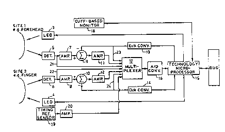
3. Brief Description of the Drawings
Figure 1 is a block diagram of the CNIBP monitoring system
according to the present invention and
Figure 2 is a diagram illustrating cardiac events
determinable from phonocardiographic and electrocardiographic
measurements, aortic and left ventricular pressure measurements,
. " ,'.,.'"
203~
and left ventricular volume measurements.
4. Detailed Description
In Figure 1, suitable sites 1 and 2, e.g , a living being's
forehead and finger, are illuminated by LED's 3 and 4,
respectively, and detectors 5 and 6, in turn are illuminated by
light returning from sites 1 and 2, respectively The LED light
oùtputs are fixed in amplitude, whereas the amplitude of light
returning from sites 1 and 2 is modulated by the vascular bed at
sites 1 and 2. Preferably, the LED's and detectors are
incorporated in probe structure (not shown) which isolate the
illuminated sites and the detectors from ambient light. Also,
such probe structure isolates the detectors from all the LED
light save that which comes from the illuminated sites.
The detectors 5 and 6, which convert the light they receive
into an electrical signal, in this case, a direct current. The
amplitude of this direct current is proportional to the amplitude
of the light received by the detectors, feed such signal to
transconductance amplifiers 7 and 8, respectively, each fitted
out with conventional circuitry (not shown in Figure 1) which
makes them convert the detector current at their inputs into
voltages at their outputs varying in amplitude in proportion to
the amplitudes of those currents at their inputs.
The output voltages of amplifiers 7 and 8 are next applied to
the respective summing junctions 9 and 10 along with the
respective output voltages of digital to analog (D/A) converters
13 and 14. The D/A converter output voltages result from
application to the converters of digital voltages from outputs of
a technology microprocessor module 15, which has processed
signals from an analog to digital (A/D) converter 16 receiving
analog voltages from a multiplexer 17, and converting the analog
voltages to digital form. Multiplexer 17 receives the output
voltages of amplifiers 11 and 12, and presents these analog
voltages, and others, one at a time, to the A/D converter 16.
A cuff-based pressure monitor 18 provides for applying a
digital voltage representing an independently, and generally
203~J~3
intermittently, measured blood pressure of the being whose
forehead and finger (or equivalent portions of perfused tissue)
provide sites 1 and 2.
A timing reference sensor 19 provides a voltage representing
the occurrence of some event in the cardiovascular system which
voltage, after amplification by an amplifier 20, is sampled by
multiplexer 17 and passed on thereby to A/D converter 16. Of
course, sensor 19 is not necessary if, as here, two LED-detector
sets are used.
The technology microprocessor module 15 is so termed because
it incorporates the pressure measuring algorithm for processing
the information available through multiplexer 17 and from monitor
18, by virtue of the corresponding technology represented by the
particular hardware and concept of measurement. Note that it is
not the nature of the hardware alone which determines what the
technology is. Thus, in oximetry, whereas only one of sites 1
and 2 need be used, both LED's would be necessary, so nothing
need be changed but the the spectral character of one ~ED and the
algorithm in the microprocessor, which would incorporate the
concept of oximetry instead of blood pressure measurement.
In the present case, each of LED 3 and 4 can be the same
infrared LED used in copending application of Baker et al, SN
190,661, filed May 5, 1988 and assigned to the assignee of the
present application. Likewise, each of the detectors 5 and 6,
and transconductance amplifiers 7 and 8 can be chosen to be the
same as the corresponding detector and current to voltage
converters of Baker et al.
I hereby incorporate herein, by reference, the Baker, et.al.
application. However, here the concern is not with frequency
multiplexing red and infrared signals, for a two signal channel
arrangement, but with time multiplexing.
According to the invention, sites 1 and 2 provide
plethysmographic information both as to pulse volume, that is,
the amount by which the volume of blood perfusing one of the
sites changes due to the pulse wave, and as to pulse wave
2 ~
velocity, as given by pulse transit time, that is, the length of
time it takes for a given pulse wave ~ront at the site nearer the
heart to show up at the more distal site.
Alternately, according to my invention, the plethysmographic
information I obtain could be relied on simply for pulse volume.
In that case, only one site, and hence one LED-detector set,
etc., would be required, but then it would be necessary to
utilize ele~trocardiographic or phonocardiographic information, a
capability represented by timing reference sensor 19, in order to
get a measure of pulse transit time or pulse wave velocity. The
single plethysmographic site would act as the distal site with
respect to the heart, which would then act as the nearer site, so
to speak. Again, ultrasonic flow detecting arrangements can
provide fiducial signals.
The function of the summing junctions 9 and 10, according to
the invention is to keep the slowly varying component of the
output voltage o the amplifiers 7 and 8 out of amplifiers 11 and
12. As disclosed in the Baker et al application, at this point,
most of the information carried by the frequency modulated
carrier waves represents the same information as is carried by
the aforesaid slowly-varying component, but which is eventually
removed after demodulation of the carrier waves. According to
the present invention, feedback loops, which extend via the
multiplexer 17, A/D converter 16, microprocessor 15, D/A
converters 13 and 14, to respective summing junctions 9 and 10,
prevent the aforesaid slowly-varying component from being applied
to the inputs of amplifiers 11 and 12. Consequently, the
amplifiers 11 and 12 can be constructed to have relatively high
voltage gain because they will receive, from the summing
junctions 9 and 10 just the relatively small AC component
remaining after summation at the summing junctions 9 and 10.
According to the invention, however, the feedback signals are
software-created in microprocessor 15 from the outputs of
detectors 5 and 6. Thus, in addition to the expectable
unnumbered connections depicted in Figure 1 as interconnecting
--10--
2~3~9~
variously the thus far described entities 3 through 20,
respective numbered connections 21 and 22 are shown between the
outputs of detectors 5 and 6 and multiplexer 17. In addition,
~etween the multiplexer 17 and the outputs of D/A converters 13
and 14 are respective numbered connections 23 and 24.
As disclosed in the above-identified Baker et al application,
the AC part of photoplethysmographic signal is extremely small as
compared to the total photoplethysmographic signal. Further the
total signal also inevitably contains a noise portion due to
residual ambient light among other things, and normally not much
different in magnitude from the AC part. According to the
present invention, connections 21 and 22 provide for applying the
total photoplethysmographic signals to the microprocessor 15.
The microprocessor of module 15 is programmed to convert those
signals into ones of slightly lesser amplitude, and to feed them
back via the respective D/A converters 13 and 14 to summing
junctions 9 and 10.
It will be noted that amplifying the total photoplethysmo-
graphic signal and providing A/D and D/A conversion with
resolutions adequate for handling the small A/C portion as part
of the total signal poses design difficulties and/or unfavorable
costs.However, as a result of the present invention, we are able
to utilize a 12 ~it A/D converter for A/D converter 6 and 8 bit
D/A converters for D/A converters 13 and 14 and, as well,
relatively high AC gain in amplifiers 11 and 12, none of which
would be feasible if the AC signal had to be processed as part of
the total signal.
The multiplexer 17, operating at a kiloHertz rate feeds the
site 1 and 2 signals, one at a time, to the microprocessor of
module 15, and are used then by the microprocessor of module 15
to create and to apply, again one at a time, to the corresponding
summing junctions, signals having magnitudes which are, say, 95%
of that of the site signals from which they resulted. These 95%
signals are subtracted at the summing junctions from the
then-current site signals from amplifiers 7 and 8. This leaves
: , :.............................. . .
.
203~ 73
5% signals for comfortable amplification by amplifiers 11 and 12
at a gain of, say, 25. That is, as each 95~ signal comes back to
a summing junction, it finds there the current signal from the
site which originally gave rise to the 95% signal. The sampling
rate of the multiplexer is high enough that the site signals will
not change so much that 95% of it will be significantly different
from the 95% signal from the microprocessor. As one skilled in
the art will recognize, signals from the detectors can be
interleaved, so to speak, with "dark" signals, and the like, for
the usual purposes.
All signals are sampled by the multiplexer 17, one after the
other and eventually the ultimate pressure measurement is output
by module 15 to BUS, for distribution to suitable conventional
means tnot shown) for indicating, recording, alarming,
controlling, or the like.
A basic procedure for the practice of my invention is, as
follows:
For a plurality of heart beats and preferably on each one of
consecutive beats throughout a time interval, the length of which
will depend on how often it is deemed necessary to recalibrate
against a conventional blood pressure monitor, I measure pulse
transit time, say between sites 1 and 2. On the same beat, and
at one of the sites 1 and 2, the total plethysmographic signal is
measured, say that sensed by detector 5 at site 1.
In the microprocessor module 15, suitable software then
estimates diastolic pressure as a value proportional to l/PTT,
where PTT stands for pulse transit time. The precise numerical
relationship is initially determined empirically.
Also, the software estimates pulse pressure, PP, as a
function of diastolic pressure, PD, and pulse volume, VP. In
turn, VP is determined by splitting the total plethysmographic
signal into its AC and DC components, as in the Baker et al
oximeter determination, and taking the ratio o~ the AC component
to the DC component (corrected for the effect bloodless tissue
would have on the photoplethysmograph~c signal).
-12-
.
20~ a~
In particular:
~ 2) PP=PD(expKVP-l), where K is a calibration constant,
empirically determined, which is redetermined each time that the
system is recalibrated against cuff-based measurements. N.B. All
empirical and recalibration operations are obtained from AC and
DC signal components determined just before inflating the cuff.
In particular:
(2) K=(ln(PSC/PDC))/VP, where PDC and PSC are diastolic and
systolic calibrating pressures as measured by the cuff-based
monitor.
In Figure 2, typical graphs of aortic pressure, left
ventricular pressure, left ventricular volume, electrocardiac
activity, and phonocardiac activity are shown for one arterial
pulsation of a single subject. As will be seen from the graphs,
there are more possibilities for fiducial points than I have
referred to, supra. Some, like ECG, do not exactly correlate
with the pulsation, whereas others do. Thus the R wave of the
ECG slightly precedes expulsion of blood from the left ventricle,
but on the other hand, the second heartsound of the PCG begins on
closing of the aortic valve. N.B. PCG, is shown here in the form
it has when taken directly at the heart, but there will be delays
before second sound will be detectible at sites distal to the
heart. However, one site would be more distal than the other so
the difference between the delays will give the transit time
between sites, independently of the time taken for the pulse wave
to get from the heart to the more proximal site.
AS will be evident from the foregoing, the instrumentalities
and procedures utilized in my invention are severally known to
the prior art. Therefore, I have not disclosed them herein in
detail because one of ordinary skill in the art will be able to
provide the same without resorting to patentable invention or
undue experimentation.
-13-