Note: Descriptions are shown in the official language in which they were submitted.
2~$~9
PATENT
55,534
1 PD-9975
DETECTION OF CONTAMINANTS IN A LIQUID STREAM
BACKGROUND OF THE INVENTION
The present invention relates to methods and
devices for detecting the presence of contaminants in a
liquid stream, and is particularly concerned with
preventing gas bubbles entrained in the stream from
falsifying the detection result.
A number of techniques are known for monitoring
liquids for various purposes. For example, in machinery
equipped with a system for circulating oil which sérves to
lubricate bearings, it is advantageous to monitor the oil
in order to detect and quantify metal particles which are
present in the oil as a result of bearing wear. According
to one known technique, the oil is caused to flow through a
passage where the oil stream is traversed by a light beam
which would be scattered by small metal particles in the
oil stream. Any scattered light is detected and the
detection result is processed to provide an indication of
the presence and concentration of such small particles.
In monitoring systems of this type, it has been
found that small air bubbles may also become entrained in
the oil stream and can effect scattering of the light beam
in a manner analogous to metal particles. This can produce
a false indication of the presence of metal particles in
9 3
PATENT
55,534
2 PD-9975
the stream, possibly resulting in the generation of an
alarm which will lead operating personnel to take
inappropriate corrective actions.
It is also known to induce pressure pulsations in
a liquid stream by directing a modulated light beam in~o
the liquid so that impurities therein will produce heat
that results in periodic thermal expansion of the liquid.
Such an arrangement is disclosed in U.S. Patent No.
4,738,536. An arrangement of this type will produce only a
low level of pressure modulation and appears to require the
presence of impurities in a sufficient concentration.
SUMMARY OF THE INVENTION
It is a primary object of the present invention
to reliably prevent the presence of gas bubbles in a liquid
stream from producing a false indication of the presence of
solid particles therein.
A more specific object of the invention is to
reliably detect the presence of small gas bubbles in a
liquid stream in a manner which is distinguishable from the
detection of solid particles in the stream.
Another object of the invention is to effect
particle detection in a manner which removes the influence
of gas bubbles from the detection result.
The above and other objects are achieved,
according to the present invention, in a method and
apparatus for detecting the presence of contaminants in a
liquid stream which may also contain gas bubbles, by:
mechanically generating an alternating
hydraulic pressure in the liquid stream; and
monitoring the response of gas bubbles in
the stream to the alternating hydraulic pressure.
Mechanical generation of the alternating pressure
within the liquid stream permits large amplitude pressure
variations to be created, resulting in a substantial
PATENT
55,534
3 PD-9975
deformation of any bubbles present in the liquid stream.
If the presence of bubbles is monitored by detecting the
scattering of light by the bubbles, such substantial
deformations will result in correspondingly large
variations in the amplitude of the detected scattered light
due to the presence of bubbles.
BRIEF DESCRIPTION OF THE DRAWING
Figure 1 is a schematic cross-sectional view of a
first embodiment of a system for implementing the present
invention.
Figure 2 is a cross-sectional view taken along
the line II-II of Fi~ure 1.
Figure 3 is a schematic cross-sectional view of a
second embodiment of a system for implementing the present
invention.
Figure 4 is a block diagram of a first embodiment
of a signal processing circuit used in the practice of the
present invention.
Figure 5 is a block diagram of a second
embodiment of such a circuit.
DESGRIPTION OF THE PREFERRED EMBODIMENTS
Referring to Figures 1 and 2, there is shown a
portion of a conduit 2, which may be a pipe or tube, for
conducting a stream of lubricating oil or other liquid
which is to be monitored for the presence of metal
particles. To perform such monitoring, the wall of conduit
2 carries a light emitter 4 which emits a light beam having
a defined width into the oil stream along a path 6. Any
metal particles passing through the light beam act as
scattering centers and light scattered in a given direction
will impinge on a light detector 8 which supplies an
electrical signal representative of the quantity of light
received to an output lead 10. As is known in the art,
2~31~9
PATENT
55,534
4 PD-9975
detector 8 may be disposed in line with axis 6 or, as
shown, may be laterally offset from axis 6.
The arrangement described thus far is known in
the art can be implemented with conventional devices.
Under various conditions, the oil stream conveyed
along conduit 2 may also carry entrained air bubbles which
will scatter light in a manner not detectably different
from small metal particles.
In order to differentiate between such air
bubbles and metal particles, conduit 2 is provided,
according to the present invention, with an acoustic horn
14 immersed in the oil stream and driven by an electrical
signal produced by a signal source 16 to produce an
alternating pressure signal which acts on the oil stream in
the region of light path 6. Preferably, acoustic horn 14
is of a type which focuses acoustic energy at a confined
focal region 18 which preferably coincides with the axis of
the light beam produced by emitter 4. The acoustic energy
produced by horn 14, particularly at focal region 18, will
cause the size of any entrained air bubbles to vary
adiabatically in synchronism with the alternating acoustic
energy, resulting in a corresponding modulation of the
light scattering produced by those air bubbles. This
acoustic energy will have a substantially smaller influence
on the light scattering behavior of small metal particles
since the size and shape of those particles will be
substantially uninfluenced by the acoustic energy.
In order to enhance the modulation of the
scattered light by small air bubbles, the frequency of the
signal produced by source 16, and thus of the alternating
acoustic energy produced by horn 14, is given a value
substantially greater than the quotient of the velocity of
the liguid stream through conduit 2 divided by the width of
the light beam produced by emitter 4. As a result, each
.
~3~
PATENT
55,534
PD-9975
air bubble passing through the light beam will experience a
plurality of pressure modulation cycles. Pre~erably, the
relation between the flow velocity, the width of the light
beam and the frequency of the alternating acoustic energy
produced by horn 14 is selected to subject each bubble to
at least 3 or 4 pressure modulation cycles. The number of
pressure variation cycles can be selected on the basis of
the characteristics, and particularly the response time, of
the circuit provided for amplifying the detector output
signal.
In the embodiment shown in Figure 3, the oil
stream is propelled through conduit 2 by a vane or piston
pump 20 which inherently applies a pulsating propulsion
force to the oil stream. Downstream of pump 20, conduit 2
is provided with a restriction 22 presenting an orifice
dimensioned to cause the pulsating propulsion force
produced by pump 20 to generate longitudinal pressure
oscillations which will act on air bubbles entrained in the
oil stream in a manner similar to horn 14. Light emitter 4
and light detector 8 are mounted on conduit 2 at a location
spaced downstream from pump 20 by a distance sufficient to
permit entrained air bubbles to stabilize after passing
through pump 20. The structure and operating speed of pump
20 can be selected to assure that entrained air bubbles
will influence the light beam during an appropriate number
of pressure pulsation cycles.
Pump 20 may be driven by a drive signal which
bears a relation to the pressure oscillations produced in
conduit 2 such that the drive signal can be processed to
produce an alternating signal which is synchronized with
the pressure pulsations. This alternating signal may be
used in signal processing circuitry to be described below.
~ ince the present invention generates a pressure
oscillation or pulsations mechanically, the presence of air
2 ~ 9
PATENT
55,534
6 PD-9975
bubbles will result in the production of large amplitude
modulations of the detected signal. Therefore, the
circuitry provided for amplifying and processing the
modulation components caused by air bubbles need not have a
high level of sensitivity, and can thus be constructed to
have a relatively short rssponse time.
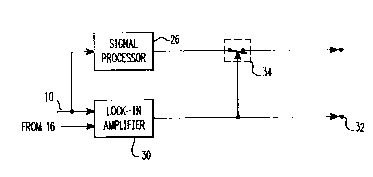
One embodiment of signal processing circuitry in
accordance with the present invention is illustrated in
Figure 4 where the signal on output lead 10 is supplied
both to a signal processor 26 of the type normally employed
for producing indications of the presence of solid
particles in the liquid stream and to one input of a lock-
in amplifier 30 which also receives, as a synchronous
signal, a signal corresponding to the horn driving signal
supplied by source 16 of Figures 1 and 2, or an alternating
signal produced from the signal driving pump 20 of Figure 3
as described above. Amplifier 30 produces a d.c. output
signal representative of the component of the signal in
lead 10 which corresponds in frequency to, and has a
selected phase relative to, the signal supplied from source
16. Thus, the output signal from amplifier 30 will be
representative of the degree of light scattering produced
by air bubbles in the liquid stream. The output of
amplifier 30 is connected to an output terminal 32 and to
the control input of an electronic switch 34 so that when
the output signal from amplifier 30 reaches or exceeds a
selected amplitude, an alarm may be triggered by a device
connected to terminal 32 and switch 34 may be opened to
block transmission of the detection signal produced by
processor 26.
While the arrangement illustrated in Figure 4 has
the advantage of a high degree of selectivity of signals~
produced by air bubbles and a high signal-to-noise ratio,
the amplitude of the light scattering signals produced by
2 ~ ~?~
PATENT
55,534
7 PD-9975
air bubbles in an arrangement according to the invention
will frequently be sufficient to allow the detection of
air bubbles to be effected by means of a simple amplifier
and bandpass filter tuned to the frequency of the signal
produced by source 16. This arrangement is less expensive
than systems of the type shown in Figures 4 and 5 and can
be suitably used with the embodiment shown in Figure 3 when
a signal synchronized with the alternating pressure is not
available.
Figure 5 illustrates a further arrangement
according to the present invention in which the output
signal component produced by air bubbles is employed to
directly modify the output signal produced by signal
processor 26 in order to directly provide a corrected
output signal indicative of solid particles in the liquid
stream. This circuit includes a scaler 38 connected to the
output of amplifier 30 in order to adjust the output signal
from amplifier 30 so that the scale of that signal is the
same as that of the signal produced by processor 26. The
signal produced by processor 26 will include a component
due to light sc~ttering from solid particles and a
component due to light scattering from air bubbles. The
scaling factor set by scaler 38 is selected, on the basis
of calibration tests, so that the output signal from scaler
38 is equal to that component of the output signal from
processor 26 which is the result of light scattering from
air bubbles. Thus, by subtracting the signal from scaler
38 from that produced by signal processor 26, in a
difference former 40, there is produced, at an output
terminal 44, a corrected signal corresponding to that
which would be produced by solid particles in the liquid
stream in the absence of air bubbles.
While the description above refers to particular
embodiments of the present invention, it will be understood
2 ~
PATFNT
55,534
8 PD-9975
that many modifications may be made without departing from
the spirit thereof. The accompan~ing claims are intended
to cover such modifications as would fall within the true
scope and spirit of the present invention.
The presently disclosed embodiments are therefore
to be considered in all respects as illustrative and not
restrictive, the scope of the invention being indicated by
the appended claims, rather than the foregoing description,
and all changes which come within the meaning and range of
equivalency of the claims are therefore intended to be
embraced therein.