Note: Descriptions are shown in the official language in which they were submitted.
i~)
2037~
~, .
LEG WARMERS
;:
TECHNICAL FIELD OF THE INVENTION
ffl e present invention relates to leg warmers
and, more specifically, to novel, improved leg warmers
which are designed for use out-of-doors, provide
superior protection from wind and cold, and have a
fastening systems that allows them to be easily donned
and doffed.
BACRGROUND OF THE INVENTION
. .
A number of leg warmers and other
superficially similar items of apparel such as leggings
and snakeproof chaps have heretofore been proposed.
Those of which we are aware are disclosed in: (a) U. S.
patent~ Nos. 1,930 748 issued 17 October 1933 to Giorda
for TROUSERS PROTECTOR; 2,014.208 issued
20 10 September 1935 to Parvin for FANG PROOF LEGGING;
3.538,914 issued 10 November 1970 to Myers for
~ ADJ~STABLE FASTENING DEVICE; 3.758,963 issued
,f. 18 September 1973 to Knight for SNARE BITE PREVENTING
;~ DEVICE; 4,110.845 issued 5 September 1978 to Chellis for
25 RAIN CHAPES; 4,382.301 issued 10 May 1983 to Hightower,
Jr. for SNARE PROOF CHAPS; 4,599,812 issued 15 July 1986
to Harmsen for LEGGINGS; 4,697,286 issued 6 October 1987
to Cho for PROTECTIVE THIGH AND KNEE GEAR; and 4,716,596
, issued 5 January 1988 to Hofman for GARMæNTS; (2) a
; 30 reissue of above-cited patent No. 4,382,301 (No. 32,506
dated 22 September 1987); (3) design patent No. 290,302
issued 16 June 1987 to Campbell for LEG WARMER; and (4)
an advertisement from Easy Riders magazine.
.
2~37~3(~
-2-
Many of the items of apparel disclosed in the
foregoing references would not be capable of keeping a
wearer's legs warm and protected from wind because of
their cut and/or the materials from which they are
fabricated.
The above-cited Giorda, ~yers, Rnight,
Chellis, Hightower, Jr., Harmsen, Cho, Hofman. and
Campbell patents, for example, disclose items of apparel
which would not be useful as leg warmers because of the
limited coverage of the wearer~s legs they provide.
And, of all of the items of apparel disclosed
in the cited references, only those disclosed in the
Campbell and Harmsen patents would appear to be made of
materials providing any significant protection from the
cold. ffl e leg warmers disclosed in the ~armsen patent
are nonetheless of limited utility because their
integral footwear would make it impractical to wear them
out-of-doors, especially in circumstances involving
travel on wet, snow covered, or muddy terrain.
Yet another drawback common to a number of the
heretofore patented leg coverings -- e.g., those
disclosed in the Parvin and Garland references -- is
that they are made of inflexible metals or have major
components fabricated from inflexible materials. As a
consequence. such leg covering~ would not afford the
freedom of movement required in many, if not most,
- circumstances in which leg warmers can be put to good
use. Fishermen, construction workers, sportsmen, and
others. all require more mobility than these leg
coverings would provide.
-3- 2037~30
':.'
Still another, and very important, drawback of the
prior art leg covers is that they employ fastening systems which
are inadequate because, if used in leg warmers, they would make
it too difficult to put the leg warmers on and then take them
off. Also, in the case of those disclosed in the Harmsen and Cho
; patents, for example, one part of the disclosed leg covering can
separate from the cooperating, underlying part in at least
localized areas, leaving an unintended gap therebetween. This
would be quite undesirable in a leg warmer as cold air could
penetrate through the gaps even if that was not wanted.
Furthermore, in most cases, no provision is made for adjusting
the previously disclosed leg coverings to fit the lower leg of
the particular wearer. This feature, though perhaps not
;~ absolutely essential, is obviously a highly desirable option.
A snug fit will exclude cold air, snow, and moisture and thereby
keep the wearer more comfortable.
~; SUMMARY OF THE INVENTION
The invention claimed provides a leg warmer which
comprises a wrap around panel dimensioned to extend from the foot
i 20 to the crotch of the wearer and to completely surround the
wearer's leg, the panel being fabricated entirely of flexible
- materials, comprising at least one layer of thermal insulation,
and having a top end and a bottom end and first and second,
completely separable edges extending from the bottom end to the
25 top end of the panel. A closure system is provided for so
continuously joining the vertically extending edges of the panel
together that the panel can be wrapped around the wearer's leg
and the closure system then employed to provide a seam which is
'~ resistant to the pa~age of cold air and moisture between the
30 first and second, vertically extending edges of the panel from
the bottom end of the leg warmer to the top end thereof. The
closure system includes a first means for joining the two edges
of the panel together over the major portion of the leg warmer
length and fastener means above the first closure system
'',
.
,:
-4- 2037~30
means and extending from the first closure system means to the
top end of the panel for fastening the first and second edges of
the panel together at the top end after the panel has been
wrapped around the wearer's upper leg and before the edges of the
panel are joined together by the first closure system means,
thereby facilitating the donning of the leg warmer and the
manipulation of the first closure system means by fixing the
edges of the panel together and holding the leg warmer to the
upper part of the wearer's leg.
10More particularly, there have now been invented, and
disclosed herein, certain new and novel leg warmers which do not
have the above-discussed, and other, disadvantages of heretofore
proposed leg warmers. Nor do they have the also above-discussed
disadvantages which other previously disclosed leg coverings
would have if one attempted to employ them as leg warmers or to
incorporate their features in leg warmers.
Generally speaking, the novel leg warmers disclosed
; herein include a wrap around panel having at least one layer of
thermal insulation and a closure system. After the panel has
been wrapped around the wearer's leg, the closure system is
employed to join the two vertically extending edges of the panel
together and thereby secure the leg warmer to the wearer's leg
in an essentially snow, moisture, and airtight relationship. A
suspender at the upper end of the leg warmer is attached to the
wearer's belt to keep the leg warmer from slipping after it has
been donned.
The leg warmers of the present invention have a unique
cut which results in their keeping the wearer's leg warm from
crotch to foot. At the same time, this cut furnishes ready
access to the front and rear pockets of the pants or trousers
over which the leg warmers are typically worn.
The leg warmers disclosed herein are designed to
~5~ 2037530
withstand heavy u~e out-of-doors by fishermen, construction
workers, sportsmen, and other persons. To this end, their wrap
around panels are preferably fabricated of a durable, wear
resistant material. They may also be designed to resist
penetration by rain and other moisture, snow, mud, etc.
Also, to the same end, the leg warmers of the present
invention may be equipped with a closure system providing an
adjustable fastener at the lower end of the leg warmer. This
allows the bottom of the leg warmer to be snugly fitted to the
wearer's leg, thereby excluding air, moisture, snow, and the
- like.
Closure systems employing zipperTsM are preferable to the
extent that they can be partially opened to provide ventilation
if the wearer becomes too warm. A single zipper with dual slides
can be employed. This allows two ventilation gaps to be created.
If a zipper is employed in the leg warmer closure system, an
additional fastener of the snap or pile-type is preferably
provided at the top of the leg warmer. This fastener is
`~ connected up first, securing the leg warmer to the wearer's leg.
This facilitates the starting and closing of the zipper.
Another type of closure system that can be employed in
the leg warmers of the present invention makes use of
cooperating, vertically extending strips of a pile-type fastener
material at the opposite edges of the leg warmer and extending
from its top end to its bottom end. While not as efficacious as
zipper-type fasteners in providing ventilation, those of the
character just described do have the advantage of being easy to
- secure to the wearer's leg at their upper end. They also provide
an adjustment at the bottom end of the leg warmer which allows
the above-discussed snug fit to be obtained.
The invention therefore seeks to provide leg warmers:
which are easy to put on, even over bulky work clothes,
and equally easy to subsequently take off;
which do not restrict or otherwise impede the wearer's
movements;
which are particularly suited for use in demanding out-
of-doors applications;
:: M
2037530
:
-6~
which extend from the wearer's foot to the
wearer's crotch and can be made essentially snow,
moisture, and airtight over this span;
which have a fastener at the bottom end
thereof that allows the leg warmer to be adjusted into a
snug, air excluding fit with the wearer's leg;
~ which have a suspender for attaching the leg
warmer to a wearer's belt and thereby keeping it from
slipping down;
which include a wrap around panel and a
closure system for securing vertically extendinq edges
of the panel together after the panel has been wrapped
around the wearer's leg;
which, in conjunction with the preceding
object, employ a closure system which includes a zipper
- and a fastener at the top end of the leg warmer which
- can be connected up first to hold the leg warmer to the
wearer's leg and make it easier to start and close the
.~' TM
zipper;
,-- 20 which, in conjunction with the preceding
object, are 80 constructed that the zipper can be
partially opened to provide one or more ventilation gaps
without the leg warmer becomng loose, falling off, etc.;
and
which have various combinations of the
just-enumerated, innovative features.
Other important aqxY~s and features and
additional advantages of the invention will be apparent
to the reader from the foregoing and the appended claims
and as the ensuing detailed description and discussion
proceeds in conjunction with the accompanying drawing.
. .
.; ,~ .
- 2~7~
`: --7--
BRIEF DESCRIPTION OF THE DRA~ING
.,~ .
In the drawing:
~: FIG. 1 shows how a leg warmer embodying the
'r,,' 5 principles of the present invention appears and fits
after it has been put on;
FIG. 2 shows how the leg warmer appears before
it is donned;
FIG. 3 is a side view of a wearer's lower body
` 10 and a second form of leg warmer which also embodies the
- principles of the present invention and features a
. zipper-type fastener and a pile-type fastener which is
connected up first to hold the leg warmer in place on
the wearer's leg and thereby make it easier to start and
.. 15 close the zipper-~type fastener;
FIG. 4 is a view, similar to FIG. 3. of the
leg warmer shown in the latter figure with the zipper
fastener partially opened to provide a ventilation gap;
~ IG. 5 is a view similar to FIG. 3, showing
~: 20 yet another leg warmer in accord with the principles of
the present invention, in this case a leg warmer which
- features a pile-type fastener at the bottom of the leg
warmer, allowing it to be adjusted to the wearer's leg
with a snug, snow, moisture, and air excluding fit.
FIG. 6 i8 a view, similar to FIG. 5, of the
leg warmer shown in FIG. 5 with a dual slide-type
. fastener of the leg warmer's closure system opened to
provide two ventilation gaps;
- FIG. 7 is a view, similar to FIG 6, of an
embodiment of the invention which differs from the
FIG. 6 embodiment primarily in that the FIG. 7
embodiment does not have a pile-type fastener at its
upper end;
. .
- 2~7~3~ -
.:
--8--
FIG, 8 i6 a fragmentary view of a leg warmer
: in accord with the principles of the present invention
which differs from tho~e embodiments illustrated in
FIG. 3-6 in that the pile-type fastener at the upper end
of the leg warmer has been replaced with a ~nap-type
fastener;
FIG. 8A is a fragment of FIG. 8 to a larger
scale and with a flap employed in the FIG. 8 leg warmer
. folded back to show details of a snap-type fastener
employed in that leg warmer;
FIG. 9 i6 a section through the leg warmer of
FIG. 3, taken substantially along line 9-9 of the latter
figure; and
FIG. 10 is a section through the leg warmer of
FIG. 5, taken substantially along line 10-10 of FIG. 5.
- 2~37~
g
DETAILED DESCRIPTION OF THE INVENTION
.
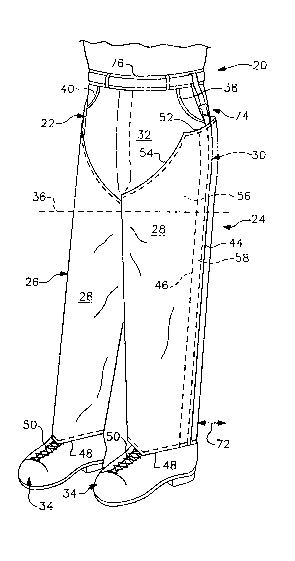
- Referring now to the drawing, FIG. 1 depicts
the lower body 20 of an individual wearing trousers 22
and leg warmers 24 and 26. Leg wanmers 24 and 26 are
constructed in accord with, and embody, the principles
of the pre~ent invention. The two leg warmers differ
only that they are cut in a right and left, mirror image
relationship.
Because of the close similarity of the two leg
warmers 24 and 26, only leg warmer 24 will be described
in detail herein. It is to be understood that this
description is equally applicable to leg warmer 26.
Referring again to the drawing, and more
` 15 specifically, to FIG. 2, leg wanmer 24 includes a wrap
around panel 28 and a closure system 30. Panel 28 is
cut and dimensioned to extend from the crotch 32 of the
wearer to the top of the wearer's footgear 34 and
thereby keep the wearer's entire leg warm. It i8 to be
noted, in this respect, that a jacket or other outer
garment (not shown) will normally be worn with leg
-warmer 24. This garment will typically extend down to
the level indicated by horizontal, dotted line 36 in
FIG. 1 to keep all of the wearer's body above leg
warmer 24 covered. The illustrated cut of leg warmer 24
also allows the individual wearing the leg warmer to
easily reach into the front pockets 38 and 40 and the
back pockets of trousers 22. One of these back pockets
is illustrated in each of FIGS. 3-7 and identified by
reference character 42.
Referring back to FIG. 2. wrap around leg
warmer panel 28 has vertically extendins side edges 44
and 46, a square cut bottcm end 48 designed to fit
2~7~
-10-
against the top 50 of the wearer's boots or shoes 34 as
shown in FIG. 1, and a top or upper end 52 with a
scallop 54 which accommodates the wearer's crotch 32 and
seat 55.
The wrap around panel 28 of leg warmer 24 may
be of single or multi-ply construction. The single ply
-- or at least one ply of a multi-ply panei -- is
fabricated from a material capable of providing thermal
insulation. Many such materials are commercially
available, and any suitable one of these may be
employed. The main requirements are that the selected
material provide adequate thermal insulation and that it
-- along with all other plys of a multi-ply panel -- be
very flexible. This is required so that the leg warmer
will not restrict or otherwise interfere with the
movement of those active wearers for which the leg
warmers of the present invention are primarily, although
not exclusively, intended. Also, the one ply of a
single ply panel or the outer ply of a multi-ply panel
can be made of a material which is impervious or
otherwise resistant to penetration by air, moisture,
snow, and other substances which might cause discomfort
~ to the ~earer.
- Leg warmer 24 is put on by wrapping its
panel 28 around the wearer's leg 56 with the vertically
extending edges 44 and 46 of the panel overlapped on the
outer side of the leg as shown in FIG. 1. The two
edges 44 and 46 of the panel are then joined together
over the entire span from the bottom 48 to the top 52 of
the leg warmer panel 28 by closure system 30 to provide
an essentially air, snow, and moisturetight joint 58
between these two edges of panel 28.
~7~
. --11--
Returning now to FIG. 2, the just-referred-to
closure system 30 of leg warmer 24 includes two,
elongated, pile-type fasteners 60 and 62. m ese
fasteners may be of the Velcro~ type.
Fasteners 60 and 62 are sewn or adhesively
bonded to the opposite sides 64 and 66 of panel 28 with
; the interengageable piles 68 and 70 of fasteners 60
and 62 exposed and apposite each other. Fastener 60
extends from the bottom 48 to top 52 of leg warmer 24
along edge 44. Cooperating fastener 62 similarly
extends from the bottom to the top of the leg warmer, in
this case along the opposite edge 46 of panel 28.
Once leg warmer 24 has been wrapped around the
leg 56 of the wearer in the manner discussed above, the
edge 44 of panel 28 is pressed against the edge 46 of
the panel, engaging the cooperating piles 68 and 70 of
- fasteners 60 and 62 to form the penetration-resistant
seam or joint 58 previously described.
Closure system 30 has the advantage that
fasteners 60 and 62 are easily connected together,
making the putting on of leg warmer 24 a simple and
easily accomplished task. ~his is not the case when the
~ leg warmer has to be pulled up over the wearer's
; trousers 22 as i8 necessary in many heretofore proposed
leg coverings, including most of those discussed above.
mis is especially true when trousers 22 are heavy and
bulky as they are for out-of-door use in cold weather.
Also, the two fasteners 60 and 62 can be adjusted
relatively to each other as suggested by arrow 72 in
FIG. 1 to vary the circumference of the leg warmer and
thereby make the leg warmer snugly fit the wearer's
leg 56 dt the bottom end 48 of the leg warmer.
ri
~ Q ~
--12--
A final, and also important, component of leg
warmer 24 is an adjustable suspender 74 for attaching
the leg warmer to the wearer's belt 76. This keeps the
leg warmer in place, even as the wearer engages in
strenuous activity.
Suspender 74 is of conventional construction
and will therefore not be described in any great detail
herein. Briefly, however, and as is best shown in
FIG. 2, suspender 74 includes: (1) a strap 78 sewn or
~o otherwise fastened to the top end 52 of leg warmer
panel 28 adjacent edge 44, (2) a clasp element 80 fixed
to strap 78, (3) a second strap 82 similarly attached to
the top end 52 of panel 28 adjacent edge 46, and (4) a
cooperating clasp element 84 through which strap 82 can
be threaded to increase and decrease the strap length
and, therefore, the length of suspender 74. Once the
leg warmer has been put on, strap 82 is threaded around
the wearer's belt 76 and clasp element 84 then hooked to
clasp element 80 (see FIG. 1) to complete the donning of
leg warmer 24.
Leg warmer 24 is taken off by reversinq the
just-described process, viz., by unhooking suspender 74,
pulling fastener 60 loose from cooperating fastener 62,
and then removing the leg warmer.
An identical procedure is employed to put on
and take off cooperating leg warmer 26.
The detailed description and discussion which
follows is devoted primarily to other embodiments of the
present invention. To a large extent, these resemble
the leg warmers 24 and 26 illustrated in FIGS. 1 and 2
and discussed above. To the extent that this true, the
same reference characters have been employed to identify
like components of the several leg warmers.
"
2~7~
-13-
Returning then to the drawing, FIGS. 3 and 4
depict a leg warmer 90 which differs from leg warmers 24
and 26 primarily in the ~ype of closure system it
employs. The closure system of leg warmer 90 is
s identified by reference character 92. It includes a
zipper-type fastener 94 and a pile-type fastener 98.
Fastener 94 extends upwardly from ~he bottom end 48 of
leg warmer panel 100. Fastener 98 is located above
fastener 94 and extends from it to the top end 52 of the
leg warmer panel.
Zipper-type fastener 94 is of conventional
construction. It has two cooperating rows 94a and 94b
of interengageable teeth and a pair of lower and upper
slides or sliders 94c and 94d for engaging and releasing
- 15 those teeth. As can be seen by comparing FIGS. 3 and 4,
the two rows 94a and 94b of zipper teeth are engaged to
join the two edges 44 and 46 of leg warmer 90 together
by moving lower slide 94c in a downward direction and by
moving upper slide 94d in the opposite direction.
Conversely, by moving slide 94d in a downward direction,
a gap 102 of selected length can be left between the two
edges 44 ahd 46 of leg warmer panel 100. That
ventilates leg warmer 90 as indicated by arrows 104 in
FIG. 4.
AS shown in FIG. 6, which depicts a third leg
TN1
warmer 105 with a zipper-type fastener 94, a second
ventilation gap 106 between leg warmer edges 44 and 46
can be provided by displacing zipper slide 94c in an
upward direction. mlS affords ventilation in the area
and in the pattern suggested by arrows 108 in FIG. 6 in
addition to, or in place of ventilation, as indicated by
arrows 104.
,,,
.... . .. - .
. ,
- 2~37~
-14-
r~
The dual zipper slides 94c and 94d allow the
ventilation gap 102 (or gaps 102 and 106) to be provided
without the leg warmer 90 becoming loose because the
edges 44 and 46 of the leg warmer remain joined at the
top and bottom ends 43 and 52 of the leg warmer and over
the major part of its length.
Referring again to FIG. 4, the pile-type
fa6tener 98 is employed in leg warmer 90 to make it
easier to start and close zipper-type fastener 94 (this
r~quires that the two edges 44 and 46 of the leg wanmer
panel 100 be brought together and the apposite ends of
the two interengageable zipper teeth rows 94a and 94b
aligned). Pile-type fastener 98 is connected up first
-~ to hold leg warmer 90 in place after panel 100 is
- 15 wrapped around the wearer's leg with the two rows 94
and 94b aligned and the wearer's hands free. It
includes cooperating, typically like configured and
dimensioned, fastener elements which are patches 110
and 112 of pile-type fastener material. Fastener
element 110 extends from the upper end 114 of zipper 94
to the top end 52 of leg warmer 90. It is sewn,
adhesively bonded, or otherwise attached to leg warmer
panel 100 adjacent the edge 44 of that panel.
ffle cooperating fastener element 112 is
similarly fixed to a flap 116 which is joined to or
integral with leg warmer panel 100 and is ex endable or
displaceable into overlying relationship with fastener
element llO. Fastener element 112 is affixed to that
side of flap 116 facing fastener element 110.
merefore, by pressing flap 116 against the wearer's
leg 56 after the leg warmer 90 has been wrapped around
the wearer's leg, the two fastener elements can be
2~7i~3
-15- -
connected or engaged to hold leg warmer 90 in place in
the manner and for the purposes just described.
m e panel 100 of leg warmer 90 has a three-ply
construction which is shown in FIG. 9. ~11 three
5 plys 118, 120, and 122 are of flexible materials which
will not limit or interfere with the wearer's movement.
Outer ply 118 is preferably wear-resistant and typically
a material which will offer resistance to penetration by
cold air and moisture or one which can be treated to
give it those properties. Central ply 120 is selected
for its thermal insulating capabilities, and inner
ply 122 is typically chosen for its ability to protect
- thermal insulation layer 120 while affording comfort to
the wearer.
It was pointed out above that leg warmers of
the character described herein may also have a closure
system which allows the lower end of the leg warmer to
be snugly fitted to the wearer's legs, thereby excluding
drafts, moisture, snow, etc. A closure system with this
capability as well as those of the closure system 92
illustrated in FIGS. 3 and 4 and just described is
employed in the leg warmer 105 illustrated in FIGS. 5
and 6. The closure system is identified in these
figures, to which reference is now made, by reference
character 128. r~
In closure system 128, a shorter zipper 94 is
employed so that the lower end 130 of the zipper will
lie above the bottom end 48 of leg warmer 105. Beneath
zipper 94 in this embodiment of the invention is a
second, pile-type fastener 132. This fastener is
employed in a manner akin to that discussed above in
; conjunction with leg warmer 24 to snugly fit the bottom
end 48 of leg warmer 105 to the wearer's leg 56.
2~3773~
As can be seen from FIG. 6, fastener 132
includes two cooperating elemen~s 134 and 136, each an
elongated, vertically oriented strip or rectangle of
-` pile-type fastener material extending from the lower
s end 130 of zipper-type fastener 94 to the bottom 48 of
leg warmer 105. One fastener element 134 is affixed to
- the wrap around panel 138 of leg warmer 105 adjacent
vertical edge 44 of the panel. Joined to, or integral
with, panel 138 at the bottom end thereof and extending
laterally from the cooperating, vertical edge 46 of the
panel is a flap 140 dimensioned and configured to
overlie fastener element 134. The second fastener
element 136 is attached to that side of flap 140 facing
fastener element in a comparable vertical orientation.
Consequently, as indicated by doubled-headed arrow 142
in FIG. 6, fast2ner element 136 can be displaced with
respect to fastener element 134 to adjust the
circumference of leg warmer 105 at its bottom end 48 and
thereby provide the desired snug fit with the leg 56 of
the wearer.
As is shown in FIG. 10, a two-ply construction
- is employed in the panel 138 of leg warmer 105. The
outer ply 144 is again preferably selected for its
resistance to wear and/or moisture, ~now, and wind. A
primary consideration in selecting the material for
inner ply 146 is thermal insulation.
-~ Yet another leg warmer embodying the
principles of the present invention is depicted in
FIG. 7 and identified by reference character 150. This
leg warmer employs a closure system 152 which is like
the closure system 128 illustrated in FIGS. 5 and 6 and
just discussed except that the upper, pile-type
fastener 98 is not employed; i.e., only the zipper-type
2~37~3~
-17-
fastener 94 and lower, snug fit facilitating, pile-type
fastener 132 are utilized. Also, the length of
fastener 94 is increased so that fastener will extend
from pile-type fastener 132 to the top end 52 of leg
warmer 150.
Leg warmer 150 has the advantage of being
simpler than leg warmer 105 and, consequently, less
expensive to produce.
FIGS. 8 and 8A show that the use of a
pile-type fastener as depicted in FIGS. 3-6 as an aid to
the putting on of leg warmers embodying the principles
of the present invention is not essential. Other types
of fasteners can instead be employed, if desired. For
example, the leg warmer 158 illustrated in the
just-mentioned figures employs snap-type fasteners 160
and 162. Each of these fasteners includes: (1) a male
- fastener element 164 attached to the wrap around
panel 166 of the leg warmer adjacent the edge 44 of that
~ panel and at the top end 52 thereof; and (2) a
; 20 cooperating, female fastener element 166 attached to,
and extending through, a flap 116 at the upper end of
the leg warmer panel (flap 116 is described above and
also illustrated in FIGS. 3-6).
The invention may be embodied in forms other
than that disclosed above without departing from the
spirit or essential characteristics of the invention.
me present embodiments are therefore to be considered
in all respects as illustrative and not restrictive, the
scope of the invention being indicated by the appended
claims rather than by the foregoing description; and all
changes which come within the meaning and range of
e~uivalency of the claims are therefore intended to be
embraced therein.