Language selection

Search

Patent 2038063 Summary

Third-party information liability

Some of the information on this Web page has been provided by external sources. The Government of Canada is not responsible for the accuracy, reliability or currency of the information supplied by external sources. Users wishing to rely upon this information should consult directly with the source of the information. Content provided by external sources is not subject to official languages, privacy and accessibility requirements.

Claims and Abstract availability

Any discrepancies in the text and image of the Claims and Abstract are due to differing posting times. Text of the Claims and Abstract are posted:

  • At the time the application is open to public inspection;
  • At the time of issue of the patent (grant).
(12) Patent: (11) CA 2038063
(54) English Title: MONITORING SYSTEM FOR STEP-TYPE SWITCHING TRANSFORMER
(54) French Title: SYSTEME DE SURVEILLANCE POUR TRANSFORMATEUR DE COMMUTATION A GRADINS
Status: Expired and beyond the Period of Reversal
Bibliographic Data
(51) International Patent Classification (IPC):
  • H02P 13/06 (2006.01)
  • H02H 07/055 (2006.01)
(72) Inventors :
  • DOHNAL, DIETER (Germany)
  • KUGLER, KURT (Germany)
(73) Owners :
  • MASCHINENFABRIK REINHAUSEN GMBH
(71) Applicants :
  • MASCHINENFABRIK REINHAUSEN GMBH (Germany)
(74) Agent: NORTON ROSE FULBRIGHT CANADA LLP/S.E.N.C.R.L., S.R.L.
(74) Associate agent:
(45) Issued: 1999-12-07
(22) Filed Date: 1991-03-12
(41) Open to Public Inspection: 1991-09-22
Examination requested: 1997-02-10
Availability of licence: N/A
Dedicated to the Public: N/A
(25) Language of filing: English

Patent Cooperation Treaty (PCT): No

(30) Application Priority Data:
Application No. Country/Territory Date
P 40 09 038.8 (Germany) 1990-03-21

Abstracts

English Abstract


A multiphase stepping transformer wherein a closed vacuum
interrupter at each phase is opened before a respective stepping
switch is advanced is controlled by continuously monitoring current
flow through the interrupters. Before the interrupters are opened an
error signal is generated unless all of the monitored current flows
lie to one side of a predetermined threshold. After the interrupters
are opened an error signal is generated if current flow is detected
through any of the interrupters. Advance of the stepping switches is
blocked on generation of any error signal. The apparatus includes for
each interrupter a respective current detector, a light-emitting diode
energized by the respective detector, a light receiver associated with
each diode, and a light-transmitting cable connecting each diode with
the respective receiver.


Claims

Note: Claims are shown in the official language in which they were submitted.

the embodiments of the invention in which an exclusive
property or privilege is claimed or defined are as follows:
1. A method of controlling a multiphase stepping transformer
wherein a closed vacuum interrupter at each phase is opened before
a respective stepping switch is advanced, the method comprising the
steps of:
continuously monitoring current flow through the
interrupters;
in a first period before the interrupters are opened an
error signal is generated unless all of the monitored current flows
lie to one side of a predetermined threshold;
in a second period after the interrupters are opened an
error signal is generated if current flow is detected through any of
the interrupters; and
blocking advance of the stepping switches on generation of
any error signal.
-7-

2. An apparatus for controlling a multiphase stepping
transformer wherein a closed vacuum interrupter at each phase is
opened before a respective stepping switch is advanced, the apparatus
comprising:
sensor means including respective detectors associated with
the interrupters for continuously monitoring current flow through the
interrupters; and
control means connected to the switches for blocking advance
of the stepping switches when
in a first period before the interrupters are opened an
error signal is generated unless all of the monitored
current flows lie to one side of a predetermined
threshold, and
in a second period after the interrupters are opened an
error signal is generated if current flow is
detested through any c>f the interrupters.
3. The apparatus defined in claim 2 wherein the sensor
means includes far each interrupter:
a respective current detector,
a light-emitting diode energized by the respective
detector,
a light receiver associated with each diode, and
a light-transmitting cable connecting each diode with
the respective receiver.
4. The apparatus defined in claim 3 wherein each cable is
integral with the respective diode and receiver.
-8-

5. The apparatus defined in claim 2 wherein the control
means includes
respective switches controlling the phases.
6. The apparatus defined in claim 5 wherein the switches
are reed switches coupled to the stepping switches.
7. The apparatus defined in claim 2 wherein the detectors
are saturation-type current detectors with built-in limiters.
8. The apparatus defined in claim 7 wherein each detector
is mounted directly on the respective interrupter.
9. The apparatus defined in claim 2 wherein the control
means includes bistable relays tripped by the error signals.
-9-

Description

Note: Descriptions are shown in the official language in which they were submitted.


MONITORING SYSTEM FOR STEP-TYPE SWITCHING TRANSFORMER
SPECIFICATION
Field of the Invention
The present invention relates to a step-type switching
transformer. More particularly 'this invention concerns a method of
and apparatus for monitoring the operation of the stepping switches of
such a transformer.
Brief Description of the Drawing
The above and other objects, features, and advantages will
become more readily apparent from the following, reference being made
to the accompanying drawing in which:
Fig. 1 is a schematic diagram of a prior-art system;
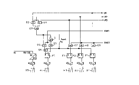
Fig. 2 is a schematic diagram of the system according to
this invention; and
Fig. 3 is a block diagram illustrating the evaluating
circuit of the system of this invention.
Background of the Invention
In stepping-switch systems for transformers wherein instead
of the standard contacts used for switching the load a vacuum-type
switch is employed, a monitoring system is reguired to prevent acci-
dents when the vacuum switch does not open soon enough or at all when
stepping to the next position. When the vacuum switch does not open
the switching has to take place while under load sa 'that substantial
- 1 -

arcing can be counted on. In a high-power system such arcing can
destroy the stepping switches.
Such a monitoring system is sold by ~jdR Reinbeusen Manufac-
turing as a Type UST load tap changer. Fig. 1 shows the switching
circuit for a single phase. Sere parallel to current converters CT1'
and CT2' there are respective mechanical switches P2 and P3. A
solenoid S connected across them detects the presence of any current
flow in the movable contacts P1 and P4 during what is supposed to be
load-free switching across contacts 3 through 12 of a transformer
winding M having a reversing switch A, B. The switch P2 is controlled
such that it opens after a vacuum interrupter V has taken over the
current flow from a bypass contact and before the contact P1 opens and
closes after P1 closes again. The switch P3 opens after the vacuum
interrupter V has taken over the load and before the selector contact
P4 opens and closes after P4 closes again but before vacuum inter-
rupter V has closed again.
If the vacuum interrupter V fails so that during a switching
operation one of the switches P1 or P4 continues to conduct currant,
the solenoid S is actuated. This solenoid S is normally energized to
hold open a mechanical latch that, when closed, prevents movement of
the stepping switch.
Such an arrangement is complex and has numerous parts which
can fail. In addition the monitoring and control system is provided
in the oil-filled stepping switch so that this device must be taken
apart to make any adjustments or repairs, and any such servicing
requires that the oil be drained and subsequently refilled.

~3~fl~3
Objects of the Invention
It is therefore an object of the presemt invention to
provide an improved method of and apparatus for monitoring operation
of a stepping switch of a step transformer.
Another object is the provision of such an improved method
of and apparatus for monitoring operation of a stepping switch of a
step transformer which overcomes the above-given disadvantages, that
is which is relatively simple, which can be provided outside the oil-
filled switching equipment, and which can be easily reset.
Summary of the Invention
According to this invention a multiphase stepping trans-
former wherein a closed vacuum interrupter at each phase is opened
before a respective stepping switch is advanced is controlled by
continuously monitoring current flow through the interrupters. In a
first period before the interrupters are opened an error signal is
generated unless all of the monitored current flows lie to one side of
a predetermined threshold. In a second period after the interrupters
are opened an error signal is generated if current flow is detected
'through any ~f the interrupters. Advance of the stepping switches is
blocked on generation of any error signal.
Before the interrupters are opened they should all be either
conducting or not, depending on whether the transformer is under load
or not. If one is not conducting while 'the other others are or vice
versa, this is proof that something is wrong. once -they have been
actuated so that they all should be opened, if current is flowing
through any of them, this fact is once again proof that something is

~0~~~~'~
wrong and stepping of the switches is blocked by a mechanical latch
operated by the controller.
The apparatus according to this invention includes for each
interrupter a respective current detector, a light-emitting diode
energized by the respective detector, a light receiver associated with
each diode, and a light-transmitting cable connecting each diode with
the respective receiver. This allows everything but the transmitter
and the detector to be mounted outside the housing of the transformer
equipment, where it can be serviced and reset easily. Each cable is
integral with the respective diode and receiver so it can pass through
the oil bath with no problems.
The controller of the instant invention also aim 2 wherein
the control means includes respective switches controlling the respec-
tive different periods before and after the interrupters are opened.
These switches are reed switches coupled to the stepping switches.
The detectors according to this invention are saturation-
type current detectors with built-in limiiters and each detector is
mounted directly on the respective interrupter.
The controller further has bistable relays tripped by the
error signals and normally operating a mechanical latch that locks
advance of the stepping switches until the problem is cleared up.
S~eC:ific T3escri~tion
As seen in Fig. 2 the current flows through the vacuum
interrupters V1, V2, V3, which are each associated with a respective
phase of the load switch, are each monitored by a respective satura-
tion current converter CT1, CT2, CT3 having a built-in limiter. Each
such converter CT1, CT2, and CT3 can energize a respective light-
emitting diode acting as a transmitter LE1, LE2, LE3 connected via
- 4 -

~o~~o~
fiber-optic cables C1, C2, and C3 to respective light receivers LR1,
LR2, and LR3, the latter being located well outside the equipment.
The converters CT1, CT2, arid CT3 and limiting circuitry are mounted
right on the respective interrupters V1, V2, and V3, being molded
right into their housings and are set up to respond when a current of
more than 10A flows through them. Thus the receivers LR1, LR2, and
LR3 report when there is any significant current moving in the respec-
tive interrupters V1, V2, and V3. The cables C1, C2, and C3 can be
single- or multifilament fiber-optic units with integral transmitters
and receivers and the receivers LR1, LR2, and LR3 can have standard
TTL outputs.
This system operates with two main verifications of current
flow in the interrupters V1, V2, and V3. Two reed switches RSW1 and
RSW2 operated directly by the shaft on which the poles of the stepping
switches are carried are actuated to operate one of two logic networks
1 or 2 to determine if any of the interrupters V1, V2, or V3 has
failed.
Switch R5W1 is actuated to start the first monitoring step
in which the circuit 1 compares the outputs of all three receivers
LR1, LR2, and LR3 and produces an error signal a~t K4 if they are not
all the same. This error signal can be used to block switching.
The second monitoring step is triggered by actuation of the
switch RSW2 after the interrupters should all be open-circuited but
before the load-free movement of the respective step switches. Tf
after this second monitoring step is initiated, the circuit 2 deter-
mines that there is current flow in any of the interrupters V1, V2, or
V3, it produces an error signal K1, K2, or K3 depending on which one
is conducting.
Fig. 3 shows a circuit which can carry out the functions of
both circuits 1 and 2. The inputs from the receivers LR1, LR2, and

hR3 are fed to NOR gates G1 and G2 whose outputs are fed to an AND
gate G8 whose output is fed directly to another AND gate G4 and
through an invertor I to another AND gate G5. The AND gates G4 and G5
are also fed inputs from the switch RSW1 so they only produce an
output when both inputs are energized. The output of the AND gate G4
goes through an OR gate G6 to a flip flop F4 that produces the output
K4. The other outputs K1, K2, and K3 are produced by flip flops F1,
F2, and F2 each getting an reset input R from the reset switch like
the NOR gate G6 and from an AND gate G7, G8, and G9 each having one
input from the respective receiver LR1, LR2, and LR3 and another input
from the switch RSW2. The output K~ thus reports a disturbance at the
time the switch RSW1 is momentarily closed unless all three inputs
indicate current present or all three indicate no current present. On
the other hand the outputs K1, K2, or K3 are produced when any of the
vacuum interrupters fails when the switch RSW2 is momentarily closed.
Histable relays R1 through R5 can be set by the outputs K1
through K4, and even K5 which indicates ~pawer on, and these relays can
be keyed so only authorized personnel cam reset them. When flip-flops
are used as in Fig. 3, the reset switch should be similarly protected.
- 6 -

Representative Drawing
A single figure which represents the drawing illustrating the invention.
Administrative Status

2024-08-01:As part of the Next Generation Patents (NGP) transition, the Canadian Patents Database (CPD) now contains a more detailed Event History, which replicates the Event Log of our new back-office solution.

Please note that "Inactive:" events refers to events no longer in use in our new back-office solution.

For a clearer understanding of the status of the application/patent presented on this page, the site Disclaimer , as well as the definitions for Patent , Event History , Maintenance Fee  and Payment History  should be consulted.

Event History

Description Date
Inactive: Reversal of expired status 2012-12-02
Time Limit for Reversal Expired 2011-03-12
Letter Sent 2010-03-12
Inactive: IPC from MCD 2006-03-11
Grant by Issuance 1999-12-07
Inactive: Cover page published 1999-12-06
Pre-grant 1999-09-03
Inactive: Final fee received 1999-09-03
Notice of Allowance is Issued 1999-07-29
Letter Sent 1999-07-29
Notice of Allowance is Issued 1999-07-29
Inactive: Approved for allowance (AFA) 1999-06-29
Inactive: Adhoc Request Documented 1998-12-15
Inactive: IPC removed 1998-12-09
Inactive: First IPC assigned 1998-12-09
Inactive: IPC assigned 1998-12-09
Inactive: Single transfer 1998-10-09
Inactive: Status info is complete as of Log entry date 1997-11-25
Amendment Received - Voluntary Amendment 1997-11-25
Inactive: Application prosecuted on TS as of Log entry date 1997-11-25
All Requirements for Examination Determined Compliant 1997-02-10
Request for Examination Requirements Determined Compliant 1997-02-10
Application Published (Open to Public Inspection) 1991-09-22

Abandonment History

There is no abandonment history.

Maintenance Fee

The last payment was received on 1999-11-16

Note : If the full payment has not been received on or before the date indicated, a further fee may be required which may be one of the following

  • the reinstatement fee;
  • the late payment fee; or
  • additional fee to reverse deemed expiry.

Patent fees are adjusted on the 1st of January every year. The amounts above are the current amounts if received by December 31 of the current year.
Please refer to the CIPO Patent Fees web page to see all current fee amounts.

Owners on Record

Note: Records showing the ownership history in alphabetical order.

Current Owners on Record
MASCHINENFABRIK REINHAUSEN GMBH
Past Owners on Record
DIETER DOHNAL
KURT KUGLER
Past Owners that do not appear in the "Owners on Record" listing will appear in other documentation within the application.
Documents

To view selected files, please enter reCAPTCHA code :


To view images, click a link in the Document Description column (Temporarily unavailable). To download the documents, select one or more checkboxes in the first column and then click the "Download Selected in PDF format (Zip Archive)" or the "Download Selected as Single PDF" button.

List of published and non-published patent-specific documents on the CPD .

If you have any difficulty accessing content, you can call the Client Service Centre at 1-866-997-1936 or send them an e-mail at CIPO Client Service Centre.

({010=All Documents, 020=As Filed, 030=As Open to Public Inspection, 040=At Issuance, 050=Examination, 060=Incoming Correspondence, 070=Miscellaneous, 080=Outgoing Correspondence, 090=Payment})


Document
Description 
Date
(yyyy-mm-dd) 
Number of pages   Size of Image (KB) 
Abstract 1993-12-20 1 23
Claims 1993-12-20 3 67
Drawings 1993-12-20 3 56
Description 1993-12-20 6 234
Representative drawing 1999-12-01 1 8
Reminder - Request for Examination 1997-11-11 1 117
Commissioner's Notice - Application Found Allowable 1999-07-28 1 163
Maintenance Fee Notice 2010-04-25 1 170
Correspondence 1999-09-02 1 47
Fees 1997-02-17 1 64
Fees 1995-03-01 1 64
Fees 1993-12-08 1 101
Fees 1996-02-27 1 58
Fees 1993-01-04 1 48