Language selection

Search

Patent 2038124 Summary

Third-party information liability

Some of the information on this Web page has been provided by external sources. The Government of Canada is not responsible for the accuracy, reliability or currency of the information supplied by external sources. Users wishing to rely upon this information should consult directly with the source of the information. Content provided by external sources is not subject to official languages, privacy and accessibility requirements.

Claims and Abstract availability

Any discrepancies in the text and image of the Claims and Abstract are due to differing posting times. Text of the Claims and Abstract are posted:

  • At the time the application is open to public inspection;
  • At the time of issue of the patent (grant).
(12) Patent Application: (11) CA 2038124
(54) English Title: COLOR CHANGE VALVE ASSEMBLY
(54) French Title: GARNITURE D'ETANCHEITE POUR VANNE DE CHANGEMENT DE COULEUR
Status: Deemed Abandoned and Beyond the Period of Reinstatement - Pending Response to Notice of Disregarded Communication
Bibliographic Data
(51) International Patent Classification (IPC):
  • F16K 41/00 (2006.01)
(72) Inventors :
  • MEDLOCK, D. WILLIAM (United States of America)
  • ALEXANDER, KEVIN L. (United States of America)
(73) Owners :
  • RANSBURG CORPORATION
(71) Applicants :
  • RANSBURG CORPORATION (United States of America)
(74) Agent: SMART & BIGGAR LP
(74) Associate agent:
(45) Issued:
(22) Filed Date: 1991-03-12
(41) Open to Public Inspection: 1991-09-24
Availability of licence: N/A
Dedicated to the Public: N/A
(25) Language of filing: English

Patent Cooperation Treaty (PCT): No

(30) Application Priority Data:
Application No. Country/Territory Date
07/498,018 (United States of America) 1990-03-23

Abstracts

English Abstract


Abstract of the Disclosure
A seal assembly for sealing a valve needle
having a generally circular cross section transverse to
its longitudinal axis. The needle is situated inside a
valve assembly including a housing having a longitudinal
axis. The needle controls flow of a fluid from a fluid
supply line to a fluid outlet passage. The seal
assembly comprises a seal positioner including a
cylindrical body portion surrounding the needle and
having a first end, a second end, and an inner side wall
having a cross section larger than the cross section of
the needle to define a space between the inner side wall
and the needle. The seal positioner also includes a
partition for coupling the body portion to the needle to
align the body portion concentrically with the needle
and to maintain the concentric alignment upon
misalignment of the longitudinal axis of the needle and
the longitudinal axis of the valve assembly. The
partition provides first and second sealing regions
spaced longitudinally along the needle. A first seal in
the first sealing region extends perimetrally around the
needle and contacts a first portion of it. A second
seal in the second sealing region extends perimetrally
around the needle and contacts a second portion of it.


Claims

Note: Claims are shown in the official language in which they were submitted.

-11-
Claims:
1. A seal assembly for sealing a valve needle
situated inside a valve assembly along a longitudinal
axis of the valve assembly, the valve needle controlling
flow of a fluid from a fluid supply line to a fluid
outlet passage, the seal assembly comprising
first means for contacting a first portion of
the needle to provide a first seal which extends
perimetrally around the needle,
second means for contacting a second portion of
the needle spaced longitudinally on the needle from the
first portion to provide a second seal which extends
perimetrally around the needle, and
means for positioning the first and second
means against the needle, the positioning means
including means for maintaining the first and second
means in sealing contact with the perimeter of the
needle in their respective longitudinally spaced
orientations, the positioning means permitting movement
of the needle therethrough as the needle moves relative
to the valve assembly.
2. The assembly of claim 1 wherein the needle
has a generally circular cross section transverse to its
longitudinal extent, the positioning means includes a
cylindrical body portion surrounding the needle, the
body portion has an inner perimeter larger than the
cross section of the needle to define a space between
the body portion and the needle, and the body portion
further includes a partition extending radially inwardly
from the inner perimeter of the body portion for

-12-
slidably receiving the needle, the partition providing
first and second sealing regions spaced longitudinally
along the needle for receiving the first and second
means, respectively.
3. The assembly of claim 2 wherein the first
means includes a somewhat U-shaped cup situated in the
first sealing region and opening axially of the needle.
4. The assembly of claim 2 wherein the second
means includes an O-ring situated in the second sealing
region.
5. The assembly of claim 1 wherein the
positioning means includes a seal positioner having a
somewhat H-shaped cross section to define first and
second sealing regions for receiving the first and
second means, respectively.
6. Assembly of claim 5 wherein the seal
positioner includes a body portion having an inner side
wall surrounding the needle, means defining a partition
extending radially inwardly toward the needle from the
inner side wall, and a passageway defined in the
partition for slidably receiving the needle, the
partition dividing the space within the inner side wall
of the seal positioner into first and second sealing
regions spaced axially along the needle, the first means
being positioned in the first sealing region and the
second means being positioned in the second sealing
region.
7. The assembly of claim 6 wherein the inner
side wall of the body portion holds the first and second
means in sealing engagement with the needle as the
needle moves along its axis as the valve operates.

-13-
8. The assembly of claim 7 wherein the first
means includes a somewhat U-shaped cup situated in the
first sealing region and the second means includes an
O-ring situated in the second sealing region.
9. An assembly for sealing a valve needle
having a generally circular cross section transverse to
its longitudinal axis, the valve needle being situated
inside a valve body, the valve needle controlling flow
of a fluid from a fluid supply passage in the valve body
to a fluid outlet passage in the valve body, the seal
assembly comprising a cylindrical body portion including
an outer side wall and an inner side wall, a web
extending radially inwardly from the inner side wall,
the web including a central passageway extending
longitudinally of the needle through which the needle
moves longitudinally, the needle being slidably received
in the central passageway formed in the web to align the
cylindrical body portion concentrically with the needle,
the inner side wall defining a space radially inwardly
therefrom adjacent the web, and means situated inside
the space and extending perimetrally around the needle
for sealing the needle to prevent passage of fluid from
the fluid supply passage beyond the sealing means.
10. The assembly of claim 9 wherein the
sealing means includes first means for contacting a
first portion of the needle to provide a first seal
which extends perimetrally around the needle and second
means for contacting a second portion of the needle
spaced longitudinally on the needle from the first
portion to provide a second seal which extends
perimetrally around the needle.

-14-
11. The assembly of claim 10 wherein the web
defines first and second sealing regions in the space
between inner side wall and the needle, the first and
second sealing regions being spaced longitudinally along
the needle for receiving the first and second means,
respectively.
12. The assembly of claim 11 wherein the first
means includes a somewhat U-shaped cup situated inside
the first sealing region, the inner side wall of the
body portion holding the U-shaped cup in sealing
engagement with the needle as the needle moves along its
longitudinal axis as the valve operates and upon
misalignment of the needle and the valve assembly.
13. The assembly of claim 11 wherein the
second means includes an O-ring situated inside the
second sealing region, the inner side wall of the body
portion holding the O-ring in sealing engagement with
the needle as the needle moves along its longitudinal
axis as the valve operates and upon misalignment of the
needle and the valve assembly.
14. A seal assembly for sealing a valve needle
having a generally circular cross section transverse to
its longitudinal axis, the needle being situated inside
a valve assembly including a housing having longitudinal
axis therethrough, the needle controlling flow of a
fluid from a fluid supply line to a fluid outlet
passage, the seal assembly comprising
a seal positioner including a cylindrical body
portion surrounding the needle, the cylindrical body
portion having a first end, a second end, and an inner

-15-
side wall having a cross section larger than the cross
section of the needle to define a space between the
inner side wall and the needle, the seal positioner also
including means for coupling the body portion to the
needle to align the body portion concentrically with the
needle and to maintain the concentric alignment upon
misalignment of the longitudinal axis of the needle and
the longitudinal axis of the valve assembly, the
coupling means providing first and second sealing
regions spaced longitudinally along the needle, and
first means situated in the first sealing
region for contacting a first portion of the needle to
provide a first seal which extends perimetrally around
the needle, and
second means situated in the second sealing
region for contacting a second portion of the needle
spaced longitudinally from the first portion to provide
a second seal which extends perimetrally around the
needle.
15. The seal assembly of claim 14 wherein the
coupling means includes a partition extending radially
inwardly toward the needle from the inner side wall, and
a passageway defined in the partition for slidably
receiving the needle, the partition dividing the space
between the inner side wall of the seal positioner and
the needle into the first and second sealing regions
spaced longitudinally along the needle.
16. The seal assembly of claim 15 wherein the
inner side wall of the body portion holds the first and
second means in sealing engagement with the needle as

-16-
the needle moves along the axis of the valve assembly as
the valve operates and upon misalignment of the needle
and the valve assembly.
17. The seal assembly of claim 16 wherein the
first means includes a somewhat U-shaped cup situated in
the first sealing region and the second means includes
an O-ring situated in the second sealing region.
5506p

Description

Note: Descriptions are shown in the official language in which they were submitted.


2~3~2~
--1--
COLOR CHANGE VALVE ASSEMBLY
Backaround and Summary of the Invention
The present invention relates to a valve needle
seal assembly. It finds particular utility inside a
paint valve assembly to provide a seal for a valve
needle which controls flow of paint from a supply line
to an outlet passage.
Conventional valve assemblies use packing seals
to seal a valve needle to prevent the passage of fluid
from a fluid supply line along the valve needle beyond
the packing seal. Conventional packing seals must be
compressed inside the valve assembly to hold the packing
seal in engagement with the valve needle. The packing
seal is typically compressed inside the valve assembly
by an adjustable packing nut. To prevent leakage of the
fluid along the needle beyond the packing seal, the
packing nut must be continually tightened or adjusted
throughout the life of the valve assembly. One problem
associated with conventional packing seals is that
concentricity of the valve needle and the packing seal
must be accurately controlled in order to prevent the
packing seal from leaking. Any misalignment of the
longitudinal axis of the valve needle and the
longitudinal axis of the valve assemb]y can cause the
packing seal to leak.
One object of the present invention is to
provide a seal assembly which moves or "floats" with the
valve needle so that the seal assembly remains
concentrically aligned with the valve needle regardless

2~3312~
of the alignment of the valve needle with the valve
assembly.
Another object of the present invention is to
eliminate the need for direct compression of the seal
assembly in order to seal the valve needle.
Yet another object of the present invention is
to eliminate the need to continually adjust the valve
assembly throughout the life of the valve assembly in
order to maintain the valve needle seal.
According to the present invention, a seal
assembly is provided for sealing a valve needle situated
inside a valve assembly along a longitudinal axis of the
valve assembly. The valve needle controls flow of a
fluid from a fluid supply line to a fluid outlet
lS passage. The seal assembly includes first means for
contacting a first portion of the needle to provide a
first seal which extends perimetrally around the
needle. The seal assembly also includes second means
for contacting a second portion of the needle spaced
longitudinally on thé needle from the first portion to
provide a second seal which extends perimetrally around
the needle. The seal assembly further includes means
for positioning the first and second sealing means
against the needle. The positioning means includes
means for maintaining the first and second sealing means
in sealing contact with the perimeter of the needle in
their respective longitudinally spaced orientations.
The positioning means permits movement of the needle
therethrough as the needle moves relative to the valve
assembly during operation of the valve.

2~3~124
The positioning means includes a seal
positioner having a somewhat H-shaped cross section to
define the first and second sealing regions for
receiving the first and second sealing means,
respectively. The seal positioner includes a body
portion having an inner side wall surrounding the needle
and a partition extending radially inwardly toward the
needle from the inner side wall. A passageway defined
in the partition slidably receives the needle. The
partition divides a space between the inner side wall
and the valve needle into first and second sealing
regions spaced axially along the needle. The first
sealing means is positioned in the first sealing region,
and the second sealing means is positioned in the second
sealing region. The inner side wall of the body portion
holds the first and second sealing means in sealing
engagement with the needle as the needle moves along its
axis as the valve operates. The seal positioner and the
valve needle remain in alignment without regard to the
alignment of the needle with a longitudinal axis of the
valve assembly to maintain contact between the valve
needle and the first and second sealing means.
Brief DescriDtion of the Drawinas
The invention may best be understood by
referring to the following description of the
accompanying drawings which illustrate the invention.
In the drawings:
Fig. l is a fragmentary sectional view of a
conventional packing seal used in prior art devices to
seal a valve needle;

~03~12~
--4--
Fig. 2 is a sectional view illustrating the
seal assembly of the present invention located inside a
valve assembly which is coupled to a manifold of a color
changer system;
Fig. 3 illustrates an enlarged sectional view
of a portion of Fig. 2 illustrating the seal assembly of
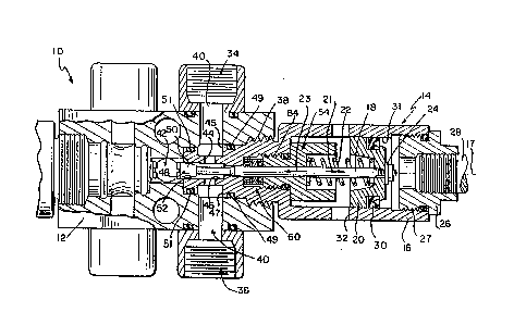
the present invention in detail; and
Fig. 4 illustrates an exploded sectional view
of the seal assembly illustrated in Fig. 3.
_etailed Description of the Drawinqs
A modular color changer system 10 illustrated
in Fig. 2 includes a segment of a manifold 12 and a
plurality of valve assemblies 14 coupled to the manifold
12, each by a threaded section 38. For puposes of
simplicity, only one such valve assembly is
illustrated. However, the arrangement of such
assemblies along a manifold is well known in the art.
Each valve assembly 14 includes a housing 16 and a valve
needle 18 situated inside the housing 16 for movement
longitudinally along an axis 17. A separate valve
assembly 14 is provided, for example, for each different
color of paint or type of fluid. Manifold 12 and valve
housing 16 are preferably made from solvent-resistant
resins. A seal between the housing 16 and the
manifold 12 is achieved by compression of housing 16
against the manifold 12 and by first and second O-ring
seals 49 and 51.
A reciprocating piston 20 located inside
housing 16 provides movement of valve needle lB along

2~3~12~
axis 17 to operate the valve. A spring 22 captured in a
spring cup provided by a seal retaininer 54 biases the
piston 20 in the direction of arrow 21 to maintain the
valve in a normally closed position. Valve needle 18 is
coupled to piston 20 by a suitable fastener 24. An end
cap 26 is threaded into the en~ of 27 of housing 16. A
compressed air supply line 28 is connected to end cap 26
to supply compressed air to move piston 20 in the
direction of arrow 23 when valve 14 is to be opened to
supply the fluid controlled thereby to manifold 12. A
seal ring 30 is provided between piston 20 and the
cylinder wall 31 of housing 16.
The various supplies of paint in color changer
system 10 must typically be continuously recirculated to
prevent, for example, the settlement of pigments out of
them. Manifold 12 includes an inlet port 34, an outlet
port 36, and a fluid circulation line 40 extending
between inlet port 34 and outlet port 36. When color
valve assembly 14 is threaded into manifold 12, an inlet
opening 45, a fluid passage 44, and an outlet opening 47
of housing 16 communicate with fluid circulation line
40. Fluid enters inlet port 34 from a remote paint
supply. As long as needle 18 is in its position
illustrated in Fig. 2, the fluid passes into fluid
circulation line 40, through fluid passage 44, through
outlet opening 47, and fluid circulation line 40 to
outlet port 36.
Manifold 12 includes a central passageway 42
extending through manifold 12. Central passageway 42
conducts paint from manifold 12 through a paint line

2~3~2~
coupled thereto (not shown) to a suitable spraying
apparatus (not shown) at a remote location. Valve
needle 18 includes a sealing head 48 having a tapered,
somewhat frustoconical side wall 50. Valve housing 16
includes a valve seat 52. When piston 20 is moved in
the direction of arrow 23, the tapered side wall 50
moves away from valve seat 52. This permits some of the
paint passing through the housing 16 to enter the
central passageway 42 of manifold 12 to supply paint to
the paint spraying apparatus (not shown) at the remote
location.
Upon removal of the compressed air signal at
line 28, spring 22 moves piston 20 in the direction of
arrow 21 to close the valve. This prevents fluid from
entering passageway 42, and all of the paint supplied at
port 34 recirculates as discussed above. Valve assembly
14 remains in this normally closed position until
another air pressure signal at line 28 causes movement
of valve needle 18 in the direction of arrow 23.
There are no recirculating fittings which
thread directly into the valve housing 16. This feature
permits rapid interchangeability of the valve
assemblies 14. The present invention enables the valve
assembly 14 to be removed from the manifold 12 without
the need to remove any fluid lines or fluid fittings
from valve housing 16. This permits faster replacement
or maintenance of valve assemblies 14 which reduces down
time for the color changer system 10, and therefore
increases productivity.
A visual indication of the open or closed
status of valve assembly 14 is provided through

~3~
apertures 32 provided in housing 16. Piston 20 is
typically a bright color so that the color can be seen
through apertures 32 when the valve is open. Valve
housing 16 preferably has a hexagonal cross sectional
shape to facilitate installation and removal of the
valve assembly 14.
As fluid recirculates from inlet port 34 to
outlet port 36, the fluid tends to move from
longitudinal aperture 46 along needle 18 in the
direction of arrow 21. Without proper sealing of valve
needle 18, fluid can pass beyond seal assembly 60 into
the main body of housing 16 to leak or clog the valve
assembly 14.
A conventional prior art assembly for sealing
the valve needle is shown in Fig. 1. The prior art
device uses a compressed Chevron-type packing 56 which
is compressed by an adjustable packing nut 55. To
prevent leakage of paint beyond the packing 56, the
packing nut 55 must be continuously tightened throughout
the life of the packing 56. During operation of the
prior art valve assembly, if the valve needle 18 becomes
misaligned in housing 16, the packing 56 can permit
paint to leak past packing 56 and into the body of
housing 16. Therefore, valve assembly 14 must be
replaced or cleaned. The valve assembly 14 of the
present invention includes a seal assembly 60 designed
to overcome the disadvantages of prior art packings 56.
The seal assembly 60 of the prevent invention
is best illustrated in Figs. 3 and 4. Seal assembly 60
includes a generally cylindrical body portion 6Z having

2~3~124
an outer side wall 64 and an inner side wall 66. Valve
needle 18 has a generally circular cross section. The
perimeter of inner side wall 66 is larger than the cross
section of the needle 18 to define a space between the
needle 18 and inner side wall 66 of body portion 62.
Body portion 62 includes a web or partition 68 extending
radially inwardly from inner side wall 66 of body
portion 62. Partition 68 is formed to include a central
passageway 70 extending longitudinally of the needle
18. Cylindrical body 62 and partition 68 define a seal
positioner having a somewhat H-shaped cross section.
The position of needle 18 is shown in phantom in Fig.
4. Partition 68 divides the space between inner side
wall 66 and needle 18 into a first sealing region 72 and
a second sealing region 74.
The seal assembly 60 includes a U-shaped cup
seal 76 which contacts a first portion of needle 18 to
provide a first seal which extends perimetrally around
the needle 18. Seal assembly 60 also includes an O-ring
seal 78 which contacts a second portion of the needle 18
spaced longitudinally along the needle 18 from the
U-shaped cup seal 76 to provide a second seal which
extends perimetrally around the needle 18. The U-shaped
cup 76 is situated in the first sealing region 72 and
the O-ring 78 is situated in the second sealing region
74.
Inner side wall 66 of body portion 62 engages
the U-shaped cup 76 and the O-ring 78 and holds these
two seals 76 and 78 in engagement with needle 18 as
needle 18 moves as the valve operates. The seal

2~3~24
assembly 60 moves or floats with the needle 18 in the
event of misalignment of the needle 18 with valve
assembly 14. This maintains a concentric alignment of
the cylindrical body portion 62 with the valve needle 18
to ensure that U-shaped cup seal 76 and the O-ring 78
maintain continuous contact with valve needle 18.
Passageway 70 formed in the seal assembly 60
slidably receives needle 18 to permit the needle 18 to
move along its longitudinal axis through the seal
assembly 60 to open and close the valve. Cylindrical
body portion 62 correctly positions and spaces seals
76 and 78 alony the needle 18 as the valve operates.
As best shown in Fig. 3, seal assembly 60
includes a first end 63 and a second end 65. Valve
housing 16 includes a seal retaining wall 80. Seal
retainer 59 is threaded into housing 16 at 84. An
O-ring 85 is provided between the threaded portion 84
and the body of seal retainer 54. Seal retainer 54
includes an end wall 82. O-ring seal 78 of seal
assembly 60 extends beyond the second end 65 of body
portion 62. End wall 82 of seal retainer 54 compresses
the O-ring 78 to hold the first end 63 of seal assembly
60 against retaining wall 80 of housing 16.
A small amount of clearance (about .002-.006
inch) is provided between needle 18 and inner wall 86 of
housing 16. This small amount of clearance is also
provided between needle 18 and inner wall 88 of seal
retainer 54. This clearance permits needle 18 to move
along its longitudinal axis during operation of the
valve.

2~3~
--10--
Seal assembly 60 seals and permits movement of
valve needle 18 while maintaining spacing between the
two seals 76 and 78. O-ring 78 and end wall 82 of seal
retainer 54 provide a further seal to prevent fluid
which might enter the space 90 between outer sidewall 64
of body portion 62 and housing 16 to pass between end
wall 82 and 0-ring 78.
The seal assembly 60 is designed to move or
float with needle 18 in the event of misalignment
between needle 18 and valve assembly 14. This provides
adequate sealing of needle 18 to prevent leakage of
paint beyond seal assembly 60. Misalignment can occur,
for example, due to manufacturing tolerances or during
operation of the valve.
Although the invention has been described in
detail with reference to a preferred embodiment,
variations and modifications exist within the scope and
spirit of the invention as described and defined in the
ollowing claims.

Representative Drawing
A single figure which represents the drawing illustrating the invention.
Administrative Status

2024-08-01:As part of the Next Generation Patents (NGP) transition, the Canadian Patents Database (CPD) now contains a more detailed Event History, which replicates the Event Log of our new back-office solution.

Please note that "Inactive:" events refers to events no longer in use in our new back-office solution.

For a clearer understanding of the status of the application/patent presented on this page, the site Disclaimer , as well as the definitions for Patent , Event History , Maintenance Fee  and Payment History  should be consulted.

Event History

Description Date
Time Limit for Reversal Expired 1994-09-13
Application Not Reinstated by Deadline 1994-09-13
Deemed Abandoned - Failure to Respond to Maintenance Fee Notice 1994-03-14
Inactive: Adhoc Request Documented 1994-03-14
Application Published (Open to Public Inspection) 1991-09-24

Abandonment History

Abandonment Date Reason Reinstatement Date
1994-03-14
Owners on Record

Note: Records showing the ownership history in alphabetical order.

Current Owners on Record
RANSBURG CORPORATION
Past Owners on Record
D. WILLIAM MEDLOCK
KEVIN L. ALEXANDER
Past Owners that do not appear in the "Owners on Record" listing will appear in other documentation within the application.
Documents

To view selected files, please enter reCAPTCHA code :


To view images, click a link in the Document Description column (Temporarily unavailable). To download the documents, select one or more checkboxes in the first column and then click the "Download Selected in PDF format (Zip Archive)" or the "Download Selected as Single PDF" button.

List of published and non-published patent-specific documents on the CPD .

If you have any difficulty accessing content, you can call the Client Service Centre at 1-866-997-1936 or send them an e-mail at CIPO Client Service Centre.

({010=All Documents, 020=As Filed, 030=As Open to Public Inspection, 040=At Issuance, 050=Examination, 060=Incoming Correspondence, 070=Miscellaneous, 080=Outgoing Correspondence, 090=Payment})


Document
Description 
Date
(yyyy-mm-dd) 
Number of pages   Size of Image (KB) 
Claims 1991-09-23 6 178
Abstract 1991-09-23 1 28
Drawings 1991-09-23 1 44
Descriptions 1991-09-23 10 318
Representative drawing 1999-07-29 1 25
Fees 1993-02-28 1 44