Note: Descriptions are shown in the official language in which they were submitted.
2 ~
Casa No .: CLEMN-Oû lA
;
GaS-PHASE P~OPA~E: FUE:L DE:LIV~3RY SYSTE2il -
~i~ld ~f ~h~ InYention
The pre~ent invention relates to a ~as-phase propane
fuel delivery system and, more particularly, to apparatus
~or generating a minimum input pressure to a regulator used
in ~uch ~y~tems.
~a~k~oun~ of ~he In~ntiQn
In a typical gas-phase propane fuel delivery system, `
gas under high pras6ure (up to 220 psi) is fed to a
regulator which reduce~ .he pressure to a level compatibla
with the carburetor of an inter~al combustion engine.
Since the tank pressure i~ constant, the engine need not be
running in order to have gas flow. A fiolenoid valve may be
conn~cted to the output of the regulator to interrupt a gas
flow irom the regulator in the event of engins 3hut off.
Upon cranking at start up of the in~ernal combustion engine
a vacuum switch may be activated by the resulting engine
manifold vacuum. The vacuum switch in turn activatss the
solenoid valve, enabling gas flow from the regulator. The
gas flow remains enabled as long a~ there is sufficient
engine vacuum to keep the solenoid valve open, i.e. 50 long
as the engine remains running.
In cold climates, engine starting problems frequently
develop. The regulator require6 a certain minimum input
pressure in order to function properly. However, as the
gas tank temperature drop~, the vapor pre sure internally
drops. That reduction in vapor pressure proceeds accordinq
to the laws of physics, which state that a confined gas
under prefisure has a specific vapor pre6sure at a specific
temperature, or, conversely, that a 6pecific gas
3 ~3 ~ :
-2-
temperature occurs at a speclfic gas vapor pressure. If
the temperature of tha tank gets low enough, ths pressure
to the regulator may get BO low that the propane nevsr
transfers to a vapor phase. If this happens, the regulator
~free~es~, i.e. the r~gulator pumps liquid into the
carburetor. That causes a flooded condition in the
oarburetor and the engine will not run.
E~isting system6 address the cold weather limitation~
o~ propane fuel system~ from various perspectives.
However, none of those system~ appear to provide a reliable
solution that is independent of operator intervention after
initial setup. For sxample, in diesel engines, i~ has been
known to remedy cold weather problems by providing a direct
injection of ether into the carburPtor to get the engine
started, and then to provide further sporadic injections of
ether into the carburetor until enough heat has been
generated to vaporize the diesel fuel.
Another technique for avoiding regulator freazing is
to heat the propane tank, either by gas burners or by some
other means, until the desired temperature and pressure
conditions are obtained within the tank. ~ypically, lf the
unit being run i6 a generator set, a small enclosure may be
~ormed about the generator ~et, housing a system for
heating the generator set to provide sufficient pres~ure in
~S the propane tank to cause the regulator output to be in a
vapor phase. The space, cost and safety penalties
attendant to building such an enclosure, and providing a
system for heating the generator set may be entirely
unacceptable, particularly when the sy~tem i8 designed for
use in remote locatio~s where simple, safe and reliable
operation is a high priority.
In practice, the cold weather limitations of
contemporary propane fuel systems have frequently required
that propane powered equipment be maintained in hea~ed
s-3 ~
-3-
areas and started prior to leaving the heated area. Though ',.
~ this practice avoids per6isten~ problem~ in starting a ;
!,~ propane fuel 6ystem that has been left in the ambient air, ~'
`, such practices are directed more towards avoiding problems
and limitations of contemporary systems rather than solving
those problems.
The present invention i9 intended to solve these and
other proble~s of conventional propane fuel delivery
3ystems by providing a reliable and economical sys~em that
1~ nead not be maintained in a heated area, does not reguire
any manual intervention, and does not require heating o~
the propane tank to effect delivery of vapor-phase propane
to the carburetor regulator.
~ummary of the Invention
A gas phase fuel delivery sy6tem is provided for
delivering a vapor phase fuel to a regulator independent of
fuel tank temperature, the system comprises a storage tank
for storing a fuel, such as liquid phase propane, and a
~0 regulator in fluid communication with the tank for
receiving the fuel from the tank and for outputting a vapor
phase fuel. A pressure sensor i5 provided for ~onitoring
pressure conditlons within the tank and for enabling a pump
ior supplementing fluid pres6ure when the tank pressure
falls below a preset threshold. The fuel delivery syfitem
provides alternate flow paths. The first flow path is
utilized when the pressure in the tank is above the
predetermined threshold. The alternate flow path, through
a pump, such as a cryogenic pump, is used only when the
pressure in the tank falls below the predetermined level.
The pump is preferably constructed to operate at
temperatures below -30~C.
In the presently preferred embodiment the fuel
delivery sy6tem is utilized in conjunction with a propane
4 2 ~ ~3 ~
1`,' ! ::
'~ fuel 3ystem. However, it i8 to be undexstood that, in its s
; broadsr aQpects, tha invention has application ln ';~
~, connectlon with o~her types of fuel ~ystem~
. . . ' ' .
! 5 Bri~ ~e~c~i~ti~n of the ~rawing~ ;
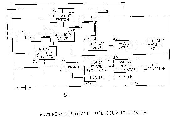
Figure 1 is a schematic representation of a propane
fu31 delivery system formed in accordance with the present
invention.
~tail~d ~scxi~ti~n_of the_erefQ~d E~o~i~Q~
The detailed description set forth below in connection
with the appended drawings is intended as a description of
the presently preferred embodiment o.E the invention, and is
not intended to represent the only form in which the
present inventio~ may be constructed or utili7ed. Th~
description sets forth the functions and sequence of steps
of constructing and operating the invention in connection
with the illustrated embodiments. It is understood,
howevar, that the same or equivalent functions and
sequence~ may be accomplished by different embodiments that
are also intended to be encompassed within the 6pirit and
scope of the invention.
Figure 1 is a block diagram illustrating the operation
of a propane fuel delivery system 11 formed in accordance
with the present invention. The syste~ includes a tank 13,
which i5 typically a liquid phase propane canister. The
tank 13 i5 connected to liquid phase regulator 17 via a
~irst fluid path through 601enoid valves 19 and 29. The
tank 13 is alternately connected to regulator 17 through a
second fluid path through pump 15 and sol~noid valve 29.
The pump 15 is activated by pressure switch 21.
Assuming the ambient temperature i8 suficiently high
the vapor pres6ure within tank 13 is ~ufficient to propel
propane through solenoid valve6 19 and 29 and to the liquid
~ ~3 ~ g ~
,,,, . ;,:
~i phase regulator 17, and thereafter to the vapor phase : i
i , "
;', regulator 31, which in turn regulates the gas pressure ~i
~ delivered to an external carburetor (not shown). The ~'
,~ ~ solenoid valve 29 is regulated by a vacuum switch 25 which '~
``. 5 is connected to the vacuum port of an internal combustio~ `'
engine (not shown). As long as the engine remains in
operation the vacuum switch 25 enables the solenoid 29 to
communicate propane from the regula~or 17 to the
carburetor. When the engine stops the vacuum switch 25
operates to disable the solenoid 29, preventing any further
flow of propane to the regulator 17.
Conventionally, when the ambient temperature falls
balow a certain level propane from tank 13 will elther not
reliably be communicated to regulator 17, or will be
communicated at a pre~fiure level too low to provide proper
output to vapor-phase regulator 31. The present invention
provides a means for responding to such a situation and for
~acilitating ~he operation of tha fuel delivery system
under such cold weather condition~. Pressure switch 21
operates to sense the pressure within tank 13 and to detect
pres6ure conditions which would pr~clude the reliable
delivery of propane to the regulator 31 via the jolenoid
valves 19 and 29. When such conditions are sen~ed tha
prassure switch 21 enables the operation of pump 15 80 as
to draw propane from the tank 13 through the pump 15, which
in turn communicates the propane to the regulator 17 under
sufficient pressure to insure proper output to vapor-phase
regulator 31. The operation of pressure switch 21 and
relay 23 closes solenoid valve 19 to prevsnt any back flow
through the solenoid valve 19 while the pump 15 is
operating. The pres~ure switch 21 is therefore operativa
to generate an enable signal which is communicated to pump
15 when the pre~sure within tank 13 fall6 below a variable,
predetermined thresholh. The same e~able ~ignal is also
333~ ~
-6-
communicated to relay 23 which operates to disable the
fluid flow through ~olenoid valve 19. Pump lS i8 tharefore
operative to pressurize the fluid flow to regulator 17 at
the right pressure to insure proper propane flow to the
carburetor, even when tank pressure is zero. Where the
ambient temperature reduces tank pre6sure below the minimum
operating point, it may be advisable to preheat the
regulators 17 and 31, by heaters 33, 35 for a predetermined
time before the pump lS is engaged and to continue to heat
1~ the regulators as long as the liquid propane temperature i~
below a predetermined threshold. Thermostat 27 ope.rates
to sense the temperature of the regulator 1? and enables
haatars 33 and 35 when the temperature of the regulator 17
falls below a predetermined threshold. In ac~ordance with
those procedures propane i6 provided to ths connected
internal combustion engine at the proper density and the
engine will run properly.
The opsration of pump 15 i3 therefore effective to
supplement the vapor pressure withi~ the tank 15 in order
to provide sufficient pressure on the fluid entering the
liquid phase regulator 17 to cause the output of regulator
17 to be in a vapor state. Ab~ent the exi~tence of pu~p 15
ths fluid vapor pressure within tank 13 may be too small to
provide a pressure differential across liquid phase
regulator 17 and, therefore, the propane may not be
transferred to a vapor phase.
The presfiure switch 21 is set at a threshold level of
tank pressure corresponding to the requirements of th~
liquid phase regulator 17. ~he pump 15 is activated when
the requirad pressure level at the input to liquid pha~e
regulator 17 falls below the pressure level necessary to
insure proper operation of the regulator 17. As will be
apparent to one of ordinary s~111 in the art the particular
threshold at which pres~ure switch 21 i8 set may be varied
in accordance with ~he particular implemen~ation and the
operattng characteristics of the equipment being used.
The present invention 18 effective to maintaln the
deltvery of vapor phase propane to an external carburetor,
independent of propane tank temperatures. The system
automatically supplements ~he vapor pressure within tank 13
when the pre~sure is insufficient to facilitate vapor phase
transition in the regulator 17. Thus, the present
invention directly supplements the pressure conditions
within the fuel delivery system, rather than affecting a
pres3ura change as a con3e~uence of heating the tank or
other portions of the system in a manner that may be more
cumbersome, less reliable, and more prone to accident and
in~ury.
In the presently preferred embodiment pump 15 is
implemented as a stainless steel cryogenic pump having a
magnetic drive, such as Model No. B9006M-B6729 manufactured
by Tuthill Pump Company, and pressure switch 21 i~
implemented as a Series V switch produced by Hobbs
Corporation. Additionally, the liquid phase regulator 17
may be implemented as a Model llA18 regulator produced by
J & S Carburetor Company. The vapor phase regulator 31 may
be implemented as a Model 50 regulator produced by Beam
Equipment. The heaters 33, 35 may be implemented as power
~S resistors attached to the regulators 17, 31 respectively.
In the presently preferred embodiment a series of 7 1/2 ohm
resistors are secured to the regulator~ in parallel, with
a total dissipation of approximately 90 watts for each
heater. The resistors may be similar to the model MP820
resistors marketed by Caddock Resistor Corporation. The
thermostat 27 may be implemented as a Model 3100 thermostat
switch produced by Elmwood Sensors Vacuum switch 25 may
be implemented as a Model 1501L switch produced by Beam
Eguipment. Solenoid valves 19, 29 may be implemented as
2~3~3~
--8--
Model FL218 valves, also produced by Beam Equipment. The
solenoid valvQs are preferably selected to remain operative
at temperatures of less than -30C.
As will be apparent to one of ordinary 6kill in the
art the precise components which form the present invention
may be varied in accordance with a particular application
in which the invention finds usage. Moreover, it is
anticipated that the invention may have application beyond
propane fuel delivery systems and, in its broader aspects,
extend~ to variou6 types of gaseous fuel delivery 6y6tems.
Tha~e and other modifications, enhancements and addition~
will be apparent to one of ordinary skill in the art and
are not intended to serve as limitations on the broader
aspects of the present lnvention.