Language selection

Search

Patent 2038617 Summary

Third-party information liability

Some of the information on this Web page has been provided by external sources. The Government of Canada is not responsible for the accuracy, reliability or currency of the information supplied by external sources. Users wishing to rely upon this information should consult directly with the source of the information. Content provided by external sources is not subject to official languages, privacy and accessibility requirements.

Claims and Abstract availability

Any discrepancies in the text and image of the Claims and Abstract are due to differing posting times. Text of the Claims and Abstract are posted:

  • At the time the application is open to public inspection;
  • At the time of issue of the patent (grant).
(12) Patent Application: (11) CA 2038617
(54) English Title: REMOVABLE FILTER FLUID FLOW SHUTOFF APPARATUS
(54) French Title: BLOC D'ALIMENTATION EN FLUIDE, A FILTRE AMOVIBLE
Status: Deemed Abandoned and Beyond the Period of Reinstatement - Pending Response to Notice of Disregarded Communication
Bibliographic Data
(51) International Patent Classification (IPC):
  • B25D 17/00 (2006.01)
(72) Inventors :
  • LYON, LELAND H. (United States of America)
  • EGGELING, RICHARD L. (United States of America)
  • LYON, LELAND H. (United States of America)
  • EGGELING, RICHARD L.
(73) Owners :
  • INGERSOLL-RAND COMPANY
(71) Applicants :
  • INGERSOLL-RAND COMPANY (United States of America)
(74) Agent: SWABEY OGILVY RENAULT
(74) Associate agent:
(45) Issued:
(22) Filed Date: 1991-03-19
(41) Open to Public Inspection: 1992-09-20
Examination requested: 1991-07-18
Availability of licence: N/A
Dedicated to the Public: N/A
(25) Language of filing: English

Patent Cooperation Treaty (PCT): No

(30) Application Priority Data: None

Abstracts

English Abstract


ABSTRACT OF THE DISCLOSURE
A filter apparatus for a percussion device powered by
fluid pressure includes a percussion device housing having a
fluid inlet and a fluid outlet. A valve is displaced
between an open and a closed position. A filter recess is
formed within the housing. A filter is inserted within the
filter recess for moving the valve from the closed to the
open position, thereby permitting fluid pressure to be
supplied from the inlet to the outlet.
-8-


Claims

Note: Claims are shown in the official language in which they were submitted.

THE EMBODIMENTS OF THE INVENTION IN WHICH AN EXCLUSIVE
PROPERTY OR PRIVILEGE IS CLAIMED ARE DEFINED AS FOLLOWS:
Having described the invention, what is claimed is:
1. A filter apparatus for a percussion device powered by
fluid pressure comprising:
a percussion device housing;
a fluid inlet and a fluid outlet within the percussion
device housing;
valve means movable between an open and a closed
position;
a filter recess formed within the housing; and
filter means inserted within the filter recess for
moving the valve from the closed to the open position
thereby permitting fluid pressure to be supplied from the
inlet to the outlet.
2. The apparatus as defined in claim 1, further
comprising:
a passage interconnecting the inlet with the outlet.
3. The apparatus as defined in claim 1, further
comprising:
spring means for biasing the valve means to a closed
position.
4. The apparatus as defined in claim 1, wherein the valve
means further comprises a shoulder means which the filter
means acts against for biasing the valve from a closed to an
open position.
-6-

5. The apparatus as defined in claim 4, wherein the
shoulder means forms a seal with the valve means when the
shoulder means and a valve means are in contact.
-7-

Description

Note: Descriptions are shown in the official language in which they were submitted.


~ 0 3:8 6 ~ 7 ~
Docket ~O 0902-IR-MC
REMOVABLE FILTER FLUID FLOW SHUTOFF APPARATUS
BACKGROUND OF THE INVENTION
This invention relates generally to a filter for a
percus~ion device, and mor~ specifically a filter to be
~ used in a rock drill and contalned within the housing of
the rock drill. The rock drill is to be powered by an
impure fluid such as water.
Previously, rock drills have been constructed with
the filter element connected with the rock drill by a hose
element. This configuratlon is awkward considering the
weight o~ the filter and the small work space in which the
rock drill is typically used.
This conflguration also per~itted operation of the
percussion device with the ~llter disconnected from the
percussion device. Since the fluid used in these
applications is o~ten conta~inated, this reduced the
lifetime o~ th~ percussion device considerably.
- , . . . ` : .

2038617
Docket ~ 0902-IR-MC
The foregoing illustrate~ limitations known to exist
in present rock drills. Thus, it is apparent that it would
be advantageous to provide an alternative directed to
overco~ing one or more of the l~tations set forth above.
Accordingly, a suitable alternatlve i8 provided including
features ~ore fully disclosed hereinafter.
SUMMARY OF ~HE INVENTION
In one aspect of the present invention, this is
accomplished by providing a filter apparatus for a
percus6ion device powered by fluid pressure comprising a
percuss~on dQvice housing. The ~ilter apparatus has a fluid
inlet and a fluid outlet.
A valve is displaceable between an open and a closed
position. A filter recess is formed within'the housing. A
filter is inserted within tAe ~ilter recess for moving the
valve from the closed to the open position, thereby
per~ittlng fluid pressure to be ~upplied from the inlet to
the outlet.
~: '
The foregoing and other aspects will become apparent
from the following detailed description of the invention
when considered in conjunction with the accompanying drawing
figure~.

20~8617
Docket No.: 0902-IR-MC
BRIEF D~SCRIPTION OF THE D~AWING FIGURES
Fig. 1 is a side view of a per~ussion device
illustxating one embodiment of the location of the shutoff
valve o~ the in~tant invention;
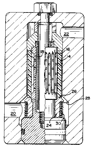
Fig. 2 is a split cross sectional view on the left
side of the figure, and an elevation view on the right side
of the figure, illustrating an embodiment of the removable
filter flow shutoff apparatus of the in~tant invention, with
the ~ilter in the inssrted position; and
Fig. 3 is a cros~ sectional view of the valve portion
of Fi~. 2 with the valve in the clo~ed position.
DE~AILED DESC~IPTION
~ .'
A percussion device shown gener~lly at 10, such as a
jackhammer, is formed with a housing 12. An internal filter
recess 14 is formed within the hou~ing 12. A filter-i6,
which is mounted on a filter apparatus 18, i8 removably
di~pos2d within tha rece~s 14.
~ : :
The filt~r 16 is us~d to filter a fluid, such a~ water . .
or air, used in the operation of the percussion device.
During the normal operatlon of the percussion device 10,
fluid pa~sing fro~
.
--3--
:. : : , , . . , .; .. . . . .

2038617
Docket No.: 0902-IR-MC
a fluid inlet 20 to a fluid outlet Z2 must pass through
filter 16. The fluid passing through the filter outlet 22
will be used to operate the percussion device.
A valve ~ean~ 24 can be displaced between an open
position (as shown in Fig. 21, and a clossd position (a~
shown in Fig 3). When the val~ i~ in a closed po~ition, a
shoulder 26 of the valve mean 24 acts against a ~alve seat
means 28, and acts as a seal to prevent the flow of ~luid :
from the fluid inlet 20 to the ~luid outlet 22. Whenever
the valve 24 is open, the fluid flows freely between the
inlet and the outlet. :
Insertion of the filter apparatus 18 into the filter
recess 14 with the filter 16 on the ~ilter apparatus w~
cause t~e filter 16 to act against the shoulder 26. This
will displace valve mean~ 24 from the closed to the open
position, and per~it t~e proper functioning of the
percussion device 10.
However, if the filter apparatus 18 is inserted into
the filter recess 14 with the f~lter 16 removed from the
filter apparatus 18, the valve means 24 will remain seated
against the valve seat means 28 under the force of a spring ~`
30. Fluid passing from th~ inlet 20 to the outlet 22 will
therefore be blocked, and the percussion device will be
inoperative.
- : :,

2038617
Docket ~o.: oso2-IR-Mc
This configuration en~ures that the percussion device
10 will be able to be operated only on fluid which has
pa~sed through filter 16, and enca~e~ the bulky filter
element within the percussion davice housing 12.

Representative Drawing
A single figure which represents the drawing illustrating the invention.
Administrative Status

2024-08-01:As part of the Next Generation Patents (NGP) transition, the Canadian Patents Database (CPD) now contains a more detailed Event History, which replicates the Event Log of our new back-office solution.

Please note that "Inactive:" events refers to events no longer in use in our new back-office solution.

For a clearer understanding of the status of the application/patent presented on this page, the site Disclaimer , as well as the definitions for Patent , Event History , Maintenance Fee  and Payment History  should be consulted.

Event History

Description Date
Time Limit for Reversal Expired 1993-09-21
Application Not Reinstated by Deadline 1993-09-21
Deemed Abandoned - Failure to Respond to Maintenance Fee Notice 1993-03-19
Inactive: Adhoc Request Documented 1993-03-19
Application Published (Open to Public Inspection) 1992-09-20
Request for Examination Requirements Determined Compliant 1991-07-18
All Requirements for Examination Determined Compliant 1991-07-18

Abandonment History

Abandonment Date Reason Reinstatement Date
1993-03-19
Owners on Record

Note: Records showing the ownership history in alphabetical order.

Current Owners on Record
INGERSOLL-RAND COMPANY
Past Owners on Record
LELAND H. LYON
RICHARD L. EGGELING
Past Owners that do not appear in the "Owners on Record" listing will appear in other documentation within the application.
Documents

To view selected files, please enter reCAPTCHA code :


To view images, click a link in the Document Description column. To download the documents, select one or more checkboxes in the first column and then click the "Download Selected in PDF format (Zip Archive)" or the "Download Selected as Single PDF" button.

List of published and non-published patent-specific documents on the CPD .

If you have any difficulty accessing content, you can call the Client Service Centre at 1-866-997-1936 or send them an e-mail at CIPO Client Service Centre.


Document
Description 
Date
(yyyy-mm-dd) 
Number of pages   Size of Image (KB) 
Cover Page 1992-09-20 1 27
Claims 1992-09-20 2 50
Drawings 1992-09-20 1 42
Abstract 1992-09-20 1 26
Descriptions 1992-09-20 5 163
Representative drawing 1999-04-06 1 30