Language selection

Search

Patent 2038689 Summary

Third-party information liability

Some of the information on this Web page has been provided by external sources. The Government of Canada is not responsible for the accuracy, reliability or currency of the information supplied by external sources. Users wishing to rely upon this information should consult directly with the source of the information. Content provided by external sources is not subject to official languages, privacy and accessibility requirements.

Claims and Abstract availability

Any discrepancies in the text and image of the Claims and Abstract are due to differing posting times. Text of the Claims and Abstract are posted:

  • At the time the application is open to public inspection;
  • At the time of issue of the patent (grant).
(12) Patent: (11) CA 2038689
(54) English Title: HAND SCANNER FOR READING BAR CODES
(54) French Title: LECTEUR DE CODES A BARRES TENANT DANS LA MAIN
Status: Deemed expired
Bibliographic Data
(52) Canadian Patent Classification (CPC):
  • 352/53.74
(51) International Patent Classification (IPC):
  • G06K 9/22 (2006.01)
  • G06K 7/10 (2006.01)
(72) Inventors :
  • BENGTSSON, KJELL (Sweden)
(73) Owners :
  • METO INTERNATIONAL GMBH (Germany)
(71) Applicants :
(74) Agent: RIDOUT & MAYBEE LLP
(74) Associate agent:
(45) Issued: 2001-08-21
(22) Filed Date: 1991-03-20
(41) Open to Public Inspection: 1991-09-21
Examination requested: 1998-03-20
Availability of licence: N/A
(25) Language of filing: English

Patent Cooperation Treaty (PCT): No

(30) Application Priority Data:
Application No. Country/Territory Date
9001003-4 Sweden 1990-03-20

Abstracts

English Abstract


A hand scanner intended for optically reading a bar code on an item
of goods and therewith produce an electric signal which corresponds
to the read bar code. The invention is characterized in that the hand
scanner (1) is provided with one or more permanent magnets (3, 4) in
the vicinity of its optical bar-code reading device


Claims

Note: Claims are shown in the official language in which they were submitted.


5

THE EMBODIMENTS OF THE INVENTION IN WHICH AN EXCLUSIVE
PROPERTY OR PRIVILEGE IS CLAIMED ARE DEFINED AS FOLLOWS:

1. A hand scanner intended for optically reading a bar code on an
item of goods and therewith produce an electric signal corresponding
to the bar code that is read-off, characterized in
that said hand scanner (1) is provided with one or more permanent
magnets (3, 4) in the vicinity of its optical bar-code reading device.

2. A hand scanner according to Claim 1 in that case when said scanner
(1) is of the kind having an outwardly projecting rectangular opening
(2) and in which said optical device is located inwardly of said
opening, characterized in that said magnet or magnets
(3, 4) is/are placed in said opening (2).

3. A hand scanner according to Claim 1 or 2, characteri-
zed by one or more pairs of permanent magnets, where the magnets
(3, 4) of each pair of magnets are positioned adjacent one another in
a plane which is substantially parallel to the plane in which the bar
code is located when being read; and further characterized in that
the south pole of a first magnet (4) of said pair is located on a
magnet surface which faces away from the scanner and the north pole
of said first magnet is located on a surface which faces in towards
the scanner; and in that the respective south and north poles of a
second magnet (3) of said pair face in opposite directions.

Description

Note: Descriptions are shown in the official language in which they were submitted.


1
A hand scanner for readirxr bar codes
The present invention relates to a hand-held scanner for reading
bar codes applied on items of goods.
It has became more usual to provide items of goods offerc~ for sale
in self-service stores with a bar code which is read-off at the cash
desk of the store, thereby to record autcm~~::ically the price of said
item, among other things. One alternative in this regard is the use
of a so-called hand scanner, i.e. a scanner which is held by the
cashier and passed over the bar code on the goods item concerned,
said scanner reading the bar code optically and delivpxirx~ to a
carnputer or microprocessor an electric signal which corresponds to
the information contained in the bar code.
It has also beco~ progressively more usual in recent times to provide
price-tagged goods with a magnetic alax~n strip in conjL~nction with the
price tags, said stxips being intended to coast with transmitter
coils and receivex coils positioned in 'the vicinity of the cash desk
~or an emit, so that if a customer fails to present an item of goods
for payment, an alarm signal is triggered when the goods item is pass
between the coils.
In order to prevent the triggering of an alarm xsy goods which have
been paid for, the,alarm strip on the price tag is deactivated by
exposing the strip to a powerful. permanent magnetic field. At present,
this is effected by holding the price 'tag close to a fixedly mounted
pea:manent magnet. this method necessitates the cashier first to pass
the goods past the scanner with the bar code on the goods facing
~0 towards the scanner and. then to move the price tag on the goods
against the permanent magnet. Thus, the cashier is required to perform
two different procedural steps, namely one step involving recording
the item of goods by reading the bar c~le and and another step
involving deactivation of the alarm strip.
The present invention relates to a device which enables these two
procedures to 3~ carried out in only one single prace~iu~'al step. The
present invention provides a considerable improvement, when seen


2
against the background of the very large number of goods items handled
by a cashier at the cash desk.
Thus, the present invention relates to a hand scanner which is intended
to read optically a Saar code located on an item of goods and therewith
produce an electric signal which corresponds to the bar code read by
the scanner, and is charac~ex°iz~1 in that said hand scanner is
provided
with one or more permanent magnets in the proximity of its optical
reading means.
The invention will now be described in more detail with reference to
an exemplifying embodiment thereof illustrated in the accomxaanying
drawings, in which
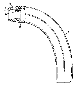
- Figure 1 is a side view of an inventive hand scanners with the
front part shown in cross--section;
-- Figure 2 is a front view of an inventive hand scanner, and
- Figure 3 illustrates magnets in perspective. and in larger scale.
Figures 1 and 2 illustrate a hand scanner 1 intended for optically
reading a bar code on an item of goods and ther'ewi'th produce an
electric signal which corresponds to the bar code read by the scanner.
Such hand scanners are kn~an and are general in commerce, primarily
in general stores. Orae type of hand scanner, namely the hand scarmer
illustrated in the Figures, is configured with an outwardly projecting,
rectangular openins~ 2 and includes a lawn optical bar-code reading
deuice (not shown) which is located inwardly of said off.
The opening 2 is at least equally as large as the dimensions of the bar
code to be read. When reading-off a bar code, the scanner opening is
positioned over the bar code and the code is read without moving 'the
scanner.
Zn accordance with the irivention, the aforesaid hand scanner is
provided with one or more permanent magnets 3, 4 in the vicinity of
the optical bar--code readizzg device.
According to one preferred embadament, said magnet or magnets 3; 4
are disposed in 'the opening 2. A conventional type of hard scanner is
provided with a rubber cuff or sleeve 5 which is fitted anto the


3
plastic casing 6 of the scanner. In the case of this ty~ of scanner
it is suitable to attach the magnets between the rubber cuff and the
plastic casing. Magnets which are positioned in the manner shown in
Figiaz~e 1 will not interfere with the cashier ° s handling of the
scanner'.
When the scanner is moved to a position above/over 'the bar code, the
alarm strip on the price tag will be deactivated by means of the
permanent magnet or magnets 3, 4, in that the magnetic field from the
magnet or magnets will magnetize magnetic sections on the alarm
strip, so that the alarm strip will no longer transmit intex~adulation
products of sufficient strerx~th to be detected when the alarm strip
is exposed to a magnetic alternating field having at least t-wa
frequencies.
Depending on its, or their, position the magnet or magnets will
produce a permanent magnetic field having a given field pattern which
is more or less advantageous for the purpose in question.
According to a preferred embodiment, one or more pairs of permanent
2p magnets are provided. In the illustrated embodiment, one pair of
permanent magnets 3, 4 is provided. In this case, the magnets of each
pair of magnets are placed adjacent one another in a plans which is
substantially parallel to the plane in which the bar code is located
when read-off . 7~his plane is perpendi.cul-ar to ''the plane of the paper
in Figure 1. Furthermore, the south pole of a first magnet 4 is
located on a magnet surface which faces away from the scanner, while
the north pole is located on a surface which faces in towards the
scanxier. The respective south and north poles of the other magnet 3
of said pair face :un opposite directions thereto, see Figures 2 and 3
in which the south poles and north poles are referenced S and N res-
pectively. This positioning produces a powerful magnetic field in
front of the scanner openi~.
As will be understood, several pairs of magnets can be placed adjacent
one another in the manner illustrated in Figure 3.
In order for a hard scanner of the present kind to provide the effect
inter~led, it is rece scary t3~at the price tag or label provided with


4
an alarm strip is positioned close to or in the immediate vicinity of
the bar c~le on said item of goods. 'this presents no problem, however,
since the person who price-marks 'the goods can be instructed to place
the price tags in the immediate vicinity of the bar cede. If a price
tag is placed 'too far away frrnn the har cods', it suffices for the
cashier to move the hand scanner to the price tag so as to deactivate
the alarm strip.
The invention has been described above with reference to one type of
hand scanner. The invention can also be applied, however, with so-
called pen-readers of the kind which are drawn alor~ the bar code. In
this case, a pair of magnets can be plar.~l on opposite sides of the
tip of the pen reader, for instance.
It is evident that 'the present invention will overcome the drawbacks
mentioned in the introduction, since the price tag is cleactiva~ted
when reading the bar code. This obviates one of the steps earlier
requir~l of the cashier, while eliminating, at the same time, 'the
risk of an alarm being triggered by an item of goods for which payment
has been made, due to the casY~.ier forgetting to deactivate the price
tag. An alarm which is triggered by mistake in this way is ex~xienced
as being highly troublesome by the customer's involved.
'Tfie invention has been described in the aforegoing with reference to
various embodiments. It will be understood, however, that modifications
can be made by the.skilled person, so as to adapt these embodiments
to different types of hand scanners, pen readers or the like.
The invention is therefore not restricted to the aforedesoribed
embodiments, since modifications and variations can be made within
the s~pe of the following claims.

Representative Drawing
A single figure which represents the drawing illustrating the invention.
Administrative Status

For a clearer understanding of the status of the application/patent presented on this page, the site Disclaimer , as well as the definitions for Patent , Administrative Status , Maintenance Fee  and Payment History  should be consulted.

Administrative Status

Title Date
Forecasted Issue Date 2001-08-21
(22) Filed 1991-03-20
(41) Open to Public Inspection 1991-09-21
Examination Requested 1998-03-20
(45) Issued 2001-08-21
Deemed Expired 2009-03-20

Abandonment History

There is no abandonment history.

Payment History

Fee Type Anniversary Year Due Date Amount Paid Paid Date
Application Fee $0.00 1991-03-20
Registration of a document - section 124 $0.00 1993-03-09
Maintenance Fee - Application - New Act 2 1993-03-22 $100.00 1993-03-12
Maintenance Fee - Application - New Act 3 1994-03-21 $100.00 1994-02-18
Registration of a document - section 124 $0.00 1994-03-18
Maintenance Fee - Application - New Act 4 1995-03-20 $100.00 1995-02-28
Maintenance Fee - Application - New Act 5 1996-03-20 $150.00 1996-02-20
Maintenance Fee - Application - New Act 6 1997-03-20 $150.00 1997-02-24
Maintenance Fee - Application - New Act 7 1998-03-20 $150.00 1998-02-23
Request for Examination $400.00 1998-03-20
Maintenance Fee - Application - New Act 8 1999-03-22 $150.00 1999-02-23
Maintenance Fee - Application - New Act 9 2000-03-20 $150.00 2000-02-16
Registration of a document - section 124 $50.00 2001-02-23
Maintenance Fee - Application - New Act 10 2001-03-20 $200.00 2001-02-27
Final Fee $300.00 2001-05-01
Maintenance Fee - Patent - New Act 11 2002-03-20 $200.00 2002-02-14
Maintenance Fee - Patent - New Act 12 2003-03-20 $200.00 2003-02-04
Maintenance Fee - Patent - New Act 13 2004-03-22 $200.00 2003-12-16
Maintenance Fee - Patent - New Act 14 2005-03-21 $250.00 2005-03-04
Maintenance Fee - Patent - New Act 15 2006-03-20 $450.00 2006-03-01
Maintenance Fee - Patent - New Act 16 2007-03-20 $450.00 2007-03-01
Owners on Record

Note: Records showing the ownership history in alphabetical order.

Current Owners on Record
METO INTERNATIONAL GMBH
Past Owners on Record
BENGTSSON, KJELL
ESSELTE METO EAS INT. AB
ESSELTE METO INTERNATIONAL GMBH
Past Owners that do not appear in the "Owners on Record" listing will appear in other documentation within the application.
Documents

To view selected files, please enter reCAPTCHA code :


To view images, click a link in the Document Description column. To download the documents, select one or more checkboxes in the first column and then click the "Download Selected in PDF format (Zip Archive)" or the "Download Selected as Single PDF" button.

List of published and non-published patent-specific documents on the CPD .

If you have any difficulty accessing content, you can call the Client Service Centre at 1-866-997-1936 or send them an e-mail at CIPO Client Service Centre.


Document
Description 
Date
(yyyy-mm-dd) 
Number of pages   Size of Image (KB) 
Abstract 1994-03-30 1 12
Representative Drawing 1999-07-20 1 6
Claims 1994-03-30 1 45
Drawings 1994-03-30 1 28
Description 1994-03-30 4 234
Cover Page 1994-03-30 1 18
Claims 2000-09-19 1 41
Abstract 2000-09-19 1 13
Cover Page 2001-08-06 1 29
Representative Drawing 2001-08-06 1 6
Fees 2000-02-16 1 30
Fees 2001-02-27 1 34
Fees 2002-02-14 1 31
Correspondence 2003-02-21 1 14
Fees 2003-02-14 1 36
Fees 1999-02-23 1 33
Assignment 1991-03-20 13 452
Prosecution-Amendment 1998-03-20 2 54
Prosecution-Amendment 2000-07-24 1 24
Prosecution-Amendment 2000-09-19 4 106
Assignment 2001-02-23 1 56
Correspondence 2001-05-31 1 14
Correspondence 2001-05-01 1 47
Assignment 2001-06-06 2 94
Correspondence 2001-06-08 1 12
Prosecution-Amendment 1998-11-05 2 69
Fees 1998-02-23 1 30
Fees 1997-02-24 1 27
Fees 1995-02-28 1 67
Fees 1996-02-20 1 24
Fees 1994-02-18 1 49
Fees 1993-03-12 1 27