Note: Descriptions are shown in the official language in which they were submitted.
~ 3~7 ~ ~
OFFSET PRINTING PRESS WITII INIERI~IEDIATE KOLLER FOR THE
CONNECTION OF INKING UNIT AND DAMPING U~IT
Specification
The invention relates to a printing press with an inking
unit and with a damping unit, with inking unit and
damping unit comprising inking roller and damping-
solution applicator roller - said inking roller and
damping-solution applicator roller cooperating with a
printing forme - as well as being connectable through
the intermediary of at leas~ one intermediate roller.
In certain operating situations of an offset printing
press, it may be advantageous for inking unit and
damping unit to be connected to one another through the
intermediary of an intermediate roller. If, for
example, it is desired that there should be pre-damping,
then inking roller and damping-solution applicator
roller assume disengaged positions with respect to the
plate cylinder of the offset printing press and are
connected to one another through the intermediary of the
intermediate roller. The damping solution, delivered
from the damping-solution box by a fountain roller of
the damping unit, is supplied via a metering roller and,
if applicable, further rollers to the damping-solution
applicator roller, from where it is supplied via the
intermediate roller to the first (as viewed in the
direction of rotation of the plate cylinder) inking
roller and thus to the inking unit. Also during a
production run, it may be advantageous for the inking
roller and damping-solution applicator roller, in
contact with the plate c~linder, to be connected to one
another through the intermediary of the intermediate
roller. Printing presses are known in which, in the
operating positions "washing position" and "printing
stop", the intermediate roller is in contact with the
inking roller and with the damping-solution applicator
20~7~
roller. In special situations, for example in the case
of emulsification problems or the use of formes with
extremely low ink acceptance with the simultaneous
requirement for high ink-film thickness or even the use
of metal-based inks, it may be of ad~antage to interrupt
the connection with the inking unit, i.e. the
intermediate roller is then in contact only with the
damping-solution applicator roller. This position is
designated also as the so-called "small separation".
Known also is a so-called "large separation", in which
the intermediate roller is moved in such a manner that
it is in contact only with the first inking roller.
Here, for example, by lateral traversing, it is able to
counteract the phenomenon of stencilling.
Known from the German registered-design specification
1 932 642 is an offset printing press provided with at
least one intermediate roller. The intermediate roller
is held on a swivel frame, which is manually swivelable
by means of a lever arrangement, as a result of which
the intermediate roller can be brought into a disengaged
or engaged position with respect to the inking roller
and the damping-solution applicatGr roller.
The German patent specification 23 43 935 describes a
damping unit for an offset printing press in which, in
the case of brief interruptions in printing with the
inking roller disengaged as well as with the
intermediate roller lifted off the latter, the supply of
damping solution to the inking unit is prevented and is
reduced in the damping unit. For this purpose, the
intermediate roller is in contact merely with the
damping-solution applicator roller but not with the
inking roller. In the operating position "printing
start", the intermediate roller connects inking unit and
damping unit.
2~3~77~
Finally, US-PS 3 911 815 discloses an offset printing
press with an intermediate roller, said intermediate
roller ~eing held on a swivel frame, on which is
situated an applicator roller, said applicator roller
carrying both damping solution and also ink. If the
swivel frame assumes its engaged position, the
applicator roller cooperates with the plate cylinder and
the intermediate roller cooperates with a damping-
solution-carrying roller of the damping unit. With the
swivel frame, which is movable through the intermediary
oi a piston/cylinder unit, in the disengaged position,
the applicator roller remains in contact with the
intermediate roller; there is, however, a disengaged
position between the applicator roller and the plate
cylinder as well as between the intermediate roller and
the roller of the damping unit.
The object of the invention is to create an offset
printing press that allows particularly versatile,
economic operational management of the printing press in
order to achieve optimum printing results. It is, in
particular, also to be possible to shorten set-up times.
The object of the invention is achieved in that the
intermediate roller i~ held position-variably in such a
manner that its position with respect to the inking
roller and/or damping-solution applicator roller is
freely selectably adjustable on a situation-related
basis.
This makes it possible, in any operating position of the
offset printing press, to bring the intermediate roller
into engagement only with the inking roller or Gnly with
the damping-solution applicator roller or to establish a
connection between inking roller and damping-solution
2~33~7 ~
applicator roller. This is completely irrespective of
the positions ~engaged or disengaged position with
respect to the plate cylinder) of the inking and/or
damping-solution applicator rollers. Finally, the
freely selectable movability of the intermediate roller
permits a position in which there is a connection
neither with the inking roller nor with the damping-
solution applicator roller. In contrast to the prior
art, therefore, there is no positive mechanical control
of the intermediate roller allowing merely fixed
positions of the intermediate roller and, if applicable,
of further rollers, but completely free operational
management is made possible with regard to the
intermediate roller, with the result that, on a
situation-related basis, i.e. depending on the
respective operating state of the offset printing press
and on other parameters, it is possible for the
intermediate roller to be used in accordance with the
desired requirements. In this connection, it is even
conceivable for the position of the intermediate roller
to be changed while the operating state of the offset
printing press otherwise remains the same.
According to a further development of the invention,
there are provided at least two actuators, said
actuators effecting the positioning of bearing points
of the intermediate roller and the directions of action
of said actuators enclosing an angle. This makes it
possible to move the bearing points of the intermediate
roller in such a manner that it is able to assume the
desired position (connected position between inking
roller and damping-solution applicator roller,
connection with the inking roller, connection with the
damping-solution applicator roller, no connection with
inking roller or damping-solution applicator roller).
Since, preferably, the operating element of each
~3877 7
actuator is movable into two positions and the
directions of ac~ion of both actuators enclose an angle,
the four aforemen~ioned positions of the intermediate
roller can be achieved by suitable, free activation.
Preferably, at least one actuator is in the ~orm of a
piston~cylinder unit. Preferably, both actuators are of
this design. Alternativel~, however, it is also
possible for only one piston/cylinder unit to be
provided and for the other ac~uator to be in the form of
a spring. Preferably, the spring is a compression
spring, particularly a helical compression spring. This
leads to an economy version with limited positional
versatility of the intermediate roller.
Since, as already mentioned, the inking roller and the
damping-solution applicator roller are preferably
likewise freely movable in their positions in relation
to the printing forme (plate cylinder provided with
printing plate) and since, moreover, there is the free
selectability according to the invention of the
intermediate roller, this permits a multiplicity of
constellations of said rollers, allowing optimum
operational management depending on the respective
situation.
It is possible in this context for the positioning of
the intermediate roller and/or of the inking roller
and/or of the damping-solution applicator roller to be
accomplished manually or by a program of a printing-
press control. The positioning of the intermediate
roller and/or of the inking roller and/or of the
damping-solution applicator roller may be accomplished,
in particular, also b~ remote control (for example from
the machine-control console). The printer thus has the
opportunity suitably to position the intermediate
2038~77
roller depending on the current si~uation. The printing
press may be, for example, in "spinning mode", i.e. its
rollers are rotating, but nothing is being printed. The
following are conceivable as further "situations": the
printing press has just stopped printing; the printing
press has just started printing; the aforementioned
situations with or without inking on the corresponding
rollers; t~le printing press is running on; the printing
press is in a washing position, etc. The free
controllability of the intermediate roller also makes it
possible to assume specific positions at intervals or
iteratively. This may be accomplished both manually by
the printer and also under the control of a program. In
particular, it is possible to implement a link with a
program-controlled remote control for ink and register.
Program interconnections may be provided also for an
automatic apparatus for measuring the ink density as
well as for determining the ink demand and for automatic
presetting of the inking of the offset printing press.
In each of the described cases, it is possible not only
for the current situation to be analyzed and for the
intermediate roller to be suitably positioned, but also
for the computer to take account of previous and/or
future operating situations in order to position the
intermediate roller and, if applicable, inking and/or
damping-solution applicator rollers for optimum
operational management.
The invention relates further to a process for the
operation of an offset printing press provided with
inking unit and damping unit, with inking unit and
damping unit comprising inking roller and damping-
solution applicator roller - said inking roller and
damping-solution applicator roller cooperating with a
printing forme - as well as being connectable through
the intermediary of at least one intermediate roller,
- ~3~7~
and in which the intermediate roller is held position-
variably in such a manner that its position wi~h respect
to the inking roller and/or damping-solution applicator
roller is ~reely selectably movable on a situa~ion-
related basis. The situation-related position of the
intermediate roller is, as already mentioned, dependent
on the current and/or previous and/or fu~ure operating
states of the offset printing press.
The invention is illustrated with reference to a
spacimen embodiment in the drawings, in which:
Fig. 1 shows a diagram of rollers in an offset
printing press;
Fig. 2 shows the diagram of rollers from Fig. 1, but
in different positions; and
Fig. 3 shows an intermediate roller, said intermediate
roller being freely movable by means o~
actuators and being disposed between the
damping and inking units of the offset printing
press.
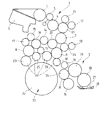
Fig. 1 shows a diagram of rollers in an offset printing
press (printing press not represented in any greater
detail). An inking unit 1 and a damping unit 2 are
provided. The inking unit 1 comprises an ink duct 3
with an ink-metering apparatus. An ink-duct roller 4
withdraws ink in metered manner from the ink duct 3
during operation. A vibrator 5 cooperates with the ink-
duct roller 4 as well as with a driven distributor 6.
Inking unit 1 and damping unit 2 additionally comprise
further driven distributors 7, 8, 9 and 10. In
addition, there are six rider and transfer rollers 11 to
16 and nine rubber-covered rollers 17 to 25. The
2~38~77
damping unit 2 comprises a damping-solution box 26
filled with damping solu~ion 27, with a fountain roller
28 being partially immersed in the damping solution 27.
The fountain roller 28 cooperates with a metering roller
29. Further provided are a rubber-covered roller 30 and
an intermediate roller 31.
Both ink and damping solution are supplied to a printing
forme 32 ~ia the described roller arrangement. The
printing iorme 32 is a printing plate (not shown), said
printing plate being clamped onto a plate cylinder 33.
The transfer of ink and damping solution from the inking
unit l and damping unit 2, respectively, to the printing
plate is effected by the rubber-covered rollers 18, 20,
23~ 25 and 30~ Consequently, the rubber-covered rollers
18~ 20~ 23 and 25 are called inking rollers 34 and the
rub~er-covered roller 30 assigned to the damping unit 2
is called a damping-solution applicator roller 35. The
inkins roller cooperating with the intermediate roller
31 forms - as viewed in the direction of rotation o~
the plate cylinder 33 - a first inking roller 34.
By means of a control device (not shown) it is possible
for the inking rollers 34 and the damping-solution
applicator roller 35 to be moved out o~ their
disengaged positions with respect to the plate cylinder
33 in such a manner that they are brought into
engagement with the plate cylinder 33 (Fig. 2)o The
positions of the inking and damping-solution applicator
rollers 34, 35 are dependent on the operating state of
the offset printing press.
The aforementioned intermediate roller 31 can, according
to the invention, assume different positions in that -
irrespective of the positions of the inking rollers 34
and/or of the damping-solution applicator roller 35 - it
203~77
g
either connects the first inking roller 34 to the
damping-solution applicator roller 35 or is in contact
only with ~he first inking roller 34 or cooperates only
with the damping-solution applicator roller 35 or,
finally, assumes a disengaged position both with respect
to the first in~ing roller 34 and also with respect to
the damping-solution applicator roller 35. Fig. 2
shows the position in which the intermediate roller 31
is in engagement with the inking roller 34 and with the
damping-solution applicator roller 35. Fig. 1 shows the
disengaged position with respect to both rollers. Owing
to the simple state of affairs, the other two positions
(engaged position with respect only to the first inking
roller 34; engaged position with respect only ~o the
damping-solution applicator roller 35) are not shown
separately in the Figures.
According to the invention, therefore, the position of
the intermediate roller 31 is situation-related; that
is, it is freely selectably adjustable or movable
depending on the current or desired operating state of
the offset printing press. The positioning of the
intermediate roller 31 can be accomplished either
manually or, alternatively, by means of a program of a
printing-press control. For manual control it is
advantageous if this is performed under remote control
from the machine-control console. This free
controllability of the intermediate roller 31 allows
the printer to intervene on a situation-related basis to
influence the distribution of ink and damping solution,
with it also being possible, as an alternative to a
"permanent position", for the printer to move the
intermediate roller 31 into a desired position for
specific lengths of time. An iterative mode of
operation is also possible. The same applies also to
the aforementioned program control, with it also being
2~3~777
possible here for the computer of the printing-press
con~rol additionally to make use o~ the previously
existing operating states as a decision-making criterion
for the position of the intermediate roller 31.
Furthermore, it is conceivable also to take account of
future operating states, already stored in the control
program of the printing press, when the decision is made
with regard to the instantaneous position of the
intermediate roller 31.
Fig. 3 shows, in the region of the intermediate roller
31, a part of the diagram of rollers of the offset
printing press. The intermediate roller 31, which is in
the form of a traversing roller, is held on a U-shaped
carrier 36. The bearing points of the intermediate
roller 31 are disposed on a web region 37 on the carrier
36, with a first arm 38 and a second arm 39 issuing from
the web region 37. In the position shown in Fig. 3, in
which the intermediate roller 31 is in contac~ wi~h the
first inking roller 34 and with the damping-solution
applicator roller 35, with inking roller 34 and damping-
solution applicator roller 35 assuming their engaged
positions with respect to the plate cylinder 33, the two
longitudinal axes of the arms 38 and 39 form an angle a
with respect to the horizontal 40. The angle a lies
preferably in the range between 20 and 40,
particularly at 30. The two arms 38 and 39 extend
parallel to one another.
Provided at the free end 41 o the first arm 38 is a
hole/pin connection 42, which forms an articulated
connection between the arm 38 and a piston rod 43 of a
first actuator 44. The first actuator 44 is in the form
of a pneumatic piston/cylinder unit 45. The direction
of action of the piston rod 43 extends vertically; that
is, it stands perpendicularly on the horizontal 40. At
- 2~38777
11
its end opposite the piston rod 43, the cylinder g6 of
the piston/cylinder unit 41 comprises a flange plate 47,
which is swivelably held on the frame of the offset
printing press by means o~ a shaft 48.
Alternatively, however, it may also be provided that the
cylinder 46 is fixed on the printing-press frame and
that the hole/pin connection 42 is in the form of an
oblong-hole/pin connection (not shown).
During the assembly of the offset printing press, the
piston rod 43 is secured with a lock nut 49 (threaded
pin, threaded hole, lock nut).
An adjusting apparatus with lock nut 49' is provided in
the end region of the second arm 39 of the U-shaped
carrier 36, with the result that the longitudinal
adjustment of a further piston rod 50 of a second
actuator 51 is possible. The second actuator 51 is
likewise in the form of a pneumatic piston/cylinder unit
52. In contrast to the connection of the first arm 38
to the piston rod 43, the connection between the second
arm 38 and the piston rod 50 is not an articulated
connection. The arrangement is such that there is an
in-alignment transition from the piston rod 50 to the
longitudinal extent of the second arm 39. The
directions of action of the piston rods 43 and 50 form
an angle ~ between them. The cylinder 53 o~ the second
actuator 51 is provided, at its end opposite the piston
rod 50, with a flan~e plate 54, which is swivelably held
on the frame of the offset printing press by means of a
shaft 55. The actuators 44 and 51 are connected through
the intermediar~ of pressure hoses (not shown) to a
pneumatic control apparatus, which, in turn, can be
operated either manually from the control console o~ the
-- 203~7~ i
offset printing press or under program control by the
computer of a printing-press control.
The arrangement in Fig. 3 has the following operating
principle:
Each actuator 44, 51 is capable o~ assuming two piston
positions, i.e. its piston rod is either retracted or
extended. In Fig. 3 the piston rods 43 and 50 are both
in the extended position. This means that the
intermediate roller 31 is in the engaged position with
respect to the ~irst inking roller 34 and with respect
to the damping-solution applicator roller 35. ~f the
intermediate roller 31 is to assume the disengaged
position according to Fig. l with respect to the inking
roller 34 and with respect to the damping-solution
applicator roller 35, then both piston rods 43, 50 must
be moved into their retracted positions through suitable
energization of the corresponding actuators 44, 51.
Starting ~rom the position shown in Fig. 3, it is
additionally possible to move the intermediate roller 31
merely into the engaged position with respect to the
first inking roller 34 or into the engaged position with
respect to the damping-solution applicator roller 35.
This can be done irrespective of the position(s) assumed
~y the inking roller 34 and/or by the damping-solution
applicator roller 35 in relation to the plate cylinder
33 (engaged position or disengaged position). In order
to bring about the contacting position between inking
roller 34 and intermediate roller 31, it is necessary
for the piston rod 43 of the first actuator 44 to assume
its retracted position and for the piston rod 50 of the
second actuator 51 to assume its extended position.
Conversely, there is contact between the inte~mediate
roller 31 and the damping-solution applicator roller 35
203~777
13
when the piston rod 43 of the first actua~or 44 assumes
its extended position and the piston rod 50 of the
second actuator 51 assumes its retracted position.
It becomes apparent from all this that the position of
the intermediate roller can be freely selectably
adiusted through suitable energization of the actuators
44, ~1.
According to the invention, therefore, it is possible in
the various operating states of the offset printing
press (for example "printing start", "printing stop",
"predamping", 'Iwashing position"3 always to obtain the
desired position of the intermediate roller 31 either
manually or by means of a program.
According to an economy version (not shown) it may also
be provided that one of the actuators 44, 51 is replaced
by a spring. Pre~erably, a compression spring, in
particular a helical compression spring, is selected as
the spring. In this case, however, it is no~ possible
to achieve all four previously described positions of
the intermediate roller 31.
, . .