Note: Descriptions are shown in the official language in which they were submitted.
2038817
,...
BEVERAGE CONTAINER WITH IMPROVED DROP RESISTANCE
Bsckground of the Invention
Field of the Invention
The present invention relates generally to metal container bodies of the
type having a seamless sidewall and a bottom formed integrally therewith.
More particularly, the present invention relates to a bottom contour that
provides increased cumulative drop resistance.
,,
Description of the Related Art
--- There have been numerous container configurations produced by
manufacturers. This has been especially true for the two-piece container
manufacturer, that is, a container having a body that has an integral bottom
wall at one end, and an opposite end that is configured to have a closure
secured thereto. Cont~ln~r manufacturers package beverages of various typcs
in these containers formed of either steel or aluminum alloys.
The most ideal type of container bottom wall would be a flat wall whLch
would allow for maximum capacity for a ~iven container with a minimum height.
However, such a container is not economically feasible because, in ordor to
prevent deformation, the thickness of the bottom wall would have to be of such
magnitude that the cost of the container would be prohibitive.
In order to negate these costs, drawing and ironlng processes have been
installed and extensively used in recent years, especially for the alumlnum
container industry. In the production of these containers that utilize
drawing and ironing, it is important that the body wall and bottom wall of the
~; container be as thin as possible ~o that the con~A~n~r can be sold at a
competitive price. Much work has been done on th~nn~n8 the body wall.
. ~
~C
.
20388i7
-Aside from seeking thin body wall structures, various bottom wall
configurations have been investigated. In this regard, strength of the
container has been a paramount factor in these investigations. An early
attempt in seeking sufficient rigidity of the bottom wall was to form the same
into a spherical dome configuration. This general configuration is shown in
Dunn et al., U.S. Patent No. 3,760,751, September 25, 1973. The bottom wall
is thereby provided with an inwardly concave dome or depression which includes
substaneially all of the bottom wall of the container. In effect, this domed
configuration provites increased strength and resists deformation of the
bottom wall under increased internal pressure of the container with little
change in the overall geometry of the bottom wall throu~l,vut the pressure
range for which the container is designed.
Various modifications of the dome configuration have been manufactured.
In this regard, the dome structure itself has been integrally formet with
other curvilinear or walled members, usually at different ~n~l~n~tt~n~ to that
,~ of the longitudinal axis of the cont~n~r, in order to further st~ han the
-- ~ container structure. Although such modifications rendered i r~ad rigidlty
and stability, it has been found that such characteristics can still be
achieved, and in some aspects even improved, with a minimum of metal being
required.
Although this domed configuration has allowed container manufacturers to
somewhat reduce the metal thickness, container manufacturers are contln~ cly
working on techniques that will allow for further reduction in metal thickness
without sacrificing container strength. An optimized configuration haQ not
- 25 been an easy task.
The prior art that teaches domed bottoms also includes P. G. Stephan,
U.S. Patent No. 3,349;956, October 31, 1967; Kneusel et al., U.S. Patent No.
- 3,693,828, September 26, 1972; Dunn et al., U.S. Patent No. 3,730,383, May 1,
. . .
_.. . ... ~ r ~
::
2038817
1973; Ton~r~n~An, U.S. Patent No. 3,904,069, September 9, 1975; Lyu et al.,
U.S.--Patent No. 3,942,673, March 9, 1976; Miller et al., U.S. Patent No.
4,294,373, October 13, 1981; McMillin, U.S. Patent No. 4,834,256, May 30,
1989; and Pulcianl et al., U.S. Patent No. 4,685,582, August 11, 1987, and No.
4,768,672, September 6, 1988.
Patents which teach apparatus for forming cont~nArs with domed bottoms
and/or which teach containers having domed boteoms, include Maeder et al.,
U.S. Patent No. 4,289,014, September 15, 1981; Gombas, U.S. Patent No.
4,341,321, July 27, 1982 Elert et al., U.S. Patent No. 4,372,143, February 8,
1983; and Pulciano et al., U.S. Patent No. 4,620,434, November 4, 1986.
Stephan, in U.S. Patent No. 3,349,956, teaches using a reduced diameter
annular supporting portion with an inwardly domed bottom disposed inte ~Ate
of the reduced diameter annular supporting portion. Stephan also teaches
stacking of the reduced diameter annular supporting portion inside the double-
seamed top of another container.
Kneusel et al., in U.S. Patent No. 3,693,828, teach a steel contA~n~r
having a bottom portion which is frustoconically shaped to provide a reduced
~-~ diameter annular supporting portion, and havlng an internally domed bottom
that is ~sposed radially inwardly of the annular supporting portion. Various
contours of the bottom are ad~usted to provite more unifor~ coating of the
interior bottom surface, including a reduced radius of the domed bottom.
Pulclani et al., in U.S. Patenc Nos. 4,685,582 and 4,768,672, instead of
the frustoconical portion of Kneusel et al., teach a transition portion
between the cylindrically shaped body of the container and the reduced
diameter annular supporting portion that includes a first annular arcuate
portion that is convex with respect to the outside diameter of the coneA~n~r
and a second annular arcuate portion that is convex with respect to the
outside diameter of the conr~n~r.
l . ~
l ; :~
2038817
McMillin, in U.S. Patent No. 4,834,256, teaches a transitional portlon
between the cylindrically shaped body of the container and the reducet
diameeer annular supporting portion that is contoured to provide stable
stacking for containers having a double-seamed top which is generally the same
diameter as the cylindrical body, as well as providing stable stacking for
containers having a double-seamed top that is smaller than the cylindrical
body. In this design, containers with reduced diameter tops stack inslde the
reduced diameter annular supporting portion; and containers with larger tops
stack against this specially contoured transitional portion.
Various of the prior art patents, including Pulciano et al., U.S. Patent
No. 4,620,434, teach contours which are designet to increase the pressure at
which fluid inside the container reverses the dome at the bottom of the
container. This pressure is called the static dome reversal pressure. In
this patent, the contour of the transitional portion is given such great
, 15 emphasis that the radius of the domed panel, though generally specified within
- a range, is not specified for the preferred embodiment.
As mentioned earlier, one of the problems is obtaLning a maximum dome
reversal pressure for a given metal thickness. However, another proble~ Is
obtaining resistance to damage when a filled container is dropped onto a hard
surface. More particularly, this other problem includes the resistance to
- structural damage as caused by the combination of dropping the container onto
a hard surface, together with the internal fluid pressure in the cont~n~r,
- the internal fluid pressure being a function of the type of beverage ant of
the temperature thereof.
When containers are shipped in cardboard cartons, damage to the
cont~-n~rs may be obvlated by the resilience of the carton materlal. However,
lf the material of the carton is made thinner, or if the containers ar- shrink
wrappet in plastic film rather than bein8 shlpped in a cartboard cont~ r,
!
,.,.,~,"",",,"~
,~,.....
2038817
the drop resistance of the containers becomes as critical, or even more
critical, than ehe dome reversal pressure.
Present industry testing for drop resistance is called the cumulative
drop height. In this test, a filled container is dropped onto 8 steel plate
from heights beginning at three inches and increasing by three inches for each
successive drop. The drop height resistance is then the sum of all the
.-- distances at which the container is dropped, including the height at which the
dome is reversed, or partially reversed. That is, the drop height resistance
is the cumulative height at which the bottom contour is damaged sufficiently
to preclude standing firmly upright on a flat surface.
Further, in the cumulative drop height test, the internal fluid pressure
of the beverage is closely controlled at an elevated pressure by controlling
the temperature of the beverage. Thus, failure of the container is caused by
the combination of the stresses induced by the internal fluid pressure and the
impacts of repested drop tests with the inertial force of the fluid in the
container.
- As is known, a large quantity of containers are manufactured annually and
the producers thereof are always seeking to reduce the amount of metal
utilized in making containers while still maintaining the same operating
- 20 characteristics.
- Because of the large quantities of containers manufactured, a small
- reduction in metal thickness, even of one-half of one tho~nn~th of an inch,
reduces manufacturing costs substantially.
Summary of the Invention
According to the present invention, a drawn and ironed beverage container
includes an annular supporting portion that is disposed radially inwardly from
the sidewall of the container and that is disposed around and concel.tLlc to a
;: ~
2038817
vertical axis, a domed panel, or concave panel, that is disposed inwardly of
the annular supporting portion, and an outer connecting portion that connects
the annular supporting portion to the sidewall.
The outer connecting portion includes a lower concave annular arcuate
S por~ion and an upper convex annular arcuate portion that is connected to the
lower concave annular supporeing portion and to the sidewall.
The annular supporting portion includes inner and outer convex annular
portions which preferably are arcuate and are disposed about the same center
of curvature The annular supporting portion, and the inner and outer convex
annular portions thereof, provide an annular supporting surface for supporting
the container on a flat and horiaontal surface, for providing means for
nesting the containers when they are stacked.
,-~ The container includes an inner connecting portion that connects the
---~ domed panel, or concave panel, to the annular supporting portion. The inner
connecting portion includes an inner concave annular portion that extends
radially outward from the domed panel and that curves ~ b -'d toward the
inner convex annular portion, and an inner wall that is dic?oset
circumferentially around the vertical axis, that connects the inner concave
annular portion to the inner convex annular portion, and that disposes the
domed panel at a positional distance above the annular supporting surface.
It has been discovered that by careful selection of the dimensions for
the various parameters, the strength of a container, as determined by the
cumulative drop height test, is increased to an unexpected magnitude.
In stark contrast to the prior art in which decreasing of the radius of
- 25 curvature of the domed panel was avoided because of a reduction in the static
.....
dome reversal pressure of the coneainer, in the present invention the radius
of curvature of the domed psnel is reduced into a range wherein the staeic
: .
. ~ ~
9`''
20388i7
dome reversal pressure is degraded to the point wherein the coneainer would
not perform satisfactorily.
This rsdical reduction in the radius of curvature of the domed panel
produces not only an entirely unacceptable reduction in the static dome
reversal pressure, but also produces a dramatic, and an unexpected increase in
the -_umulative drop height resistance. This increase in the cumulstive drop
height resistance may be as much as, or even more than, six hundred.percent.
And this ~ riru~. nt in the cumulative drop height resistance is
achieved with the same thickness of material.
As beneficial as this dramatically improved cumulative drop height
resistance is, the benefits are of no commercial value without 9~C' . ~Ing
means for obviating most, or nearly all, of the detrimental decrease in the
static dome reversal pressure that Icc. .~n~es the required reduction in the
radius of çurvature of the domed panel.
It has been by careful selection of various other parameters of the
container, such as the positional distance from the supporting surface to the
domed panel and the height of the inner wall of the inner connecting portion,
all, or nearly all, of the reduction in the static dome reversal pressure can
be obviated.
Moreover, if an ~ .rû~t--nt of less than a six hundred percent in
-~ , cumulative ~drop height resistance is acceptable, by careful selection of
parameters, it is even possible to increase the static dome reversal pressure
of the container while obtaining an excellent impYo;~ --t in the cumulative
drop height resistance.
In summary, the present invention provides a container with an excellent
static do~e reversal pressure, an astoundingly increased cumulative drop
height resistance, and makes it possible for not only pernitting the use of
shrink wrap and other inexpensive means in the place of cardboard for
2038817
p~ ng containers, but also the possibllity of using thinner metal stock
materLal for the containers and achieving a reduction in material cost.
In the first three aspects of the present invention, a container includes
a sidewall that is disposed around a vertical axis, an annular supporting
portion that is disposed around the vertical axis, and that includes an
annular supporting surface disposed around the vertical axis and orthogonal
thereto; an outer connecting portion that interconnects the sidewall and the
annular supporting portion, a concave panel that is disposed inwardly from the
annular supporting portion, and an inner connecting portion that is connected
to the annular supporting portion, that extends upwardly into the contalner,
that is connected to the concave panel, and that disposes the concave panel at
a positional distance above the supporting surface.
More particularly, in the first aspect of the present invention, the
curvature of the concave panel is increased into a range wherein dome reversal
pressure of the rontoln~r is decreased with an increase in pressure, for
increasing the cumulative drop height resistance of the container.
In the second aspect of the present invention, the positional distance
from the supporting surface to the curved portion is increased to increase the
- . dome reversal pressure of the container.
ln the third aspect of the present invention, the curvature of the
concave panel is reduced wherein the dome reversal pressure of the conts~n~r
is decreased with increases in the curvature, for increasing the cumulative
drop height resistance of the container, and the positional distance from the
supporting surface to the concave panel is increased to at least partially
prevent the increase in the curvature of the concave panel from decreasing the
dome reversal pressure of the container.
In the fourth and fifth aspects of the invention, a conts~n~r includeQ a
slde~-ll th-t 1- substaDti-lly cyllodrlc-l nd th-t Is dl~pos~d cont.bL.lc-lly
.
203881~
around a vertical axis, an annular supporting portion that includes an annular
supporeing surface orthogonal to the vertical axis, and that includes a convex
annular portion disposed around the vertical axis curving inwardly and
upwardly from the supporting surface, an outer connecting portion thae
interconnects the sidewall and the supporting portion, a concave panel thae
includes a substantially spherical contour and that is disposed radially
inwardly from the convex annular portlon, a concave annular portion ehat i~
disposed circumferentially around the concave panel, that is connected to the
concave panel, and that curves do_....ardly toward the convex annular portion, a
circumferential inner wall that is connected to the convex annular portLon,
chat extends upwardly from the convex annular portion, and that is connected
to the concave annular portion.
More particularly, in the fourth aspect of the present invention, the
radius of curvature of the concave panel is reduced into a range wherein the
dome reversal pressure of the concave panel Is decreased with decreases in the
radius of curvature, for Increasing the cumulative drop height resistance of
the container.
- In the fifth aspect of the invention, the radius of curvature of the
concave panel is reduced into a range wherein the dome reversal pressure of
the concave panel is decreased with decreases in the radius of curvature, for
increasing the cumulative drop height resistance of the container, and the
- height of th,e inner wall is increased, for increasing the dome reversal
pressure of the concave panel.
In the fifth, sixth, and seventh aspects of the present inventlon, a
method is provided for increasLng the strength of a contalner, in which the
contalner includes a sidewall that Is disposed around a vertical axls, a
supporting portion that is disposed around the vertical axis and that includes
an annular supporting surface disposed around the vertical axis, an outer
:::
, :,
,, ~ ' r ~
2038817
connecting portion that connects the sidewall to the supporting surface, and a
concave panel that is disposed inwardly from the annular supporting portion,
an inner connecting portion that is connected to the annular supporting
portion, that extends upwardly into the container, and that disposes the
- 5 concave panel at a positional distance above the supporting surface.
More particularly, in the fifth aspect of the inveneion, the . -l~ive
drop resistance of the container is increased by increasing the curvature of
the concave panel, and by limiting the increasing step to an allowable
decrease in the dome reversal pressure.
In the sixth aspect of the invention, the dome reversal pressure of the
container is increased by increasing the positional distance from the
~- .
supporting surface to the concave panel.
In the seventh aspect of the invention, the dooe reversal pressure and
~- the cumulative drop strength of a container are optimized by increasing th-
curvature of the domed panel to a curvature in which the dome reversal
pressure is reduced from that which is produced by a smaller curvature,
thereby increasing the cumulative drop strength, and increasing the positional
distance to at least partially ~m ---ate for the reduction in the dome
reversal pressure.
-~ 20 In an eighth and ninth aspect of the invention, a container includes a
generally cylindrical sidewall that has a first diameter and that is disposed
~ ^ ~ - circumferentially around a vertical axis, an annular support that is disposed
circumferentially around the vertical axis, that is disposed radially inwardly
from the sidewall, that includes an outer convex annular portion, and that
includes an inner convex annular portion d~cposed radially inwardly from the
-- outer convex annular portion and attached to the outer convex annular portion,
': :
for supporting the cone~n~r, an outer connecting portion that includes an
-~ upper convex annular portion connected to the sidewall, that includes a
: .
~
:
~:~
.
2038817
recessed annular portion disposet radially inwardly of a line tangent to the
outer convex annular portion and the upper convex annular portion, for
connecting the sidewall to the outer convex annular portion of the annular
supporting means, a domed panel that is generally spherically-shaped, that is
disposed radially inwardly from the annular supporting means, and that curves
upwardly with respect to the vertical axis, and an inner connecting portion
that includes a circumferential inner wall extending generally upwardly with
respect to the vertical axis for connecting the domed panel to the annular
- supporting means, and the domed panel has a dome radius that is smaller than
the mean diameter of the container.
" Finally, in the tenth aspect of the present invention, a container
capable of substantially resisting dome reversal upon impact includes a
structure with a seamless cylindrical sidewall and a bottom wall integrally
formed with the sidewall at the lower extremity thereof, an outer connecting
member that extents downwardly and inwardly from the sidewall eowart the
-~ vertical axis of the container, the outer connecting member including an upper
convex portion wlth an interior radius ant a lower concave portion with an
exterior radius, the radii being substantially equal, an annular bottom member
that is integrally connected with and that extends downwardly from the lower
concave portion to provide a supporting means for the contsiner, a
frustoconical surface that integrally connects with the annular bottom member
and that extends upwardly and inwardly therefrom, said frustoconical surface
forming a slight angle with respect to the vertical axis of the container, and
, a downwardly~concave center panel that is integrally connectet with the
frustoconical surface ant that extents upwardly and inwardly from the
: frustoconical surface, and the radius of curvature of the de~ ~dly concave
-~ center panel being substantially equai to or less than the diameter of tho
annular supporting surface.
::
~ 11
:~ .
~ ' . .
:~
2038817
, Brief Description of the DrawinEc
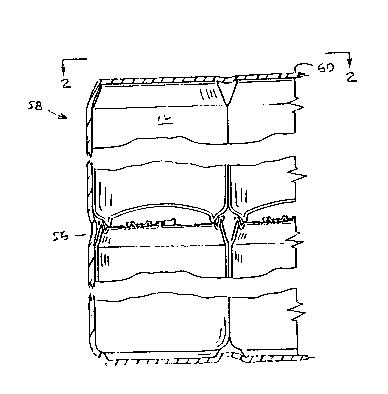
FIGURE 1 is a front elevation of beverage containers that are bundled by
shrink wrapping with plastic film;
FIGURE 2 is a top view of the bundled beverage containers of FIGURE 1
taken substantially as shown by view line 2-2 of FIGURE l;
FIGURE 3 is a cross sectional elevation of the lower portion of one of
the beverage containers of FIGURES l and 2, showing details that are generally
common to two prior art designs;
FIGURE 4 is a cross sectional elevation of the lower portion of a
:
beve,age container, showing details that are generally common to the preferred
ts of the present invention;
FIGURE 5 is a cross sectional elevation, showing, at an enlarged scale,
details that are generally common to both FIGURES 3 and 4:
- FIGURE 6 is a graph of cumulative drop heights vs. both the radius of
: lS curvature of the domed panel, and the ratio of the radius of curvature dividet
by the mean diameter of the annular supporting portion, with the distsnce from
the supporting surface to the domed panel being constant;
FIGURE 7 is a graph o f cumulative drop heights vs. both ehe radius of
curvature of the domed panel, and the ratio of the radius of curvature divided
by the mean diameter of the annular supporting portion, and is different from
the graph of FIGURE 6 in that parameters, such as the inner wall height have
been selected to provide a constant static dome reversal pressure;
- FIGURE 8 is a graph of static dome reversal pressures vs. both the radius
~:. of curvature, and the ratio of the radius of curvature dLvided by the mean
: 25 diameter of the annular supporting portion, with the dome height, that is, the
-: .:
~ :~ distance fro- the supporting surface to the domed panel, being constant; and
.~ .
: 12
,. ~ :,, .
., - .
~:
20388i7
-~ FIGURE 9 is a graph of static dome reversal pressure vs. both the radlus
of curvature of the domed panel, and the ratio of the radius of curvature
divided by the mean diameter of the annular supporting portion.
DescriDtion of the Preferred Embodiments
Referring now to FIGURES 3, 4, and 5, these configurations are generally
common to Pulciani et al. in U.S. Patents 4,68S,582 and 4,768,672 and
4,620,434, to a design manufactured by the assignee of the present invention,
and to embodiments of the present invention. More particularly, FIGURE 3 is
common to the aforesaid prior art, FIGURE 4 is common to two embodiments of
the prior art, and FIGURE 5 shows some details of FIGURES 3 and 4 in an
enlarged scale.
Since the present invention differs from the prior art primarLly by
selection of some of the parameters shown in FIGURES 3-5, the forthr. ~ne
description refers to all of these drawings, except as stated otherwise; and
some dimensions pertaining to FIGURES 3 and 4 are placed only on FIGURE 5 in
order to avoid crowding.
Continuing to refer to FIGURES 3-5, a drawn and ironed beverage container
10 includes a generally cylindrical sidewall 12 that includes a first diameter
D1, and that is disposed circumferentially around a vertical axis 14; and an
annular supporting portion, or annular supporting means, 16 that is disposed
circumferencially around the vertical axis 14, that is disposed radially
inwardly from the sidewall 12, and that provides an annular supporting surface
18 that coincides with a base line 19.
The annular supporting porcion 16 includes an outer convex annular
portion 20 that preferably is arcuate, and an inner convex annular portion 22
that preferably is arcuate, that is disposed radially inwardly from the outer
convex annular portion 20, and chat is connected to the outer convex annular
13
2038817
- portion 20. The outer and inner convex annular portions, 20 and 22, have
radii Rl and R2 whose centers of curvaeure are common. More particularly, ehe
radii R1 and R2 both have centers of curvature of a po$nt 24, and of a circle
of revolution 26 of the point 24. The circle of revolution 26 has a second
diameter D2.
An outer connecting portion, or outer connecting means, 28 includes an
.- upper convex annular portion 30 that is preferably arcuste, that includes a
--~ radius of R3, and that is connected to the sidewall 12. The outer connecting
portion 28 also includes a recessed annular portion 32 that is disposed
radially inwardly of a line 34, or a frustoconical surface of revolution 36,
that is tangent to the outer convex annular portion 20 and the upper convex
annular portion 30. Thus, the outer connecting means 28 connects the sidewall
12 to the outer convex annular portion 20.
A domed panel, or concave panel, 38 is preferably spherically-shaped, but
may be of any suitable curved shape, has a radius of curvature, or dome
radius, R~, is disposet radially inwardly from the annular supporting portion
16, and curves upwardly into the container 10. That is, the domed panel 38
curves upwardly proxLmal to the vertical axis 14 when the con~A~r 10 is in
an upright position.
- 20 The contaLner 10 further includes an inner connecting portion, or inner
connecting means, 40 having a circumferential inner wall, or cylindrical inner
wall, 42 with a height Ll that extends upwardly with respect to the vertical
axis 14 that may be cylindrical, or that may be frustoconical and slope
inwardl~ toward said vertical axis 14 at an angle 1. The inner connecting
portion 40 also includes an inner concave annular portion 44 that has a radius
Rs, and that interconnects the inner wall 42 and the domed panel 38. Thus,
2038817
the inner connecting portion 40 connects the domed panel 38 to the annular
supporting portion 16.
The inner connecting portion 40 positions a periphery 45 of the domed
panel 38 at a positional distance L2 above the base line 19. As can be seen
S by inspection of FIGURE 5, the positional distance L2 is approximately equalto, but is somewhat less than, the sum of the height L1 of the inner wall 42,
the radius of curvature RS of the inner concave annular portion 44, the radlus
R2 of the inner convex annular portion 22, ant the thickness of the material
at the inner convex annular portion 22.
`~ 10 As seen by inspection and as can be calculated by trigonometry, the
positional distance L2 is less than the aforementioned sum by a function of
the angle ~1, and as a function of an angle ~3 at which the periphery 45 of
the domed panel 38 is connected to the inner concave annular portion 44.
For example, if the radius R5 of the inner concave annular portion 44 is
15 0.050 inches, if the ratius R2 of the inner convex annular portion 22 is 0.040
inches, and if the thickness of the material at the inner convex annular
portion 22 is about 0.012 inches, then the positional distance L2 is about,
but somewhat less than, 0.102 inches more than the height Ll of the inner wall
42.
Thus, with radii and metal thickness as noted above, when the height L1
of the inner wall 42 is 0.060 inches, the positional distance L2 is about, but
a little less than, 0.162 inches.
The annular supporting portion 16 has an arithmetical mean diameter D3
that occurs at the ~unction of the outer convex annular portion 20 and the
inner co~vex annular portion 22. Thus, the mean diameter D3 and the diameter
2~38817
D2 of the circle 26 are the same diameter. The dome radius R4 is on the
vertical axis 14.
The recessed annular portion 32 includes a circumferential outer wall 46
that extends upwardly from the outer convex annular portion 20 and outwardly
away from said vertical axis by an angle o2, and includes a lower concave
annular portion 48 with a radius R6. Further, the recessed annular portion 32
may, according to the selected magnitudes of the angle ~2, the radius R3, and
the radius R6, include a lower part of the upper convex annular portion 30.
Finally, the container 10 includes a dome height, or panel height, Ht as
measured from the supporting surface 18 to the domed panel 38, and a post
diameter, or smaller diameter, D4, of the inner wall 42. The upper convex
annular portion 30 is tangent to the sidewall 12, and has a center 50. The
center 50 is at a height H2 above the supporting surface 18. A center 52 of
the lower concave annular portion 48 is on a diameter D5. The center 52 is
below the supporting surface 18. More specifically, the supporting surface 18
is at a distance H3 above the center 52.
Referring now to FIGURES 3 and 5, in the prior art embodiment of the
three aforesaid patents, the following dimensions were used: D1 - 2.597
inches; D2, D3 - 2.000 inches; D5 - 2.365 inches; Rl, R2 - 0.040 inches; R3 -
0.200 inches; R4 - 2.375 inches; R5 - 0.050 inches; R6 - 0.100 inches; and ~1 -
less than 5'. It should be noted that although R4 is 2.375 inches, the sctual
tooling radius therefor was 2.12 inches.
203881~
Referring again eO FIGURES 3 and 5, in the prior art embodiment of the
assignee to the present invention, the following dimensions were used: D1 -
2.598 inches; D2, D3 - 2.000 inches; D4 - 1.882 inches; D5 - 2,509 inches; R1,
R2 - 0.040 inches; R3 - 0.200 inches; R4 - 2.375 inches; R5 - 0.050 inches; R6
- 5 - 0.200 inches; H1 - 0.385 inches; H2 - 0.370 inches; H3 - 0.008 inches; ~1 -
5~ 9'; and ~2 - 30~. It should be noted that although R4 is 2.375 inches, the
actual tooling radius therefor was 2.12 inches.
Referring now to FIGURES 4 and 5, in tests run in conjunction with the
present invention, the following dimensions were used: D1 - 2.598 inches; D2,
D3 - 2.000 inches; D5 - 2.509 inches; R1, R2 - 0.040 inches; R3 - 0.200 inches;
Rs - 0.050 inches; R6 - 0.200 inches; H2 - 0.370 inches; H3 - 0.008 inches; ant
~2 - 30.
The other dimensions, such as R4, D4, H1, ~1, L1, and the thickness of
material which were uset in the tests, are as specifiet in the tables which
are includet herein, together with the test results thereof.
In each of the tables, the static tome reversal pressure (S.D.R.) is in
pounts per square inch, the cumulative trop height (C.D.H.) is in inches, and
the internal pressure (I.P.) at which the cumulative trop height test~ were
run is in pounds per square inch.
Referring now to Tables l-lO, the radius of curvature R4 of the domed
panel 38, as specifiet in the tables, is the actual ratius of curvature of the
~03~817
container, as measured, not the radius of curvature of the domer tooling. For
instance, a radius of curvature R4 of 2.375 inches, is made with a tool that
_ has a radius of 2.120 inches. This difference in radius of curvature for the
- actual container and the tooling is true for both the three aforementioned
patents and the prior art embodiments of ehe assignee of the sub~ect
in~ention.
More particularly, in Tables 1-10 the following Table A comparison
between toolin~ radius and the actual dome radius R4 of the containers.
Table A
Tooling Dimension Can Dimension
2.12 inches 2.375 inches
2.05 inches 2.288 inches
1.95 inches 2.163 inches
1.85 inches - 2.038 inches
1.75 inches 1.913 inches
1.65 inches 1.750 inches
~,.
, . ., . . _, . . ...
Therefore, in the tables, a radius of curvature R4 of 2.375 compares to the
prior art of FIGURES 3 and 4, in which the radius of the domer tooling was 2.120
inches; and the improvements of the present invention, at other radii of
curvature, can be seen as a comparison to an a4 of 2.375 inches.
The tests of Tables 1-10 were run with two thickness of metal, as
15 specified. The 0.0118 inch thickness is the standard gauge for use in the
United States; and the 0.0127 inch thickness is used for special orders,
particularly for use outside the Unitet States All of the test materlal was
aluminum alloy which is desi~nated as 3104 H19, and the test msterial was taken
from production stock.
.,
2~38817
The cumulative drop heights in the tables represent the average of eighteen
tests, and the static dome reversal pressures represent the average of ten
tests. The internal fluid pressures in each container prior to dropping is
shown in the table for each drop test.
The purpose for the cumulative drop height is to determine the cumulative
drop height at whLch a filled can exhibits partial or total reversal of the
domed panel.
The procedure is as follows: 1) warm the product in the containers to 90
degrees, plus or minus 2 degrees, Fahrenheit; 2) position the tube of the drop
10 height tester to 5 degrees from vertical to achieve consistent container drops;
3) insert the container from the top of the tube, lower it to the 3 inch
position, and support the container with a fLnger; 4) allow the container to
free-fall and strike the steel base; 4) repeat the test at heights that
successively increase by 3 inch increments; S) feel the domed panel to check for
lS any bulging or ~reversal~ of the domed panel before testing at the next height;
6) record the height at which dome reversal occurs; 7) calculate the cumulative
drop height, that i9, add each height at which a given container has been
dropped, including the height at which dome reversal occurs; and 8) average the
results from 10 containers.
One beverage producer has proposed that containers supplied to that company
have a minimum cumulative drop height resistance of 60 inches. Heretofore,
container manufacturers have been unable to achieve this cumulative drop height
resistance. Therefore, it is unknown whether an industry standard of 60 inches,
30 inches, or merely 20 inches, will be adopted. Further, it is not certain
25 that any industry standard will be adopted.
However, the present invention provides a container with a cumulative drop
- height resistance that greatly exceeds that of prior art containers; and
containers manufactured according to the present invention are able to meet a
2~3881~
cumulative drop heighe requirement of 20, 30, 40, or even 60 inches without any
increas- in the gauge of the material, and without any increase in coSe.
Table 1
- Metal
Thkns: 0.0118 0.0127 0.0118 0.0127
R4 2.375 2.375 2.375 2.375
D4 1. 8820 1.8820 1.8820 1.8820
Hl 0.3861 0.3832 0.3861 0.3832
3 2 3 2
Ll 0.110 0.090 0.110 0.090
S.D.R. 95.8 110.9 95.8 110.9
C.D.H. 5.0 17.5 5.0 17.5
I.P. 62.4 61.0 62.4 61.0
R4/D2 1.188 1.188 1.188 1.188
R4/D1 b . 914 0.914 0.914 0.914
Hl/D2 0.193 0.192 0.193 0.192
H1/D1 0.149 0.147 0.149 0.147
Ll/D2 0.05S 0.045 0.055 0.045
Ll/D1 0. 042 0.035 0.042 0.035
Table 2
Meeal
Thkns: 0.0118 0.0127 0.0118 0.0127
R4 2.288 2.288 2.288 2.288
D4 1. 8870 1.8870 1.8870 1.8870
H1 0. 3855 0.3864 0.3855 0.3864
~1 2 1.5 2 1.5
Ll 0.095 0.090 0.095 0.090
S.D.R. 95.9 113.1 95.9 113.1
C.D.H. 9.0 23.6 9.0 23.6
I.P. 63.6 60.0 63.6 60.0
R4/D2 1.144 1.144 1.144 1.144
R4/D1 0. 881 0.881 0.881 0.881
Hl/D2 0.193 0.193 0.193 0.193
Hl/D1 0.148 0.149 0.148 0.149
Ll/D2 0. 048 0.045 0.048 0.045
Ll/D1 0.037 0.035 0.037 0.035
,,
2~3~8~'~
Table 3
Metal
Thkns: 0.0118 0.0127 0.0118 0.0127
R4 2.288 2.288 2.288 2.288
D4 1. 8820 1.8820 1.8820 1.8820
Hl 0. 3851 0.3851 0.3928 0.3851
~1 2 2 1.5 2
Ll 0.080 0.085 0. O9S 0.085
S.D.R. 94.3 109.7 9S.S 109.7
C.D.H. 8.7 22.0 8.3 22.0
I.P. 63.2 62.2 64.7 62.2
R4/D2 l.144 1.144 1.144 1.144
R4/Dl 0. 881 0.881 0.881 0.881
Hl/D2 0.193 0.193 0.196 0.193
Hl/Dl 0.148 0.148 0.151 0.148
Ll/D2 O. 040 0.043 0.048 0.043
Ll/Dl 0. 031 0.033 0.037 0.033
Table 4
Metal
Thkns: 0.0118 0.0127 0.0118 0.0127
R4 2.163 2.163 2.163 2.163
D4 1. 8870 1.8870 1.8810 1.8870
H1 0.3863 0.3856 0.4021 0.3971
~1 1.5 1 1.5 1.5
Ll 0.075 0.075 0.085 0.090
S.D.R. 92.9 106.0 96.9 111.7
C.D.H. 18.0 37.7 ` 13.5 37.7
I.P. 62.6 62.5 64.8 62.8
R4/D2 1.081 1.081 1.081 1.081
R4/Dl 0. 833 0.833 0.833 0.833
Hl/D2 0.193 0.193 0.201 0.199
Hl/Dl O.149 0.148 0.155 0.153
Ll/D2 O. 038 0.038 0.043 0.045
Ll/D1 0.029 0.029 0.033 0.035
2~38817
" "
.
Table 5
, .
Metal
Thkns: 0.0118 0.0127 0.0118 0.0127
R4 2.163 2.163 2.163 2.163
D4 1.8820 1.8820 1.8820 1.8820
Hl 0.3839 0.3839 0.4101 0.4057
~t 2 2.75 2.5 1.25
Ll 0.060 0.070 0.100 0.090
S.D.R. 89.2 104.7 97.6 112.7
C.D.H. 17.5 36.7 16.5 29.8
I.P. 63.0 61.2 63.3 63.3
R4/D2 1.081 1.081 1.081 1.081
R4/D1 0.833 0.833 0.833 0.833
Hl/D2 0.192 0.192 0.205 0.203
Hl/Dl 0.148 0.148 0.158 0.156
L1/D2 0.030 0.035 0.050 0.045
Ll/Dl 0.023 0.027 0.038 0.035
.
,
,.. ,_, _ _, . .. ... .
Table 6
Metal
Thkns: 0.0118 0.0127 0.0118 0.0127
R4 2.038 2.038 2.038 2.038
D4 1.8870 1.8870 1.8870 1.8870
Hl 0.3863 0.3851 0.4178 0.4137
~1 1.5 1 1 1.5
Ll 0.055 0.055 0.090 0.090
S.D.R. 87.9 102.4 97.2 112.8
C.D.H. 31.7 65.5 26.0 57.0
I.P. 63.0 60.3 62.5 61.3
R4/D2 1.019 1.019 1.019 1.019
R4/D1 0.784 0.784 0.784 0.784
Hl/D2 0.193 0.193 0.209 0.207
H1/D1 0.149 0.148 0.161 0.159
L1/D2 0.028 0.028 0.045 0.045
L1/D1 0.021 0.021 0.035 0.035
- 2~38817
"~ Table 7
Me tal
Thkns: 0.0118 0.0127 0.0118 0.0127
R4 2. 038 2.038 2.038 2.038
D4 1. 8820 1.8820 1.8820 1.8820
Hl 0.3855 0.3865 0.4246 0.4222
4.5 2 2.S 1.5
Ll 0. 065 0.060 0. lO0 0.105
S.D.R. 86.1 101.8 98.4 113.4
C.D.H. 40.0 59.0 - 25.9 53.0
I.P. 60.5 63.2 62.4 64.2
R4/D2 1.019 1.019 l. 019 1.019
R4/Dl 0. 784 0.784 0.784 0.784
Hl/D2 0.193 0.193 0.212 0.211
Hl/Dl O.148 0.149 0.163 0.163
Ll/D2 O. 033 0.030 0.050 0.053
Lt/Dl 0. 025 0.023 0.038 0.040
Table 8
Me tal
Thkns: 0.0118 0.0127 0.0118 0.0127
R4 1. 913 1.913 1.913 1.913
D4 1. 8870 1.8870 1.8870 1.8870
H1 0.3868 0.3852 0.4250 0.4216
Q1 3 2.5 1.5 2
L1 O. 050 0.045 0.085 0.090
S.D.R. 85.5 101.7 96.0 111.0
C.D.H. 59.7 112.2 44.2 89.1
I.P. 60.663.5 61.3 60.0
R4/D2 O. 956 0.956 0.956 0.956
R4/D1 O. 736 0.736 0.736 0.736
H1/D2 0.193 0.193 0.213 0.211
H1/D1 0.149 0.148 0.164 0.162
L1/D2 0.025 0.023 0.043 0.045
L1/D1 0.019 0.017 0.033 0.035
23
2~388~ ~
Tsble 9
Metal
Thkns: 0.0118 0.0127 0.0118 0.0127
R4 1. 913 1.913 1.913 1.913
D4 1. 8820 1.8820 1.8820 1.8820
Hl 0.3868 0.3843 0.4273 0.4265
~ S 5 3.5 2.5
Lt 0.045 0.045 0.085 0.090
S.D.R. 84.3 99.5 93.2 108.9
C.D.H. 54.5 114.7 51.0 92.0
I.P. 62.7 60.2 61.2 63.3
R4/D2 O. 956 0.956 0.956 0.956
R4/Dl 0. 736 0.736 0.736 0.736
H1/D2 0.193 0.192 0.214 0.213
Ht/Dl 0.149 0.148 0.164 0.164
Ll/D2 O. 023 0.023 0.043 0.045
Ll/Dl 0.017 0.017 0.033 0.035
Table 10
Metal
Thkns 0.0118 0.0127 0.0118 0.012?
R4 1. 750 1.750 1.750 1.750
D4 1. 8870 1.8870 1.8870 1.8870
Hl 0.3850 0.3850 0.4289 0.4275
~1 4 5 2.5 2
Ll 0.035 0.035 0.080 0.075
S.D.R. 83.3 98.6 91.4 106.9
C.D.H. 73.5 137.7 70.0 136.0
I.P. 63.6 60.4 64.8 62.7
R4/D2 O. 875 0.875 0.875 0.875
R4/Dl 0. 674 0.674 0.674 0.674
Hl/D2 0.193 0.193 0.214 0.214
Hl/D1 0.148 0.148 0.165 0.165
Ll/D2 O. 018 0.018 0.040 0.038
Ll/Dl 0.013 0.013 0.031 0.029
203~7
Table 11
Constant Dome Depth
Test R4 D4 R4/D2 SDR SDR CDH CDH
.0118 .0127 .0118 .0127
B6A 2.375 1.882 1.18895.8110.9 5.0 17.5
X0133 2.288 1.887 1.14495.9 113.1 9.0 23.6
X0132 2.288 1.882 1.14494.3 109.7 8.7 22.0
X0131 2.163 1.887 1.08192.9 106.0 18.0 3t.7
X0130 2.163 1.882 1.08189.2 104.7 17.5 36.7
X0129 2.038 1.887 1.01987.9 102.4 31.7 65.5
X0123 2.038 1.882 1.01986.1 101.8 40.0 59.0
X0128 1.913 1.887 0.95685.5 101.7 59.7 112.2
X0113 1.913 1.882 0.95684.3 99.5 54.5 114.7
X0135 1.7S0 1.887 0.87583.3 98.6 73.5 137.7
Table 12
Constant SDR
Test R4 D4 R4/DZ Hl H1 CDH CDH
.0118 .0127 .0118 .0127
B6A 2.375 1.882 1.188 .386 .383 5.0 17.5
X0133 2.288 1.887 1.144 .386 .386 9.0 23.6
X0132 2.288 1.882 1.144 .393 .385 8.3 22.0
X0131 2.163 1.887 1.081 .402 .397 13.5 37.7
X0130 2.163 1.882 1.081 .410 .406 16.5 29.8
X0129 2.038 1.887 1.019 .418 .414 26.0 57.0
X0123 2.038 1.882 1.019 .425 .422 25.9 53.0
X0128 1.913 1.887 0.956 .425 .422 44.2 89.1
- X0113 1.913 1.882 0.956 .427 .427 51.0 92.0
X0135 1.750 1.887 0.875 .429 .428 70.0 136.0
- 2~38817
.,
Referring now to Table 1, it will be noticed that the numbers in columns
three and four correspond exacely to the numbers in columns one and two. The
reason for this is thae the object in the tests for columns three and four was
to vary the dome depths to match the static dome reversal of the prior art of
FIGURE 4. Since the parameters of Table 1 are the same as that of the prLor
art of FIGURE 4, the numbers in columns three and four are identical to those
in columns one and two.
Continuing to refer to Table 1, and test results for the prior art
configuratLon of FIGURE 4, the cumulative drop heights were 5.0 inches and
17.5 inches, for metal thicknesses of 0.0118 inches and 0.0127 inches,
respectively, and with internal pressures of 62.4 pounds per square inch and
61.0 pounds per square inch, respectively. Notice that the static dome
reversal pressures were 95.8 and 110.9 pounds per square inch for the two
metal thicknesses.
It i important to remember that the radius of curvature of the domed
panel for Table 1, as listed~ is 2.375 inches, and that this is the actual
radius of curvature for prior art in which the domer eooling radius is 2.120
inches.
,,-- Referring now to Table 10, in stark contrast to test results on the prior
art embodiment of Table 1, with a dome radius R4 of 1.750 inches of the
container, and with a post diameter D4 of 1.887 inches for the same two metal
thicknesses, 0.118 inches and .0127 inches, and for internal pressures of 63.6
psi and 60.4 psi, respectively, the cumulative drop heights of the present
invention were 73.5 inches and 137.7 inches, respectively, as shown in columns
one and ewo. Noeice that the static dome reversal pressures were 83.3 psi and
98.6 psi, respectively.
26
:
203~81~
That is, the present invention increased the cumulative drop height by
more than fourteen times, from 5.0 inches to 73.5 inches for the thlnner
stock, and by nearly eight times, from 17.5 inches to 137.7 inches for the
thicker stock.
However, referring to Tables 1 and 10, this dramatic increase in the
cumulative drop height was accompanied by an undesirably large decrease in the
static dome reversal pressures. The dome reversal pressures reduced from 95.8
psi and 110.9 psi, respectively, for the thinner and the thicker stock in
Table 1, to 83.3 psi and 98.6 psi, respectively, for the thinner and the
thicker stock of Table 10.
The present invention provides means for obviating, or at least
ameliorating, thls decrease in the static dome reversal pressure that
accompanies the dramatic increase in the cumulative drop height.
Referring now to Table 1 and to columns three and four of Table 10, the
present invention increased the cumulative drop height from S.0 inches and
17 5 inches, respectively, to 70.0 inches and 136.0 inches, respectively for
the thinner and the thicker stock. Therefore, the present invention increased
the cumulative drop height by fourteen times for the thinner stock and by
almost eight times for the thicker stock.
20 At the same time, by increasing the height L1 of the inner wall 42, from
- 0.035 inches to 0.080 inches for the thinner stock and 0.075 inches for the
thicker stock, the containers had a static dome reversal pressure of 91.4 psi
and 106.9 psi respectively.
Therefore, increasing the height L1 of the inner wall 42 limited the
reduction in the static dome reversal pressure to less than 5 percent for the
thinner stock, and by 4 percent for the thicker stock, while achievi~g
. ~ increases in the cumulative drop height by about eight to fourteen times,
~ depending upon the meeal thlckness.
: ~
2~338~7
Referring now to FIGURE 9, cumulative drop heights and static dome
reversal pressures are shown for various radii of curvature R4 of the domed
panel 38, and for various ratios of radii of curvature R4 to the mean diameter
D3 of the annular supporting portion 16.
- 5 Notice that in FIGURE 9, with increased heights Ll of the inner wall 42,
it is possible to obtain phenomenal, but not maximum, increases in the
cumulative drop heights without decreasing the staeic dome reversal pressure
below that which was achieved by the prior art.
Or, referring now to Tables 1 and 8, notice that the prior art static
dome reversal pressures of 9S.8 and 110.9 of Table 1, are eYcee~d by the
static dome reversal pressures of 96.0 and 111.0 of Table 1, and thae
increases in cumulative drop heights from 5.0 inches to 44.2 inches, and from
17.5 inches to 89.1 inches, respectively, are achieved.
Therefore, in the present invention, highly significsnt increases in the
cumulative drop heights can be achieved without any reduction in static dome
reversal pressures.
Furthermore, it is believed that further ~ ro~ t is possible by
varying such parameters as the angle ~1 of the inner wall 42, and the height
Lt of the inner wall; because the test results submitted herein indicate ehat
increasing ehe height Ll increases the static dome reversal pressure, and
decreasing the angle Ql of ehe inner wall 42 increases ehe static dome
reversal pressures.
Referring now to FIGURE 6 and Table 11, the test data of Tables 1-10 has
been rearranged in Table 11 to show variations in test results when the dome
height Hl is kept constant; and in FIGURE 6, the data of Table 11 is plotted
to show the cumulative drop heights vs. the radius of curvature R4 for tests
28
~3~817
wherein the dome height Hl is kept constant at 0.385 inches.
It should be noted ehat in Tables 11 and 12, the designation ~6A denotes
a container made in accordance with the dimensions presently given for the
prior art container of the assignee of the sub~ect invention. the other
container designations te.g., X0133~ refer to experimental drawing numbers of
various experimental tools.
In like manner, referring now to FIGURE 7 and Table 12, the test data of
Tables 1-lO has been rearranged in Table 12 to show variations in test results
when the dome height H1 is varied to maintain a constant, or nearly constant,
static dome reversal pressure of 96 psi for the 0.0118 inches stock thickness
and 111 psi for the 0.0127 inches stock thickness. In FIGURE 7, the data of
Table 12 is plotted to show the cumulative drop heights vs. the radius of
curvature R4 for tests whereLn the static dome reversal pressure is kept
constant, or nearly constant, as noted for Table 12.
Referring now to FIGURE 8, the static dome reversal pressures are plotted
for various radii of curvature R4 of the domed panel 38, and for various
ratios of radii of curvature R~ to the mean diameter D~ of the annular
supporting portion 16. In the curves of FIGURE 8, the dome height Hl, that
is, the distance from the supporting surface 18 to the domed panel 38 along
the axis 14, is kept constant at 0.385 inches.
In summary, the present invention yields unexpected results. It is
believed that one skilled in the art would not have anticipated that a
decrease in the dome radius R4 would achieve such a remarkable increase in
cumulative drop strengths. Moreover, it is believed that there is no hint in
the prior art that any increase in cumulative drop strength can be achieved by
~38~'7
a reduceion in the dome radius R4 as disclosed and claimed herein.
In addition, being able to reduce, or to obviate, the reduction in static
dome reversal pressures that accompanies this pher.---r-l increase in
cumulative drop heights, or even being able to increase the static dome
reversal pressure, by lncreasing the height Ll of the inner wall 42
constitutes unexpected results.
-- In order to better understand the claims, it should be recognized tha~
~. .. _ ,
increasing the height Ll of the inner wall 42, for a given radius of curvature
R4 of the domed panel 38, increases the dome height Hl.
Therefore, reciting an increase in the dome height Hl, or a limit
thereof, is one way of reciting an increase in, or a limit of, the height Ll
of the inner wall 42.
Further, it should be recognized that increasing the height Ll of the
inner wall 42 increases the positional distance L2.
Therefore, reciting an increase in the positional distance L2, or a limit
thereof, is one way of reciting an increase in, or a limit of, the height Ll
of the inner wall 42.
Further, it should be understood that reciting the positional distance L2
-~ distinctly defines dimensions, or limits, of the present invention without
regard to the size or shape of the inner convex annular portion 22, the size
or shape of the inner concave annular portion 44, the shape or inclination of
the inner wall 42, or the thickness of the metal.
Finally, the present invention provides these remarkable and unexpected
improvements by means and method as recited in the aspects of the invention
which are included herein.
`"`.~ 2~8gi7
Alehough aluminum containers have been investigated, it is believed that
the same principles, namely decreasing the dome radius R4, increasing the
height Ll o,f the inner wall 42, increasing the dome height Hl, increasing the
positional distance L2 from the supporting surface 18 to the domed panel 38,
and selecting, and/or minimizing the angle Ql of the inner wall 42, would be
effective to increase the strength of containers made from other materials,
including ferrous and nonferrous metals, plastic and other nonmetallic
materials.
Referring finally to FIGURES 1 and 2, upper ones of the containers 10
stack onto lower ones of the containers 10 with the outer connecting portions
28 of the upper ones of the containers 10 nested inside double-seamed tops 56
of lower ones of the containers 10; and both ad~acently disposed and
vertically stacked containers 10 are bundled into a package 58 by the use of a
shrink-wrap plastic 60.
While this method of p~ee~ne is more economical than the previous
method of boxing, possible damage due to rough handling becomes a probleo, so
that the requirements for cumulative drop resistances of the containers 10 is
more stringent. It is this problem that the present invention addresses and
solves.
While specific methods and apparatus have been disclosed in the preceding
description, it should be understood that these specifics have been given for
the purpose of disclosing the principles of the present invention and that
many variations thereof will become apparent to those who are versed in the
art. Therefore, the scope of the present invention is to be determined by the
- 25 appended claims.
2n3~sl7
Industrial ADplicability
- The present invention is applicable to containers made of aluminu~ and
various other materials. ~ore particularly, the present invention is
applicable,to beverage containers of the type having a seamless, drawn and
ironed, cylindrically-shaped body, and an integral bottom with an annular
supporting portion.