Note: Descriptions are shown in the official language in which they were submitted.
- 1- 2~ 2~
LENS GRINDING METHOD AND APPARATUS
The present invention relates to a method and
apparatus for generating ophthalmic lenses, in particular
spherical and sphero-cylindrical lenses, and more
particularly to the generation of ophthalmic lenses with
base curves providing optical powers in the range from
zero dioptres to at least twenty dioptres.
The traditional technique for making ophthalmic
lenses inYolves repeated grinding passes usually known as
sweeps across a lens blank with a cutting tool, which is
usually a circular cup shaped diamond tool. The sweeps
are continued until the blank has been shaped to the
desired surface curvature and lens centre thickness. The
optical powers of the range of curvatures produced by
available conventional lens grinding machines in the
spherical meridian is in the range from 3 to 20 dioptres.
It is desirable to extend that range down to zero dioptres
i.e. lenses with no curvature in the spherical meridian.
The extension of the range of lens grinding machines has
been the subject of previous proposals. For e~ample,
US-A-4 535 566 describes a mechanical system in which the
locus of _ _ _ _
the grinding wneel can be varied to extend the range of the
system. The basis oY this proposal is to use a cam follower
mechanism to radially reposition the diamond tool as it is
swept over the lens blank surface. The change in the sweep
radius length while sweeping simulates a particular radius of
curvature. The operations described in US-A-4 535 566
require a designated cam surface (or template) for every
specific base curve it is desired to generate. US-A-4 535 566
maintains the same head angle. i.e. the angle at which the
tool head is set to a tangent to the curve being cut
throughout the sweep by means of a complex four bar linkage
which must be adjusted according to the dasired Rrescription
before the lens generation process begins. Thus this prior
proposal provides a lens grinding machine which while having
an extended range, is only adjustable to produce selected
curves within that range, and requires a skilled operator to
set the machine up for a particular power.
An aim of the present in~ention is to produce a lens
grinding machine and a lens generating method which can be
operated with limited operator attention and the use of
relatively unskilled operators in that no complex setting up
procedures are required by utilising numerical control
procedures. It is a further aim to produce a machine with
an extended range, which can be produced by relatively modest
machine modi~ications to existing designs.
-- 3
The present invention provides a method of
generating a lens having desired base and cross curvatures
by means of a circular cup shaped diamond tool, which is
rotated about an axis and is swept repeatedly over a lens
blank to remove material so as to generate the re~uired
surface, the tool being positioned so as to produce the
desired combination of base and cross curvatures on the
blank, the method comprising positioning the diamond tool
by means of a cross slide and a base slide, both of which
slides are free to move during the generation of the
surface; sweeping the rotating tool over the lens blank
and adjusting the cross slide and/or the base slide during
the sweep thereby to vary the head angle of the tool
during the sweep such that at any position in the sweep
lS the instantaneous head angle is at a value whereby the
desired cross curvature produced is constant over the
sweep.
The present invention also provides a lens
generating machine comprising a base, a tool supporting
mechanism and a lens supporting mechanism, both of the
mechanisms being mounted on the base, the tool supporting
mechanism comprising a diamond tool, a base slide and a
cross slide on which the tool is mounted and means for
rotating the tool, the tool supporting mechanism being
adapted to sweep the tool over the lens blank to generate
a lens.having desired base and cross curvatures, and means
for adjusting the cross slide and/or the base slide during
a sweep thereby to vary a head angle of the tool during
the sweep such that at any position in the sweep the
instantaneous head angle is at a value whereby the desired
cross curvature produced is constant over the sweep.
In the operation of a conventional lens grinding
maclline, the head angle is fixed during the sweep by
clamping the cross slide. The head angle has previously
been selected and the adjustment of the cross slide
already made prior to
4 2~2$~
clamping. The base slide is then positioned so that th0 tool
edge is the radius of the prescription base curve away from
the axis about which the tool is swept. The lens blank is
then movedto~rds the tool so that the finished lens will
have a pre-determined lens thickness when the sweeping action
is completed. Lens and tool are stepped toward each other as
the sweeping action progresses so that a constant amount of
material is removed at each sweep.
In the method of the present invention, an additional
degree of motion is provided which enables an extended range
of curves to be generated. This is achieved by clamping
neither the cross slide nor the base slide in a fixed
position during the shaping of the lens blank. The cross
slide is simply positioned at an initial head angle, and the
lS base slide at an initial distance from the sweep axis. The
base slide position when operating the machine in the range
feasible in the prior art mode is fixed at a distance away
from the sweep pivotal axis equal to the base curve radius.
-Operating in the range 0-3 dioptres, the base slide i9
positioned at a known reference radius(which is measured at the
centre of the lens) from the sweep pivotal axis, e.g. 170 m~
and this reference radius can be extended or retracted by a
particular amount when the base slide is moved away from~ or towards
the lens centre so as to produce the desired base curve. In
the case of a 170 mm reference radius, the base slide
position can change 6 mm up to 176 mm for an 80 mm diameter
lens.
~5-
As regards the position of the cross slide, if this is
positioned so that the diamond tool is at the lens centre,
the tool will be at the desired base radius from the sweep
pivotal axis, and the real head angle of the diamond tool is
at the angle required to generate the desired cross curve,
and the sweep angle will be zero.
As the tool moves away from the lens centre, and the
sweep angle increases, in order to maintain the tool in the
correct generating position, the base slide must extend out
to enable the tool to move along the path of the desired base
curve. The head angle of the diamond tool must be adjusted
so that at any particular point on the sweep it is at a
const ~ ~ qual to the head angle when the sweep angle
was at zero. This results in the tool angle being effectively
the angle which results in the required cross curve being
generated.
In order to carry out the above operations, it is
therefore necessary to constantly sample the sweep angle
during the sweep and adjust the base and cross slide
positions in relation to the position of the tool in its
sweep so as to maintain the tool at the desired effective
head angle to generate the required cross curve, and the
desired distance from the sweep pivotal axis to produce the
required base curve. The machine must therefore be provided
with means to determine the sweep angle, and the base slide
must be mounted so as to be able to be positioned at a
constantly changing distance from the pivotal sweep axis.
2 ~
-- 6
An embodiment of the present invention will now be
described by way of example only with reference to the
accompanying drawings, in which:-
Figure 1 is an elevation of a known form of lens5 qenerating machine;
Figure 2(a) is a diagrammatic top view of a lens
generating machine according to the invention;
Figure 2(b) is a diagrammatic front view of a lens
generating machine according to t.he invention;
Figure 3(a) is a diagrammatic view of how the
desired cross curve is cut by the diamond tool of the
machine of Figure 2;
Figure 3(b) is a diagrammatic view showing the
path followed by the diamond tool of the machine of Figure
2 to generate the desired base curve;
Figure 4 is a diagrammatic view of the
relationship, in the operation of th ~ f Figure 2,
between the corrected head angle ~ whl ~ hept constant
throughout the sweep,~ o the head angle to produce a
reference base radius curve,~ ' the adjustment to~o to
achieve a setting at the head angle~ , and ~ '' the head
angle made with the desired curve; and
Figure 5 is a flow chart showing the operations
performed by the machine of Figure 2 during each sweep in
order to maintain the head angle necessary to generate the
desired cross curve, and the base slide position to
achieve the desired base curve.
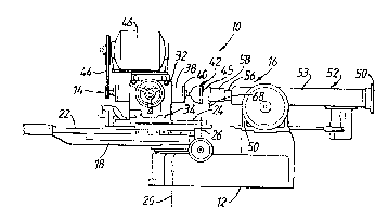
Referring first to Figure 1, a known lens curve
generating machine 10 comprises a base 12 on which are
mounted a tool supporting mechanism 14 and a lens
supporting mechanism 16.
~7- ~ ?J~ ~
The tool supporting mechanism is similar to that described in
US-A-2 806 327 and US-A-3 289 355, the disclosures oF which
are incorporated by reference herein. Basically, the tool
supporting mechanism 14 comprises a plate 18 which is
pivotably mounted to the base 12 for rotation about a
vertical axis 20. Slidably mounted on a horizontal surface
of the plate 18 is a tool support comprising a base curve
slide 22, and a cross curve slide 24 pivotably mounted to the
base curve slide for rotation about a vertical axis 26 defined
by a pin (not shown). The base curve slide 22 can be adjusted
horizontally relative to the plate 18 in a fore-to-aft
direction toward and away from the lens supporting mechanism.
The cross curve slide 24 can be adjusted relative to the base
curve slide 22 about the axis 26.
Mounted on the cross curve slide 24 is a bearing block
32 which is adapted to slide hori~ontally relative to the
cross curve slide 24 in a direction perpendicular to the
fore to-aft direction. This is achieved by mounting the
bearing block 32 by means of a dove-tail track 34 and
providing a conventional adjustment means.
A spindle housing 38 mounted in the bearing block 32
rotatably carries a shaft 40 on one end of which a diamond grinding
tool 42 is supported. The opposite end of the sha~t is
driven by a belt drive 44 from a motor 46 resting atop the
bearing block 32.
The tool 42 is cup-shaped and presents a curved cutting
edge 45. The curved edge 45 is rounded as vie~ed in
'2 ~
-8-
cross-section so as to define a centre of curvature spaced
from the plane of the curved edge. The arrangement of the
bearing block and spindle housing is such that the vertical
axis 26 is intersected by that centre of curvature during
each grinding sweep of the tool. The axis 26 thus defines a
tool reference axis. The grinding sweep of the tool is
effected by oscillating the tool supporting mechanism 14
about the vertical axis 20 after the tool 42 has been
properly positioned through appropriate adjustments o~ the base
curve slid~ 22, the cross curve slide 24 and the bearing block ~2.
The lens supporting mechanism 16 comprises a support
block 50 on which a tailstock assembly 52 is slidably
supported. The tailstock 52 includes a housing 53 which can
be reciprocated in a horizontal fore-to-aft direction by
conventional means. A shaft 56 is mounted in the tailstock
for reciprocable movement relative to the housing 53 in the
fore-to-aft direction. A front end of the shaft 56 carries a
lens holder in the form of a conventional chuck 58. The
chuck includes a space ring with a lens blank inserted so
that a so-called "front curve" of the lens abuts against a
front surface of the space ring. That surface defines a
vertical lens reference plane 68 disposPd perpendicular to
the fore-to-aft direction of movement of the shaft 56 and
parallel to the tool reference axis 26.
The operation of this machine to generate a particular
base and cross curve will now be described. The cross slide
24 is moved to a position at which the head of the diamond
9 2~2~
tool will be at the head angle necessary to generate the
desired cross curve. The cross slide 24 is then clamped in
that position. The base slide 22 is then moved to a position
such that the tool edge is the radius of the desired
prescription curve away from the sweep axis, and the base
slide is then clamped in position. The tailstock assembly 52
carrying the lens blank on which the curves are to be
generated is then moved to a position such that the lens
blank will be reduced to the desired lens centre thic~ness
once the curve generation has been completed. The tailstoc~
slide is then clamped in position and first sweep is
commenced. Between each sweep, the relative axial positions
of the lens and diamond tool are adjusted so that the diamond
tool contacts the blank to remove a further layer of the
surface on each sweep until the desired lens thickness is
achieved. The lens may then be removed for the further
operations necessary to convert it into its final form for
filling in frames which comprises at least fining, polishing,
and edging, but can also include tinting and coating with
such coatings as abrasion-resistant and anti-reflection
coatings.
Referring now to figures 2 and 3, in the lens
generating machine of the present invention, in order to enable the
machine to not only generate lenses having curves corresponding to
optical power ranging from 3 to 20 dioptres but additionally lenses
with curves corresponding to optical power ranging from ~ero
dioptres up to 3 dioptres, two features are
-10- 2~VlV~2~
required in addition to those conventionally available on a lens
grinding machine designed to produce lenses with curves corresponding to
optical power in the range 3 to 20 dioptres. The hydraulic cylinder
which positions the cross slide must be able to accommodate the
increased travel required to enable the additional range o~
powers to be achieved, and the slide bearing surfaces need to be
extended to accommodate the additional travel of the
cylinder. Existing machines are available whose design can
be simply modified, e.g. the machine sold by Coburn Optical
Inc. under the trade name "Coburn Model 2112 generator". The
amount of change and additional equipment required depends on
the sophistication of the original design, e.g. a hand
operated machine would require not only the slide bearing
surfaces to be modified but also the addition of powered
; 15 motion with their associated servo-mechanisms, encoders, and
- motion control cards with their associated micro-processor
equipment. It is essential that an encoder is present on the
sweep mechanism to allow the sweep angle to be measured, i.e.
- the angle that the base slide makes with the machine centre
2~ line.The latter is the line joining the point about which the
base line is pivoted ~the sweep pivot~ and the lens centre.
This measurement is then used as shown in the flow chart Fig
5 as input to the micro-processor so that the necessary
adjustments to be made to the cross-slide, and if necessary to the
base slide, can be ca1culated to ~aintain the head angle at the
value to give an effective head angle at which the required
cross curve will be produced.
2~ t~23~9
The conversion of the signal received Prom the encoder
to a signal to control the mechanical adjustment o~ the
position of both the base slide and the cross slide, and the
use of that signal is carried out in a manner well known to
those skilled in the art of servo controlled motion
mechanisms.
The parts shown in the diagramnatic view in figure 2
are those whose motion is controlled during the operation of
the machine. The machine has a base 71 on which there is
mounted a sweep platform 72, on which in turn there is
mounted a base slide 73, on which the cross slide 74 carrying
a diamond tool 75 driven by a motor 76 is mounted. A lens
blank supporting mechanism 77 is mounted on the base 71 and
the position of the lens blank 80 can be adjusted along an
axis A-A in relation to the diamond tool 75. Axis B-B is the
sweep axis about which the sweep platform 72 pivots when
driven by a hydraulic cylinder (not shown) so that the pivot
point 78 is at a distance equal to a desired base curve
radius from the sweep axis B-B. The cross slide 74 can be
pivoted about the pivot point 78 through which a vertical
line C-G passes and which line also passes along the cutting
edge 79 of the diamond tool. The diamond tool is then at a
head angle to the curve being cut. The head of the diamond
tool is of a circular cup shape so that at any head angle
other than zero, the result is that the circle is effectively
projected as an ellipse when considered in front view. It is
a portion of this ellipse which grinds through the lens
- 12 -
blank. Figure 3 shows how the ellipse approximates to a
circle of the desired radius with a so-called elliptical
error occurring at the edges. In Figure 3a, line 100
represents the desired cross curve, line 102 represents an
ellipse which approximates to the circle represented by
line 104 but leaves an elliptical error 106. The lens
blank 80 is moved along with its supporting mechanism 77
to a position such that at the end of the necessary number
of sweeps across the lens surface, the lens has a chosen
lens thickness as well as the desired surface shape.
Figure 3(b) shows the base slide 73 positioned on
the sweep platform 72 at the start position of the sweep.
The angle of the axis of these two components which passes
through the sweep axis and the pivot point 78 with the
axis passing through the lens centre being the sweep
angle. The sweep about the sweep axis is from this start
position to the reciprocal position on the other side of
the axis A-A.
Figure 4 shows the relationship between the
unadjusted head angle at location A, and the adjusted head
angle at location B which is achieved with a specific
cross slide movement for a particular point in the sweep,
i.e. the real time value of the sweep angle ~. The sweep
angle ~ is, in the Figure, a value of 48. Line 108
represents the reference radius of 170.0mm and line 110
represents the desired base curve. Line 11~ is the
direction leading to the desired centre of curvature.
In order to manufacture a lens with a base curve
having an optical powar of less than 3 dioptrres, the
diamond tool is moved to its initial position at say a
sweep angle of 48. The base slide is set so that the
radius of the swwp would be 170 mm. The cross slide is
then moved to a position such that the head angle of the
tool is equal to a value calculated using the reference
radius of 170 mm and a sweep angle of zero degrees. This
value is a constant for any desired base curve. The
-13- ~ ~ 3 ~
diamond tool is then in the position shown as A. In order to
put the diamond tool in the correct position for generating
.;
the desired base curve as shown, the base slide must be
extended to position B, and the diamond tool rotated by a
head angle adjustment ~' so that the angle ~" is equal to
; the above constant for the desired base curve. Then:
o = ~
is then the corrected head angle.
As the sweep angle decreases, the base slide will
retract until it reaches the lens centre, after which it will
extend. The head angle adjustment required to maintain the eff~rtive
- head angle constant will diminish to zero as the lens centre
- is reached, as at that point no correction to ~o is needed.
` Af~er the lens centre, the base slide extends, and the head
angle adjustment increases.
Referring ~o the flow chart figure 5, the iterative
sequence of operations will now be described in more detail.
During the sweep across the lens blank from the start
position to the end of the sweep, the angle of sweep i.e. the
- 20 angle to which the sweep platform 71 is pivoted, is sensed by
s means of a rotary encoder. The signal from the encoder is
processed and the adjustment of the cross slide needed to
maintain the head angle at the constant value determined.
The base s].ide radius is then determined, and the signal
processed so that the base slide may be positioned so as to
- 14 - 2~ 2~3~
maintain the sweep along the desired base curve. The process
is then repeated until the sweep is complete, and when the
sweep is complete, the distance between the lens blank and
the tool path is reduced by a pre-determined amount and the
next sweep commenced to remove further material and reduce
lens thickness. The micro-processor used for these
determinations, and the necessary electro-mechanical
equipment to carry out the necessary adjustments are both
conventional.
This method of operating a lens generating machine
enables the range of the machine to be extended below 3
dioptres. The machine can of course be operated in the range
from 3 to 20 dioptres and when operating in that range, the
base slide position does not alter during the generation of
the lens curvature.